
Installation Guide


INSTALLATION PROCEDURE — LARGE COVER
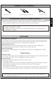
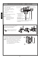
NOTE:
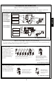
Base frame
Adjustable
plate
1. Determine the installation location of
the studs and water supply pipe
relative to the position of the
toilet/urinal.
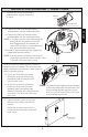
3. Attach the control stop to the pipe.
4. Bore a guide hole for the flush pipe
into the wall.
Attach the control stop
NOTE:
For reclaimed water, do not use
standard vacuum breaker or
control stop.
NOTE:
Do not use petroleum based products
or pipe sealants.
before installing the box
fixing frame. Thread sealing
compounds should only be
used on the male NPT
threads only.
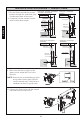
5. Fasten the base frame to the studs with
four screws (prepared on site) after
adjusting it. ( A )
6. Secure the box with four screws in the
adjustable plate. ( B )
For use with a left water supply,
detach the controller and remount it
to opposite side of valve body.
Detatch Remount
Valve body
7
ENGLISH
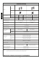
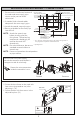
Adjustable holeAdjustable hole
Left water supply
1” NPT (toilet), 3/4” (urinal)
4-3/4” ± 1/2”
(120 ± 13mm)
Sensor location
3-7/16” (87mm)
** 11-15/16”
(303mm)
16” (406mm)
3/4” (19mm)
Stud
Toilet top spud
Ø2-3/16” (Ø56mm) hole
Urinal back spud
Ø1-5/16” (ø33mm) hole
Toilet back spud
Ø2-3/16” (ø56mm) hole
11” (279mm)
CL of sensor
* X”
** 13-1/2”
(343mm)
* 14-3/4” ‡
from top of
Urinal top spud
Ø1-1/2” (Ø38mm) hole
* X”, ‡ = At least 5” clearance from sensor to tip of toilet seat up position or
to top of grab bar is required to avoid false detection.
** Opening in wall
Right water supply
1” NPT (toilet),3/4” (urinal)
2. If needed, slide a thread solder
adapter on the water supply pipe.
inside the controller’s case.
Protect the wire connections
D
O
N
O
T
U
S
E
P
E
T
R
O
L
E
U
M
-
B
A
S
E
D
S
E
A
L
A
N
T
S
A
T
T
E
N
T
I
O
N
!