
Installation Sheet


INSTALLATION PROCEDURE
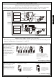
— LARGE COVER
7. Pass the flush pipe and the vacuum
breaker through the guide hole (Step
3) and mount them on the bowl.
8. If required, cut the vacuum breaker
tube to the proper length.
9. Make sure that the o-ring fits in the
groove at the end of the Flush Valve
tailpiece.
NOTE: Exercise care to avoid damaging the
o-ring when inserting the tailpiece
into the control stop. If lubrication is
needed, wet the o-ring with water.
10. Connect the Flush Valve with the control
stop and vacuum breaker tube.
8
ENGLISH
TET2LA32, TET2GA32
TEU2LA12, TEU2UA12
TET2LA31
TET2GA31
TET2LA33
TET2GA33
TEU2LA11, TEU2LA21
TEU2UA11
Bowl or Urinal
Wall surface
6~6-1/2”
(152~165mm)
1-1/2” (38mm)
or 3/4” (19mm)
1-1/2”
(38mm)
5”
(127mm)
2-1/4”~2-3/4”
(57~70mm)
3-3/4”~4-7/8”
(95~124mm)
3-3/4”~4-7/8”
(95~124mm)
Top spud
Back spud
Wall mount
3”
(76mm)
Bowl
3-3/4”~4-7/8”
(95~124mm)
3-3/4”~4-7/8”
(95~124mm)
Urinal
Back spud
Floor mount
Bowl
1-1/2”
(38mm)
1-1/4” (32mm)
or 3/4” (19mm)
7” (178mm) Min space
requirement in wall
Wall surface
Wall surface
Wall surface
7” (178mm) Min space
requirement in wall
7” (178mm) Min space
requirement in wall
7” (178mm) Min space
requirement in wall