
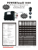
User's Manual


Option 4 - Courtesy Light
Output #7 turns ON for 20-seconds whenever output #1 is activated.
Switch Input A1 controls output #1
Switch Input A2 turns OFF all outputs as long as it is active.
PowerTouch Remote Control Systems - 1000 Series (2 - 6) Functions
Page -2-
ON
OFF
Receiver
1
Operation
Out
# 1
ON
OFF
DIP Switch 7 - OFF
DIP Switch 8 - OFF
DIP Switch 7 - OFF
DIP Switch 8 - ON
Option 2 - Hydraulic Pump
Output #7 is ON anytime outputs 1 - 6 are active.
Switch Input A1 controls output #1
Switch Input A2 controls output #2
DIP Switch 7 - ON
DIP Switch 8 - OFF
Option 3 - Cascade
Output #7 turns ON for 2-seconds whenever output #1 is activated.
Switch Input A1 controls output #1
Switch Input A2 controls output #2
DIP Switch 7 - ON
DIP Switch 8 - ON
DIP Switches 7 & 8
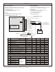
Transmitter Styles
Receiver
Connection
Schematic
DIP switch
located inside
receiver enclosure
Signal Transmissions
Standard - Press & Release Button
No maximum signal duration
Option - Multi-channel signal
Status LED
Standard - One flash per second transmitting
- No flash if low battery
Inputs (DIP switch programmable)
Switch Input A1
Switch Input A2
Outputs (DIP switch programmable)
1 Momentary or Latching
2 Momentary or Latching
3 Momentary or Latching
4 Momentary or Latching
------------------------------------------------------
5 Momentary or Latching
6 Momentary or Latching
7 See DIP Switch Options Below
ENROLLING NEW TRANSMITTERS - Self-Learning Receiver
1. Remove cover from receiver enclosure.
2. Locate LEARN switch (small, square push-button style switch located in the
corner of the printed circuit board).
3. Press and release the LEARN switch and observe LEARN LED (next to
LEARN switch).
4. LED is flashing when unit is in LEARN Mode and new codes can be
enrolled.
5. When LEARN LED is flashing, press any button on transmitter.
6. LEARN LED blinks to confirm enrollment. Release transmitter button.
7. Press any button on the new transmitter to confirm that the new code has
been enrolled.
8. Replace receiver enclosure cover.
Output 7
J2-14
Output 6
J2-13
Output 5
J2-12
Output 4
J2-11
Output 2
J2-9
Output 3
J2-10
Output 1
J2-8
Switch Input A2, J2-2
NO INP BUS, J1-1 (Optional: Typ PWR)
NO INP BUS, J2-6
NO INP BUS, J2-7
Switch Input A1, J2-1
Logic Power, J2-4
Logic Ground, J2-3
DIP Switch Options
ON
OFF
Out
# 3
Out
# 2
Out
# 4
Out
# 5
Out
# 6
2 3 4 5 6 7 8
7 8
ON
OFF
7 8
ON
OFF
7 8
ON
OFF
7 8
ERASING ALL ENROLLED TRANSMITTERS
1. Press and hold the LEARN switch.
2. LEARN LED will flash rapidly for about 10 seconds,
followed by two long flashes.
3. Release LEARN switch.
4. All transmitter codes are now erased.
Optional Enrolling Method
1. Remove and reconnect power to unit. This will place unit
into LEARN mode for 5-seconds.
2. Press any button on transmitter. Wait 5-seconds and confirm
the transmitter has been enrolled by pressing any button and
verifying the correct output turned ON.
4-Relay
Models
7-Relay
Models
DIP Switches 1 - 6 control outputs 1 - 6 respectively:
OFF = Momentary
ON = Latching
LOGIC
Option 1 - Direct Switch Inputs
Switch Input A1 controls output #1
Switch Input A2 controls output #2
Standard - Large Key Fob
2, 4 & 6 Button
Option - Large Oval Hand-Held
2, 4 & 6 Button
(Power Switch Optional)
Option- Small Key Fob
1, 2 & 4 Button
Option - Mini Key Fob
1, 2 & 4 Button
Photos Not To Scale