
User's Manual


SWITCH INPUT A1
SWITCH INPUT A2
CHASSIS GROUND
LOGIC POWER
REVERSAL REST @ GROUND - OPTION
RELAY POWER
OPTIONAL RELAY POWER
CHANNEL 1 - RELAY OUTPUT 1 (RR@G*)
CHANNEL 2 - RELAY OUTPUT 2 (RR@G*)
CHANNEL 3 - RELAY OUTPUT 3 (RR@G*)
CHANNEL 4 - RELAY OUTPUT 4 (RR@G*)
CHANNEL 5 - RELAY OUTPUT 5
CHANNEL 6 - RELAY OUTPUT 6
PROGRAMMABLE OPTION-RELAY OUTPUT 7
POWER - OUTPUTS 1 - 6
GROUND - OUTPUTS 1 - 4 (RR@G*)
SWITCH INPUT B1
SWITCH INPUT B2
SWITCH INPUT B3
SWITCH INPUT B4
SWITCH INPUT B5
SWITCH INPUT B6
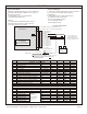
Receiver Installation
Determine installation location of receiver and antenna
- typically under the dash or behind a wall. There are
two types of receivers:
1) Standard Receiver - as pictured below
2) Optional Sealed Receiver
Antennas
A) Fixed Antenna (Installed inside enclosure)
B) Removable 6” Antenna / TNC Connector
C) Exterior Antenna / 14’ Cable
(-)
Vehicle
Battery
(+)
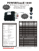
PowerTouch
Remote Control System
1000 Series RF Receiver
#10 Screw
#10 Star Washer
#10 Ring Terminal
Vehicle Frame
Scrape paint and clean area before installing ground screw.
A loose chassis ground connection WILL cause
intermittent operation!
Chassis Ground
2 Amp
Logic Fuse
J2-1
J2-2
J2-3
J2-4
J2-5
J2-6
J2-7
J2-8
J2-9
J2-10
J2-11
J2-12
J2-13
J2-14
J1-1
J1-2
J3-1
J3-2
J3-3
J3-4
J3-5
J3-6
+12V
+12V
GROUND
+12V BATTERY
GROUND
+12V BATTERY
+12V BATTERY
+12V
+12V
+12V
+12V
+12V
+12V
+12V
+12V
GROUND
+12V
+12V
+12V
+12V
+12V
+12V
INPUT
INPUT
INPUT
INPUT
INPUT
INPUT
INPUT
OUTPUT
OUTPUT
OUTPUT
OUTPUT
OUTPUT
OUTPUT
OUTPUT
INPUT
INPUT
INPUT
INPUT
INPUT
INPUT
INPUT
INPUT
N/A
N/A
500mA
500mA
5 A
5 A
5 A
5 A
5 A
5 A
5 A
5 A
5 A
5 A
30 A
30 A
Installation
OPTIONAL J1 POWER CONNECTOR
Antenna Installation
1. The antenna must be installed in an open, non-metal
area in order to receive RF (radio frequency)
transmissions.
2. RF transmissions are reduced if antenna is:
A) within 6 feet of a large motor
B) near large bundles of wires
C) near other RF devices
D) touching any metal
OPTIONAL J3 SWITCH INPUT CONNECTOR
NOTE
Standard:
Switch control 1 - 6.
Fail Safe Option:
Direct relay coil
control 1 - 6.
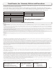
STANDARD J2 CONNECTOR
FUNCTION DESCRIPTIONPIN # VOLTAGE I / OCURRENT
J1
J3
High Current - 30 Amp
(not used in standard installation)
Fixed (standard) or Removable Antenna (optional)
J2 J2-1
J2-2
J2-3
J2-4
J2-5
J2-6
J2-7
J2-8
J2-9
J2-10
J2-11
J2-12
J2-13
J2-14
1
2
3
4
5
6
7
8
9
10
11
12
13
14
SWITCH INPUT A1
SWITCH INPUT A2
GROUND
+12V BATTERY
GROUND*
+12V BATTERY
+12V BATTERY
+12V - OUTPUT # 1
+12V - OUTPUT # 2
+12V - OUTPUT # 3
+12V - OUTPUT # 4
+12V - OUTPUT # 5
+12V - OUTPUT # 6
+12V - OUTPUT # 7
Switch Inputs B1 - B6 (not used in standard installation)
5 Amp
5 Amp
Note: All output circuits
to be appropriately fused
by the installer with 5 Amp
being the maximum fuse size.
Standard Receiver
18 AWG
18 AWG
18 AWG
18 AWG
18 AWG
18 AWG
18 AWG
18 AWG
18 AWG
18 AWG
18 AWG
18 AWG
18 AWG
18 AWG
12 AWG
12 AWG
18 AWG
18 AWG
18 AWG
18 AWG
18 AWG
18 AWG
WHT/RED
GRY/RED
BLK/WHT
RED/WHT
BLK
RED
RED
YEL
ORG
BLU
GRN
PNK
VIO
TAN
RED
BLK
YEL/BLK
ORG/BLK
BLU/BLK
GRN/BLK
PNK/BLK
VIO/BLK
GAUGECOLOR
*Reversal Rest @ Ground
Typical Application
PowerTouch Remote Control Systems - 1000 Series (2 - 6) Functions
Page -3-