User Guide 300Mbps Wireless N Outdoor Access Point CAP300-Outdoor REV1.0.
COPYRIGHT & TRADEMARKS Specifications are subject to change without notice. is a registered trademark of TP-Link Technologies Co., Ltd. Other brands and product names are trademarks or registered trademarks of their respective holders. No part of the specifications may be reproduced in any form or by any means or used to make any derivative such as translation, transformation, or adaptation without permission from TP-Link Technologies Co., Ltd. Copyright © 2017 TP-Link Technologies Co., Ltd..
FCC STATEMENT This equipment has been tested and found to comply with the limits for a Class B digital device, pursuant to part 15 of the FCC Rules. These limits are designed to provide reasonable protection against harmful interference in a residential installation. This equipment generates, uses and can radiate radio frequency energy and, if not installed and used in accordance with the instructions, may cause harmful interference to radio communications.
This is a class B product. In a domestic environment, this product may cause radio interference, in which case the user may be required to take adequate measures. RF Exposure Information This device meets the EU requirements (1999/5/EC Article 3.1a) on the limitation of exposure of the general public to electromagnetic fields by way of health protection. The device complies with RF specifications when the device used at 20 cm from your body.
NCC Notice 注意! 依據 低功率電波輻射性電機管理辦法 第十二條 經型式認證合格之低功率射頻電機,非經許可,公司、商號或使用者均不得擅自 變更頻率、加大功率或變更原設計之特性或功能。 第十四條 低功率射頻電機之使用不得影響飛航安全及干擾合法通行;經發現有干擾現象時, 應立即停用,並改善至無干擾時方得繼續使用。前項合法通信,指依電信規定作業之無線電 信。低功率射頻電機需忍受合法通信或工業、科學以及醫療用電波輻射性電機設備之干擾。 BSMI Notice 安全諮詢及注意事項 請使用原裝電源供應器或只能按照本產品注明的電源類型使用本產品。 清潔本產品之前請先拔掉電源線。請勿使用液體、噴霧清潔劑或濕布進行清潔。 注意防潮,請勿將水或其他液體潑灑到本產品上。 插槽與開口供通風使用,以確保本產品的操作可靠並防止過熱,請勿堵塞或覆蓋開口。 請勿將本產品置放於靠近熱源的地方。除非有正常的通風,否則不可放在密閉位置中。 請不要私自打開機殼,不要嘗試自行維修本產品,請由授權的專業人士進行此項工作。 Продукт сертифіковано згідно с прави
Use only power supplies which are provided by manufacturer and in the original packing of this product. If you have any questions, please don't hesitate to contact us. Explanation of the symbols on the product label Symbol Explanation DC voltage RECYCLING This product bears the selective sorting symbol for Waste electrical and electronic equipment (WEEE).
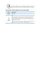
CONTENTS About this User Guide............................................................................................................................ 1 Introduction ...................................................................................................................... 2 Working Mode.................................................................................................................. 3 FIT Mode..................................................................................
About this User Guide When using this guide, please notice that features of the CAP may vary slightly depending on the model and software version you have, and on your location, language, and Internet service provider. All screenshots, images, parameters and descriptions documented in this guide are used for demonstration only. The information in this document is subject to change without notice.
Introduction Auranet series products provide wireless coverage solutions for small-medium business. They can either work independently in FAT mode or be centrally managed by the wireless controller in FIT mode, providing a flexible, richly-functional but easily- configured enterprise-grade wireless network for small and medium business.
Working Mode CAPs support two working modes including FIT mode and FAT mode. In FIT mode, APs can be centrally managed by TP-Link’s wireless controller. The default FIT mode is used when you want to deploy a large wireless network. The management of every single AP in the network is complex and complicated. With the wireless controller, you can centrally manage the mass APs simply in a web browser. In FAT mode, you can log in to AP’s webpage to manage the AP alone.
Typical topology in FIT mode: Figure 2-1 Typical Topology in FIT Mode NOTE: The IP address of the wireless controller must be reachable for the CAPs in the network.
FAT Mode In FAT mode, you can log in to AP’s webpage to manage the AP alone. The FAT mode is used in a small wireless network.
Follow the steps below to log in to the web interface. 1. Launch a web browser, enter 192.168.0.254 in the address field and press the Enter key. NOTE: To log in to the device, the IP address of your PC should be set in the same subnet addresses of the device. The IP address is 192.168.0.x (”x” is any number from 1 to 253). Subnet Mask is 255.255.255.0. 2. Create a new username and password for login, and then click OK. Figure 2-3 Login 3. The webpage will be shown as below.
Figure 2-4 Status TIPS: Proceed to the following chapters for information on configuring the CAP in FAT mode.
Status The Status page displays the device information, wireless parameter, wireless service and wireless client of the CAP. Figure 3-1 Status Page Device Information This section displays the information of hardware version, MAC address, IP address, system time and running time of the CAP. If you want to modify the IP address of the CAP, Please refer to AP Management. To modify the system time, please refer to Time Setting.
mode, channel bandwidth and channel frequency and refer to WDS Settings to configure the WDS feature. Figure 3-3 Wireless Parameter Wireless Service In this section, you can check or edit the wireless service information of the CAP. Figure 3-4 Wireless Service Click the button to edit the corresponding wireless service entry. You can change the SSID, Network type and password. Check or uncheck the status box to enable or disable the wireless service as needed.
Wireless Client The wireless client table displays the information of the connected clients including their MAC address, connected SSID and the connection time.
Wireless Wireless page consists of Wireless, WDS Settings and Advanced Settings. Figure 4-1 Wireless Page If you have made any change of the parameters, please click OK to make the configuration take effect. There will be a blue bar at the top of the page to remind you to save the configuration. Click Save when you finish all settings, otherwise all the settings will be recovered to last saved settings at reboot or power off.
Figure 4-2 Wireless Click Add to create a new wireless service. Click button wireless service. SSID: to edit the corresponding Enter a character string no more than 32 characters to name your wireless network. We suggest you to set an easy-to-remember SSID to conveniently identify your wireless network. Check the box of Enable Broadcast to allow this device to broadcast its SSID. Therefore, the hosts within its wireless coverage could find the wireless signals.
Enable Wireless Network: Check the box to enable this wireless network, allowing the hosts connected to the wireless network to communicate with each other. Security Mode Following is the detailed introduction of security mode: WPA/WPA2 and WPA-PSK/WPA2PSK. WPA-PSK/WPA2-PSK Based on pre-shared key. It is characterized by higher safety and simple settings, which suits for common households and small business. WPA-PSK has two versions: WPAPSK and WPA2-PSK.
Based on Radius Server, WPA can assign different password for different users and it is much safer than WPA-PSK. However, its maintenance costs much which is only suitable for enterprise users. At present, WPA has two versions: WPA and WPA2. Figure 4-4 Security Mode WPA/WPA2 Authentication Type: Select one of the following versions: Auto: Select WPA-PSK or WPA2-PSK automatically based on the wireless station's capability and request. WPA: Wi-Fi Protected Access. WPA2: Version 2 of WPA.
system, only data frames with four address fields can be transparently forwarded at the link layer. In a WDS network, it is necessary that the root AP supports forwarding of data frames four address fields. If not, only data frames with the ARP/IP/PPPOE protocol can be forwarded among APs. Figure 4-5 WDS Settings Check the box and click OK. The following figure will be shown. Click Yes to enable the WDS feature. There are two ways to select the root AP. Scan or manually enter the parameters.
Figure 4-7 WDS Settings Manually You should manually enter the parameters of the root AP. Click OK to finish the settings. WDS: Check the box to enable WDS feature. SSID: The SSID of the AP your device is going to connect to as a client. BSSID: The BSSID of the AP your device is going to connect to as a client. Security Mode: This option should be chosen according to the AP's security configuration. It is recommended that the security type is the same as your AP's security type.
It is recommended to select 802.11b/g/n, in which way clients supporting any one of these modes can access your wireless network. Channel Bandwidth: Select the channel bandwidth of this device including 20MHz and 40MHz. The default setting is Auto, which will select the proper bandwidth automatically according to the network need. According to IEEE 802.11n standard, using a higher bandwidth can increase wireless throughput. However, users may choose lower bandwidth due to the following reasons: 1.
Discard stations with a signal strength lower than ( ) dBm: Enable or disable the discard rules. Set the minimum signal strength in which the AP will discard a connected client. Values from -95 to 0 dBm are valid. The default value is -75dBm. It is recommended the maximum number is less than -40 dBm. When the signal strength of the connected client is lower than the threshold value (for example due to obstacles or long distances), the client will be discarded by the AP.
Network On Network page, you can configure the wireless MAC filtering rule and set the VLANs. Figure 5-1 Network Page If you have made any change of the parameters, please click OK to make the configuration take effect. There will be a blue bar at the top of the page to remind you to save the configuration. Click Save when you finish all settings, otherwise all the settings will be recovered to last saved settings at reboot or power off.
Figure 5-3 Filtering Rule MAC Address: Enter the MAC address of the client. Effective Range: Select the wireless network that allows the client to access. Description: Specify a description for the entry to make it easier to search for and manage. Click button to modify the corresponding entry and click button to delete the selected entry. VLAN Settings In this section, all the wireless network will be listed here.
System System page is mainly used to configure some basic information like AP management, user account, system log, time setting, and realize functions including reboot, reset, backup, restore, firmware upgrade and ping watch dog. Figure 6-1 System Page If you have made any change of the parameters, please click OK to make the configuration take effect. There will be a blue bar at the top of the page to remind you to save the configuration.
AP Management You can change the IP address, mask, default gateway, web service port and web session timeout of the CAP and enable the manage VLAN. Figure 6-2 AP Management Page IP Address: Set the IP address through which the hosts in the LAN can visit the CAP. The default setting is 192.168.0.254. You can change the IP according to the network need. Mask: Set the mask of CAP. The default setting is 255.255.255.0. You can change it according to the network need.
Web Session Timeout: Set the session timeout for the webpage. When you log in to the CAP’s webpage, if there is no operation during the set time, the webpage will be logged out automatically. Account You can change the username and password to protect your device from unauthorized login. Figure 6-3 Account Page Current User Name/Password: Enter the current user name and password of the admin account to get the permission of modification.
Figure 6-4 System Log Check Log: Click Open to check the system log. Download Log: Click Download to download the system log. Send To Server/ Server Address: Check the box to enable the function. If you want to check the system log in a specified host, please install a system log server and enter the server IP in this field. Click OK, then the AP will send the system log to the specified IP address. Time Setting System time represents the device system’s notion of the passing of time.
Time: Specify the device’s time. Select the number from the drop-down list in time format HH/MM/SS. NTP Server I/NTP Server II: Please input the primary NTP sever address and an alternative NTP server address. Configuration Management In this section, you can backup, restore, reset or reboot your CAP. Figure 6-6 Configuration Management Backup: Click Backup to save a copy of your current settings. Please save your copy in a secure file location.
Figure 6-8 Firmware Upgrade Hardware Version: Display the current hardware version. Firmware Version: Display the current Firmware version. Firmware Upgrade: Click Browse to locate and select the firmware file. Click Upload to upload the file to upgrade. Do NOT power off your device while it is upgrading. Ping Watch Dog Ping Watch Dog sets the device to continuously ping a user-defined IP address (it can be the Internet gateway, for example) to check the network connectivity.
Start-up Delay: Enter the initial time delay (in seconds) from device startup to the first ICMP echo requests sent by Ping Watch Dog. The default value is 300 seconds. The Startup Delay value should be at least 60 seconds as the device’s initialization takes a considerable amount of time. Lost Packets Count: Enter the fail count of ICMP echo request.