Installation Guide Outdoor CPE CPE210 / CPE220 / CPE510 / CPE520
Contents Overview 01 Hardware Connection 04 Connection and Installation 06 Site Consideration Lightning & ESD Protection Software Configuration Logging in to the PharOS Typical Application Configuration 04 08 10 10 12 Antenna Alignment 14 Specifications 15 FAQ 16
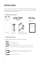
Overview TP-Link's Pharos series outdoor CPEs are dedicated to outdoor wireless network solutions. This guide is applicable to products including CPE210, CPE220, CPE510 and CPE520. • Package Contents Power Cord Pole Mounting Straps Installation Guide Outdoor CPE CPE210 / CPE220 / CPE510 / CPE520 Pharos CPE Passive PoE Adapter Mounting Bracket Plastic Wall Anchors (Qty.2) Self-tapping Screws (Qty.2) Installation Guide • LED Explanation The following picture takes CPE520 as an example.
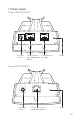
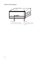
• Panel Layout Pharos CPE220/CPE520: Grounding Terminal Shielded Ethernet Port LAN0 (Passive PoE in) Shielded Ethernet Port LAN1 RESET Pharos CPE210/CPE510: Grounding Terminal Shielded Ethernet Port LAN (Passive PoE in) RESET 02
Passive PoE Adapter: Remote Reset Press and hold for 8 seconds to reset the CPE to its factory defaults. 03 Power LED The Power LED is on when the passive PoE adapter is working normally.
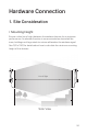
Hardware Connection 1. Site Consideration • Mounting Height Ensure a clear line of sight between the wireless devices for an optimum performance. An elevated location is recommended as obstacles like trees, buildings and large steel structures will weaken the wireless signal. See 'Q2' in 'FAQ' for details about how to calculate the minimum mounting height of the devices.
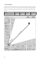
• Orientation Install the CPE devices with the front facing the intended signal receiving devices. You can orient the devices with the assistance of Google Maps, GPS and some landmarks according to the horizontal beamwidth listed below.
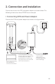
2. Connection and Installation Connect and mount the CPE and power adapter as shown below. The following introduction takes CPE520 as an example. • Connecting CPE and Power Adapter Connect the CPE and power adapter as shown in the figure below. LAN0 PoE LAN Ethernet cable length up to 60m Slide to replace the cover of the CPE when all connections are finished. You should prepare an adequate Ethernet cable to connect the CPE and the passive PoE adapter.
• Mounting CPE At the selected site, approximately align the CPE to the direction that you have oriented. • Mounting Power Adapter (Optional) Follow the steps below to mount the power adapter: 1. 2. 07 To ensure the passive PoE adapter is attached most securely, it is recommended to install the adapter with the Ethernet port facing upward. Drill two holes on the wall and insert the plastic wall anchors into the the holes. Secure the mounting bracket to the wall.
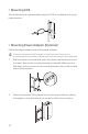
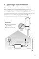
3. Lightning & ESD Protection Proper grounding is extremely important for outdoor devices. By using shielded CAT5e (or above) cable with ground wire for the connection and the provided PoE adapter (method 1 ), you can effectively eliminate ESD attacks. If you use the general CAT5e cable for the connection, then it is necessary to connect the grounding terminal of the CPE to earth ground through grounding cable (method 2 ). The following introduction takes CPE520 as an example.
Sheath Twisted Pair Ground Wire Cable Shield Secondary Cable Shield Shielded RJ45 Connector Shielded CAT5e (or above) Cable with Ground Wire 09
Software Configuration This chapter introduces the login to the PharOS Web Interface and the software configurations. 1. Logging in to the PharOS 1. Before accessing the PharOS Web Interface, you need to assign a static IP address 192.168.0.X (X ranges between 2 and 253, e.g. 192.168.0.10) to your computer. 2. Open a web browser, type http://192.168.0.254 into the address field and press Enter (Windows) or return (Mac). It is recommended to use the latest version of Google Chrome, Firefox or Safari.
3. Enter admin for both User Name and Password. Read and agree the terms of use, then click Login. 4. Change the default User Name and Password to protect your CPE. Let’s start configuring the CPE. For subsequent logins, use the new username and password. For more configurations, please visit http://www.tp-link.com/support to download the User Guide of PharOS products in the download center.
2. Typical Application Configuration The typical topology is as follows. A wireless bridge is built between two locations that are far from each other. Follow the instructions below to configure the Access Point and the Client. IP camera Computer Access Point LAN: 192.168.0.254 Client LAN: 192.168.0.2 Configure the Access Point (AP) 1. Log in to PharOS and go to the Quick Setup page. 2. Operation Mode: Select Access Point and click Next. 3. LAN Settings: Click Next. 4. Wireless AP Settings: a.
3. LAN Settings: Change the IP Address to 192.168.0.X (X ranges between 2 and 253), the same subnet with the access point, and click Next. 4. Wireless Client Settings: a. Click Survey and select the SSID of the Access Point in the AP list, then click Connect. b. Select WPA-PSK/WPA2-PSK from the Security option, enter the same PSK password and distance value of the Access Point, then click Next. 5. Finish: Verify your settings and click Finish to complete the configuration.
Antenna Alignment In order to get the best performance, you can precisely align the direction of the CPE with the assistance of Wireless Signal Quality on STATUS page of the PharOS Web Interface. Adjust the direction of the CPE until the device reaches the highest SNR.
Carrier Sense Specifications HARDWARE FEATURES Dimensions CPE520/CPE220: 275.83*79*60.3mm CPE510/CPE210: 224.34*79*60.
FAQ Q1. How to restore the CPE to its factory default settings? With the CPE powered on, press and hold the RESET button on the CPE or the Remote Reset button on the passive PoE adapter for about 8 seconds until the Wireless Signal Strength LEDs flash. Method 1: The following picture takes CPE520 as an example.
Q2. How to calculate the minimum mounting height of the devices? In order to maximize the received signal strength of the devices, installers need to minimize the effect of the out-of-phase signals, which is caused by obstacles in the path between the transmitter and the receiver. Fresnel Zone is a usual method to calculate this path, as shown in the formula and the figure below.
Q3. What is Pharos MAXtream? Pharos MAXtream is a proprietary protocol developed on the basis of Time Division Multiple Access (TDMA) by TP-Link. The MAXtream technology has the following advantages: • Eliminates hidden node collisions & improves channel efficiency. • Lower latency, higher throughput, larger network capacity & more stability. • Improves the QoS for video, voice and sound data stream.
average curve indicates less radio noise. Here, we use the figure below as an example. The select box of Frequency Range at the top-left corner is only available for CPE510 and CPE520. Select the desired range and then click Start. When choosing channel/frequency, you should avoid the spectrum with large radio noise. In this example, the recommended channel/ frequency is 112/5560MHz.
FCC STATEMENT (For CPE220/CPE510/CPE520) This equipment has been tested and found to comply with the limits for a Class A digital device, pursuant to part 15 of the FCC Rules. These limits are designed to provide reasonable protection against harmful interference when the equipment is operated in a commercial environment.
FCC RF Radiation Exposure Statement: This equipment complies with FCC RF radiation exposure limits set forth for an uncontrolled environment. This device and its antenna must not be co-located or operating in conjunction with any other antenna or transmitter. “To comply with FCC RF exposure compliance requirements, this grant is applicable to only Mobile Configurations.
Canadian Compliance Statement This device complies with Industry Canada license-exempt RSSs. Operation is subject to the following two conditions: 1) This device may not cause interference, and 2) This device must accept any interference, including interference that may cause undesired operation of the device. Le présent appareil est conforme aux CNR d’Industrie Canada applicables aux appareils radio exempts de licence.
Safety Information • Keep the device away from water, fire, humidity or hot environments. • Do not attempt to disassemble, repair, or modify the device. • Do not use damaged charger or USB cable to charge the device. • Do not use any other chargers than those recommended • Do not use the device where wireless devices are not allowed. • Adapter shall be installed near the equipment and shall be easily accessible.
Продукт сертифіковано згідно с правилами системи УкрСЕПРО на відповідність вимогам нормативних документів та вимогам, що передбачені чинними законодавчими актами України. Explanation of the symbols on the product label Symbol Explanation DC voltage RECYCLING This product bears the selective sorting symbol for Waste electrical and electronic equipment (WEEE).