Installation Guide Outdoor CPE CPE210 / CPE220 / CPE510 / CPE520
CONTENTS Overview 1 Hardware Connection Site Consideration Connection and Installation Lightning & ESD Protection 3 5 6 Software Configuration Logging into the PharOS Configuration for Typical Applications • Point-to-Point 8 11 11 Antenna Alignment 15 Specifications 16 FAQ (Frequently Asked Questions) 17
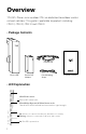
Overview TP-LINK's Pharos series outdoor CPEs are dedicated to outdoor wireless network solutions. This guide is applicable to products including CPE210, CPE220, CPE510 and CPE520. • Package Contents Power Cord Pharos CPE Passive PoE Adapter Pole Mounting Straps Installation Guide • LED Explanation AP/AP Router mode: All four LEDS remain solid. Client/Bridge/Repeater/AP Client Router mode: That the more LEDs lit will indicate better wireless signal strength.
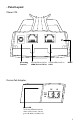
• Panel Layout Pharos CPE: Grounding Terminal Shielded Ethernet Port LAN0 (Passive PoE in) Shielded Ethernet Port LAN1 RESET Passive PoE Adapter: Power LED The Power LED indicates the status of the electric current: green (0~0.8A), red (0.8A~1A).
Hardware Connection 1. Site Consideration • Mounting Height Ensure a clear line of sight between the wireless devices for an optimum performance. An elevated location is recommended as obstacles like trees, buildings and large steel structures will weaken the wireless signal. See 'Q2' in 'FAQ' for details about how to calculate the minimum mounting height of the devices.
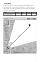
• Orientation Install the CPE devices with the front facing the intended signal receiving devices. You can orient the devices with the assistance of Google Maps, GPS and some landmarks according to the horizontal beamwidth listed below.
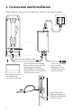
2. Connection and Installation 5734 MADE IN CHINA Password: admin 5GHz 300Mbps 13dBi Outdoor CPE Power: 24V 1A Model: CPE510 Default Settings: IP: 192.168.0.254 Username: admin This device complies with part 15 of the FCC Rules. Operation is subject to the following two conditions:(1) This device may not cause harmful interference,and (2) this device must accept any interference received, including interference that may cause undesired operation.
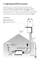
3. Lightning & ESD Protection Proper grounding is extremely important for outdoor devices. By using shielded CAT5e (or above) cable with ground wire for the connection and the provided PoE adapter (method 1 ), you can effectively eliminate ESD attacks. If you use the general CAT5e cable for the connection, then it is necessary to connect the grounding terminal of the CPE to earth ground through grounding cable (method 2 ).
Sheath Twisted Pair Ground Wire Cable Shield Secondary Cable Shield Shielded RJ45 Connector Shielded CAT5e (or above) Cable with Ground Wire 7
This chapter introduces the login to the PharOS Web Interface and including point-to-point and hotspot. 1. Logging into the PharOS 1. Before accessing the PharOS Web Interface, you need to assign a static IP address 192.168.0.x (2≤x≤253) to your computer.
2. Open your web browser, type 'http://192.168.0.254' in the address field and press 'Enter'. It is recommended to use the latest version of Google Chrome, Safari or Firefox. 3. The 'Login' page will appear, set the parameters as below. • Username: admin. • Password: admin. • Select 'I agree to these terms of use'. • Click 'Login'. 4. At the first login, change the 'Password' for safety. For subsequent logins, you only need to enter the username and password that you have set to log in.
5. Then you will log in to the PharOS Web Interface and see the Status page as shown in the figure below.
2. and hotspot applications. Refer to the section corresponding to your networking needs. • Point-to-Point Point-to-Point application is used to build a transparent bridge below is an example for this application. IP camera Computer Access Point LAN: 192.168.0.254 Client LAN: 192.168.0.2 1. Log in to PharOS 2. Go to the Quick Setup page 3. Operation Mode Select 'Access Point'. Click 'Next'. 4. LAN Settings: Click 'Next'. 5. Wireless AP Settings SSID: customize the name for the network as you like.
Antenna Alignment In order to get the best performance, you can precisely align the direction of the CPE with the assistance of 'Wireless Signal Quality' on 'STATUS' page of the PharOS Web Interface. Adjust the direction of the CPE until the device reaches the highest SNR.
HARDWARE FEATURES Power Supply CPE520/CPE220: 275.83*79*60.3mm CPE510/CPE210: 224.34*79*60.
FAQ (Frequently Asked Questions) Q1. How to restore the CPE to its factory default settings? With the CPE powered on, press and hold the 'RESET' button of the CPE or the 'Remote Reset' button of the passive PoE adapter for about 8 seconds until the Wireless Signal Strength LEDs flash.
Q2. How to calculate the minimum mounting height of the devices? In order to maximize the received signal strength of the devices, installers need to minimize the effect of the out-of-phase signals, which is caused by obstacles in the path between the transmitter and the receiver. Fresnel Zone is a usual method to calculate this path, as shown in the formula and the figure below.
Q3. How can I use Spectrum Analysis to find the appropriate channel for the devices? 1. Log in to PharOS, on the 'WIRELESS' page, you can find the 'Spectrum Analysis' button as shown in the figure below. Click the button. 2. The following window will pop up. Click 'Yes' and you will then get into the 'Spectrum Analysis' page. 3. Select the 'Frequency Range' and click the 'Start' button, the PharOS will begin to analyze the power of the frequency.
4. Close the Spectrum Analysis Window, and then you will get back to the 'WIRELESS' page. For the Channel/Frequency option, it is recommended to select a value whose frequency is within the noted frequency range. So, in this example, the recommended Channel/Frequency is 116/5580MHz. Q4. What is Pharos MAXtream? Pharos MAXtream is a proprietary protocol developed on the basis of Time Division Multiple Access (TDMA) by TP-LINK.
FCC STATEMENT This equipment has been tested and found to comply with the limits for a Class A digital device, pursuant to part 15 of the FCC Rules. These limits are designed to provide reasonable protection against harmful interference when the equipment is operated in a commercial environment. This equipment generates, uses, and can radiate radio frequency energy and, if not installed and used in accordance with the instruction manual, may cause harmful interference to radio communications.
Safety Information • When product has power button, the power button is one of the way to shut off the product; When there is no power button, the only way to completely shut off power is to disconnect the product or the power adapter from the power source. • Don’t disassemble the product, or make repairs yourself. You run the risk of electric shock and voiding the limited warranty. If you need service, please contact us. • Avoid water and wet locations.
Industry Canada statement: This device complies with RSS-247 of the Industry Canada Rules. Operation is subject to the following two conditions: (1) This device may not cause harmful interference, and (2) this device must accept any interference received, including interference that may cause undesired operation. Ce dispositif est conforme à la norme CNR-247 d'Industrie Canada applicable aux appareils radio exempts de licence.
Professional installation instruction 1. Installation personal This product is designed for specific application and needs to be installed by a qualified personal who has RF and related rule knowledge. The general user shall not attempt to install or change the setting. 2. Installation location The product shall be installed at a location where the radiating antenna can be kept 26cm from nearby person in normal operation condition to meet regulatory RF exposure requirement. 3.
COPYRIGHT & TRADEMARKS Specifications are subject to change without notice. is a registered trademark of TP-LINK TECHNOLOGIES CO., LTD. Other brands and product names are trademarks or registered trademarks of their respective holders. No part of the specifications may be reproduced in any form or by any means or used to make any derivative such as translation, transformation, or adaptation without permission from TP-LINK TECHNOLOGIES CO., LTD. Copyright © 2014 TP-LINK TECHNOLOGIES CO., LTD.