Installation Guide Outdoor CPE CPE610
Contents Overview 1 Package Contents Hardware Overview Hardware Connection 4 Site Consideration Hardware Installation Power Supply Lightning & ESD Protection Software Configuration 15 Logging in to the PharOS Configuration for a Typical Application Antenna Alignment 18 Specifications 19 FAQ 20
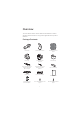
Overview TP-Link's Pharos series outdoor CPEs are dedicated to outdoor wireless network solutions. This guide is applicable to the product CPE610. Package Contents Pharos CPE Center Reflector Panel Side Reflector Panels (Qty.2) Rear Cover Mounting Bracket (For CPE) Protective Cap Bolts with Nut and Lock Washer Assemblies (M6×110, Qty.
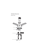
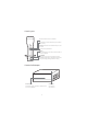
Hardware Overview Bottom View Reflector Assembly Securing Arms Bubble Level Rear Cover Mounting Bracket Pole-mount Clamp 2
Panel Layout On: The wireless function is enabled. On: A device is connected to this port, but there is no activity. Flashing: A device is connected to this port, and is active. On: The CPE is powered on. RESET Press and hold for 5 seconds to reset the CPE to its factory defaults. ETHERNET The port is to connect to the POE port of the provided PoE adapter for both data transmission and power supply through Ethernet cabling.
Hardware Connection Site Consideration Mounting Height Ensure a clear line of sight between the wireless devices for optimum performance. An elevated location is recommended as obstacles like trees, buildings and large steel structures will weaken the wireless signal. See 'Q2' in 'FAQ' for details about how to calculate the minimum mounting height of the devices.
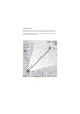
Orientation Install the CPE devices so that they point towards the devices that will receive the signal. You can orient the devices with the help of Google Maps, GPS and some landmarks. The horizontal bandwidth of CPE610 is 6.8°.
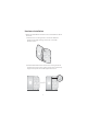
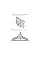
Hardware Installation 1. Attach the Side Reflector Panels to the Center Reflector Panel as follows: a. Insert the two mounting studs on the Center Reflector Panel into the large opening of the slots on the Side Reflector Panel. b. Slide the Side Reflector Panel until the mounting studs are positioned over the narrow opening of the slots, and the top edges of the panels should be aligned when done.
c. Repeat step a and step b to attach the other Side Reflector Panel. d. (Optional) Attach the Side Reflector Panels to the Center Reflector Panel more securely using four M2.5x8 bolts and nuts (not provided). This is recommended if the CPE device is exposed to extreme weather, such as strong winds. 2. Attach the Rear Cover to the reflector assembly as follows: a.
b. Attach the Rear Cover to the reflector assembly. Press upon the Rear Cover at the four positions marked in the diagram below in sequence until it locks into place. 1 2 3 4 WARNING: To avoid damage, do not place the panels on a flat surface or push down on it.
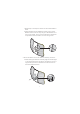
3. Insert the Pharos CPE into the Rear Cover until the CPE locks into place. 4. Connect the Ethernet cable to the Pharos CPE. a. Connect the Ethernet cable to the Ethernet port. Note: The length of the Ethernet cable is up to 60m for steady power supply.
b. Attach the Protective Cap to the Rear Cover. 5. Attach the Mounting Bracket to the Rear Cover until the grooves on the Mounting Bracket are positioned over the pins on the Rear Cover.
6. Secure the Mounting Bracket to the Rear Cover using M6x70 Bolts with Nut and Lock Washer Assemblies. 7. Attach the CPE assembly to the pole using two Pole-mount Clamps and two M6x110 Bolts with Nut and Lock Washer Assemblies. a. Insert the two Bolts into the Mounting Bracket.
b. Secure the Pole-mount Clamps with Nuts and Washers. Note: Suitable pole diameters range from 15mm to 70mm. 8. Adjust the azimuth and elevation angle of the CPE device to achieve maximum signal strength.
Power Supply Connecting the PoE Adapter Connect the devices as shown in the figure below. PoE LAN Ethernet cable length up to 60m Mounting the PoE Adapter (Optional) Note: To ensure the passive PoE adapter is attached most securely, it is recommended to install the adapter with the Ethernet port facing upward. 1. Drill two holes on the wall 2. Attach the passive PoE and insert the plastic wall adapter to the mounting anchors into the the holes.
Lightning & ESD Protection Proper grounding is extremely important for outdoor devices. By using shielded CAT5e (or above) cable with ground wire and the provided PoE adapter, you can effectively eliminate ESD attacks.
6RIWZDUH &RQƮJXUDWLRQ This chapter introduces the login to the PharOS Web Interface and the software configurations. Logging in to the PharOS 1. Before accessing the PharOS Web Interface, you need to assign a static IP address 192.168.0.X (X ranges between 2 and 253, e.g. 192.168.0.10) to your computer. 2. Open a web browser, type http://192.168.0.254 into the address field and press Enter (Windows) or return (Mac). It is recommended to use the latest version of Google Chrome, Firefox or Safari. 192.168.
4. Change the default User Name and Password for security purposes. You can then start to configure your CPE. For subsequent logins, use the new username and password. For more configurations, please visit http://www.tp-link.com/support to download the User Guide of PharOS products in the download center. &RQƮJXUDWLRQ IRU D 7\SLFDO $SSOLFDWLRQ The typical topology is as follows: Multiple wireless bridges are built among the access point and the clients.
c. Enter the distance between the Access Point and the Client into the Distance Setting field. d. Select the MAXtream checkbox (Refer to Q3 in FAQ for details about MAXtream), and click Next. 5. Finish: Verify your settings and click Finish to complete the configuration. &RQƮJXUH WKH &OLHQW 1. Log in to PharOS and go to the Quick Setup page. 2. Operation Mode: Select Client and click Next. 3. LAN Settings: Change the IP Address to 192.168.0.
$QWHQQD $OLJQPHQW In order to get the best performance, you can precisely align the direction of the CPE with the assistance of Wireless Signal Quality on the STATUS page of the PharOS Web Interface. Adjust the direction of the CPE until the SNR reaches a maximum.
6SHFLƮFDWLRQV HARDWARE FEATURES Interface LAN: 10/100Mbps Ethernet port RESET: Button to restore the device to its factory defaults Power Supply 24V passive PoE adapter included ESD Protection 1 15kV Lightning Protection 1 Up to 6kV Operating Temperature -40℃ to 70℃ (-40℉ to 158℉) Operating Humidity 10% to 90% &HUWLƮFDWLRQ CE, FCC, RoHS, IP65 WIRELESS FEATURES Antenna Gain 20.8dBi Vertical-Polarization Port Azimuth Beamwidth: 8.9° Elevation Beamwidth: 7.
)$4 Q1. How to restore the CPE to its factory default settings? With the CPE powered on, press and hold the RESET button on the CPE or the Remote Reset button on the passive PoE adapter for about 5 seconds.
Q2. How to calculate the minimum mounting height of the devices? In order to maximize the received signal strength of the devices, you need to minimize the effect of the out-of-phase signals, which is caused by obstacles in the path between the transmitter and the receiver. Fresnel Zone is a usual method to calculate this path, as shown in the formula and the figure below.
Q3. What is Pharos MAXtream? Pharos MAXtream is a proprietary protocol developed on the basis of Time Division Multiple Access (TDMA) by TP-Link. The MAXtream technology has the following advantages: Eliminates hidden node collisions & improves channel efficiency. Lower latency, higher throughput, larger network capacity & more stability. Improves the QoS for video, voice and sound data stream.
2. Click Start, PharOS will begin to analyze the power of frequency. Observe the curves for a period of time, and then click Stop. Note that the relatively low and continuous part of the average curve indicates less radio noise. Here, we use the figure below as an example. 3. When choosing channel/frequency, you should avoid the spectrum with large radio noise. In this example, the recommended channel/ frequency is 112/5560MHz.
)&& 67$7(0(17 This equipment has been tested and found to comply with the limits for a Class A digital device, pursuant to part 15 of the FCC Rules. These limits are designed to provide reasonable protection against harmful interference when the equipment is operated in a commercial environment. This equipment generates, uses, and can radiate radio frequency energy and, if not installed and used in accordance with the instruction manual, may cause harmful interference to radio communications.
цѧѥћѪѡѩ ѨќѧѩџѫѽѡѥљїѤѥ ўњѽћѤѥ Ѩ ѦѧїљџѢїѣџ ѨџѨѩќѣџ ъѡѧшмцчх Ѥї љѽћѦѥљѽћѤѽѨѩѳ љџѣѥњїѣ ѤѥѧѣїѩџљѤџѬ ћѥѡѪѣќѤѩѽљ ѩї љџѣѥњїѣ Ѱѥ ѦќѧќћјїѮќѤѽ ѮџѤѤџѣџ ўїѡѥѤѥћїљѮџѣџ їѡѩїѣџ ъѡѧїѾѤџ Safety InfRUPation • Keep the device away from water, fire, humidity or hot environments. • Do not attempt to disassemble, repair, or modify the device. • Do not use damaged charger or USB cable to charge the device. • Do not use any other chargers than those recommended. • Do not use the device where wireless devices are not allowed.
For technical support, User Guide and other information, please visit http://www.tp-link.com/support, or simply scan the QR code. The products of TP-Link partly contain software code developed by third parties, including software code subject to the GNU General Public License (“GPL”). As applicable, the terms of the GPL and any information on obtaining access to the respective GPL Code used in TP-Link products are available to you in GPL-Code-Centre under (http://www.tp-link.com/en/support/gpl/).