Archer D20 User Guide AC750 Wireless Dual Band ADSL2+ Modem Router REV1.0.
Contents About This Guide . . . . . . . . . . . . . . . . . . . . . . . . . . . . . . . . . . . . . . . . . . . . . . . . . . 1 Chapter 1. Get to Know About Your Modem Router . . . . . . . . . . . . . . . . . 2 1. 1. 1. 2. 1. 3. Product Overview . . . . . . . . . . . . . . . . . . . . . . . . . . . . . . . . . . . . . . . . . . . . . . . . . . . . . . . . . . 3 Main Features . . . . . . . . . . . . . . . . . . . . . . . . . . . . . . . . . . . . . . . . . . . . . . . . . . . . . . . . . . . . . .
8. 2. 8. 1. 2.Customize Your Settings. . . . . . . . . . . . . . . . . . . . . . . . . . . . . . . . . . . . . . . . . . . . . 32 Remote Access via FTP Server. . . . . . . . . . . . . . . . . . . . . . . . . . . . . . . . . . . . . . . . . . . . . . 35 8. 2. 1.Access the USB disk . . . . . . . . . . . . . . . . . . . . . . . . . . . . . . . . . . . . . . . . . . . . . . . . . 35 8. 3. 8. 2. 2.Customize Your Settings. . . . . . . . . . . . . . . . . . . . . . . . . . . . . . . . . . . . . . . . . . . . .
Chapter 13. Administrate Your Network . . . . . . . . . . . . . . . . . . . . . . . . . . . . 78 13. 1. 13. 2. 13. 3. 13. 4. 13. 5. 13. 6. 13. 7. 13. 8. 13. 9. 13. 10. Set System Time . . . . . . . . . . . . . . . . . . . . . . . . . . . . . . . . . . . . . . . . . . . . . . . . . . . . . . . . . 79 Update the Firmware . . . . . . . . . . . . . . . . . . . . . . . . . . . . . . . . . . . . . . . . . . . . . . . . . . . . . . 80 Back up and Restore Configuration Settings . . . . . . . . . . . . . . . . . .
About This Guide This guide provides details of each function and shows how to configure the modem router appropriate to your needs. In addition to this guide, a Quick Installation Guide is also released with each TP-LINK modem router, you are suggested to configure your modem router for quick Internet setup by following the published Quick Installation Guide before you get started with a further configuration.
Chapter 1 Get to Know About Your Modem Router This chapter introduces what the modem router can do and shows its main features and appearance.
Chapter 1 1. 1. Get to Know About Your Modem Router Product Overview What This Product Does TP-LINK’s Archer D20 AC750 Wireless Dual Band ADSL2+ Modem Router is a combined wired/wireless network connection device with integrated wireless router and ADSL modem, reducing hassle of configuration and saving space. Featuring a variety of features and rich functionality, Archer D20 is the perfect hub of your home or business network. 802.
Chapter 1 Get to Know About Your Modem Router IPv6 Supported Archer D20 supports IPv6, which is the foundation of the next generation of the Internet and enables a range of new services and improved user experience. 1. 2. Main Features • Supports 802.11ac - The next generation of Wi-Fi, compatible with 802.11n • Simultaneous 2.
Chapter 1 Get to Know About Your Modem Router • Supports firmware upgrade and Web management • Supports Virtual Server, DMZ host and Port Triggering • Supports Dynamic DNS, UPnP and Static Routing • Supports system log and flow Statistics • Supports IPv6 1. 3. Panel Layout 1. 3. 1. Top View The modem router’s LEDs are located on the top panel (View from top to bottom). You can check the modem router’s working status by following the LED Explanation table.
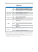
Chapter 1 Get to Know About Your Modem Router LED Explanation Name Internet Wireless 2.4Ghz Wireless 5Ghz LAN WPS USB Status Indication On The network is available with a successful Internet connection. Off There is no successful Internet connection or the modem router is operating in Bridge mode. Please refer to Note 2 for troubleshooting. On The wireless 2.4GHz band is working properly. Off The wireless 2.4 GHz band is disabled. On The wireless 5GHz band is working properly.
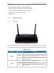
Chapter 1 1. 3. 2. Get to Know About Your Modem Router The Back Panel The modem router’s back panel shows the connection ports, buttons and antennas. Refer to the following for detailed instructions. Item Description ADSL For connecting the modem router to the Internet. Connect the port to the splitter or directly connect the port to the phone jack via a phone cable. For details, please refer to Connect the Modem Router. USB For connecting to a USB storage device or a USB printer.
Chapter 2 Connect the Hardware This chapter contains the following sections: • Position Your Modem Router • Connect Your Modem Router
Chapter 2 2. 1. Connect the Hardware Position Your Modem Router With the modem router, you can access your network from anywhere within the wireless network coverage. However, the wireless signal strength and coverage varies depending on the actual environment where your modem router is in. Many obstacles may limit the range of the wireless signal, for example, concrete structures, thickness and number of walls.
Chapter 2 Connect the Hardware Power Adapter 3 Turn on the modem router. Modem Router Phone Jack 1 Connect the ADSL splitter to the phone jack. 2 Connect the modem router to the ADSL splitter. ADSL Splitter Connect to the phone (Optional) 2. Connect your computer to the modem router. Method 1: Wired Connect your computer’s Ethernet port to the LAN port on the modem router Archer D20 via the Ethernet cable.
Chapter 2 Connect the Hardware 3 ) The WPS LED flashes for about two minutes during the WPS process. 4 ) When the WPS LED is on, the client device has successfully connected to the modem router.
Chapter 3 Log into Your Modem Router
Chapter 3 Log into Your Modem Router With a Web-based utility, it is easy to configure and manage the Archer D20 AC750 Wireless Dual Band ADSL2+ Modem Router. The Web-based utility can be used on any Windows, Macintosh or UNIX OS with a Web browser, such as Microsoft Internet Explorer, Mozilla Firefox or Apple Safari. Follow the steps below to log into your modem router. 1.
Chapter 4 Set Up Internet Connections This chapter introduces how to connect your modem router to the Internet. The modem router is equipped with a web-based Quick Setup wizard. It has many ISP information built in, automates many of the steps and verifies that those steps have been successfully completed. Furthermore, you can also set up an IPv6 connection if your ISP provided IPv6 service.
Chapter 4 4. 1. Set Up Internet Connections Use Quick Setup Wizard To set up your modem router with several easy steps quickly: 1. Visit http://tplinkmodem.net, and log in with the password you set for the modem router. 2. Click Quick Setup, select your ISP from the dropdown list or select Other if you can’t find your ISP, then click Next. 3. Follow the on-screen instructions to complete the setup. Note: 1.
Chapter 4 Set Up Internet Connections 3. Click Save to make the settings effective and you can refer to Test Internet Connectivity to test the Internet connection. Tips: You can view and edit all Internet connections on Advanced > Network > Internet page. 4. 3. Set up an IPv6 Connection If the DSL line your ISP provided also supports IPv6 connection and your ISP has provided some detailed IPv6 parameters, you can configure the modem router to permit IPv6 connection.
Chapter 4 Set Up Internet Connections Select the checkbox to enable IPv6 feature. Addressing Type: Consult your ISP for the addressing type, DHCPv6 or SLAAC. SLAAC is the most commonly used addressing type. IPv6 Gateway: Keep the default setting as Current Connection. Note: If your ISP has provided the IPv6 address, click Advanced to reveal more settings. Check to use IPv6 specified by ISP and enter the parameters provided by your ISP. 4 ) Click OK to make the settings effective. 2.
Chapter 4 4. 4. Set Up Internet Connections Test Internet Connectivity After manually setUJOH up the Internet connection, you need to know the Internet connectivity. The modem router provides a diagnostic tool to help you locate the malfunction. 1. Visit http://tplinkmodem.net, and log in with the password you set for the modem router. 2. Go to Advanced > System Tools > Diagnostics page. 3. Click Start to test the Internet connectivity and you will see the test result in the gray box.
Chapter 5 Bandwidth Control The Bandwidth Control feature is used to fully utilize your limited bandwidth and optimize the load respectively. With this feature enabled, you can assign a specific minimum or maximum bandwidth for each computer, thus minimizing the impact caused when the connection is under heavy load.
Chapter 5 I want to: Bandwidth Control Use an independent bandwidth and enjoy a good Internet experience without being affected by other users who are sharing the same router. For example, my roommate and I share 512Kbps Upstream Bandwidth and 8Mbps Downstream Bandwidth via this router, she likes to watch live show and play online games, which may take up much bandwidth. I don’t want to be affected, so we agree to equally distribute the bandwidth. Our IP addresses are 192.168.1.101 and 192.168.1.110.
Chapter 5 Bandwidth Control 1 ) IP Range: Enter the IP address. The field can be single IP address or IP address range according to your demands. When you configure the single IP address, the computer with this IP address will get independent given bandwidth. When you configure the IP address range, all computers in the range will share the given bandwidth. 2 ) Port Range: Keep the default settings. The default port range of TCP protocol or UDP protocol is from 1 to 65535.
Chapter 5 Done! Bandwidth Control Now you and your roommate have an independent bandwidth.
Chapter 6 Network Security This chapter guides you on how to protect your home network from unauthorized users by implementing these three network security functions. You can block or allow specific client devices to access your wireless network using MAC Filtering, or using Access Control for wired and wireless networks, or you can prevent ARP spoofing and ARP attacks using IP & MAC Binding.
Chapter 6 6. 1. Network Security MAC Filtering This function exploits the uniqueness of the MAC (Medium Access Control) address, a unique 12-digit hexadecimal address (for example, D8:5D:4C:B4:46:EA) of every network device, to determine if the device can or cannot access your wireless network. I want to: Prevent unauthorized users from accessing my wireless network by utilizing the network device’s MAC address and IP address. For example, I have a computer that is connected to my wireless network.
Chapter 6 Network Security To block specific device(s) 1 ) Select Block wireless access from the devices in the list below and click Save. 2 ) Select the device(s) to be blocked in the Devices Online table. 3 ) Click Block above the Devices Online table. The selected devices will be added to Devices List automatically. To allow specific device(s) 1 ) Select Allow wireless access only from the devices in the list below and click Save. 2 ) Click Add.
Chapter 6 How can I do that? Network Security 1. Visit http://tplinkmodem.net, and log in with the password you set for the router. 2. Go to Advanced > Security > Access Control and enable Access Control. 3. Select the access mode to either block (recommended) or allow the device(s) in the list. To block specific device(s) 1 ) Select Blacklist and click Save. 2 ) Select the device(s) to be blocked in the Devices Online table. 3 ) Click Block above the Devices Online table.
Chapter 6 Network Security 3 ) Enter the Device Name and MAC Address (You can copy and paste the information from Devices Online table if the device is connected to your network). 4 ) Click OK. Now you can block or allow specific client devices to access your network (via wired or wireless) using the Blacklist or Whitelist. Done! 6. 3. IP & MAC Binding IP & MAC Binding, namely, ARP (Address Resolution Protocol) Binding, is used to bind network device’s IP address to its MAC address.
Chapter 6 Network Security 3. Bind your device(s) according to your needs. To bind the connected device(s) 1 ) Select the device(s) to be bound in the ARP List. 2 ) Click Bind to add to the Binding List. To bind the unconnected device 1 ) Click Add. 2 ) Enter the MAC address and IP address that you want to bind. 3 ) Select the checkbox to enable the entry and click OK. Done! Now you don’t need to worry about ARP spoofing and ARP attacks.
Chapter 7 IPTV IPTV is the abbreviation of Internet Protocol Television. The service can only be delivered through the Internet, and our modem router provides a specific LAN port for IPTV. By automatically seperating IPTV from Internet surfing, we guarantee you a high quality of vJdFo streaming and a high speed of Internet surfing.
Chapter 7 I want to: IPTV Configure the modem router to enable Internet Protocol Television (IPTV) Services. For example, I already bought IPTV service, but this service can only be delivered through the Internet. Therefore, I need to configure my modem router first. How can I do that? 1. Visit http://tplinkmodem.net, and log in with the password you set for the router. 2. Go to Advanced > IPTV to open the configuration page. 3. Click Enable IPTV to enable this function. 4.
Chapter 8 USB Application This chapter describes how to share and access USB devices connected to the modem router among different clients. The modem router only supports USB external flash drives, hard drives and USB printers, and does not support USB 3G/4G modems.
Chapter 8 8. 1. USB Application Local Storage Sharing Share your USB storage devices with different users on the network. 8. 1. 1. Access the USB disk 1. Connect Your USB Disk Insert your USB storage device into the modem router’s USB port directly or using a USB cable. Wait several seconds until the USB LED becomes solid on. Tips: • If you use USB hubs, make sure no more than 4 devices are connected to the modem router.
Chapter 8 USB Application 2. Select Basic > USB Settings > Sharing Access. Focus on the Folder Sharing section. Click the button to disable Share All, then click Add to add a new sharing folder. 3. Select the Volume Name and Folder Path, then enter a Folder Name as you like. 4. Decide the way you share the folder: • Enable Authentication: Tick to enable authentication for this folder sharing, and you will be required to use a username and password to access the USB disk.
Chapter 8 USB Application 2. Select Advanced > USB Settings > Sharing Access. 3. Choose to use the default Account (admin) or use a new account and click Save. 4. Enable Authentication to apply the account you just set. • If you leave Share All enabled, click the button to enable Authentication for all folders. • If Share All is disabled, enable Authentication for specific folders. ¾ To Customize the Address of the USB Disk You can customize the server name and use the name to access your USB disk.
Chapter 8 USB Application 4. Now you can access the USB disk with \\MyShare (smb://MyShare for Mac). 8. 2. Remote Access via FTP Server You can access your USB disk outside the local area network. For example: • Share photos and other large files with your friends without logging in to (and paying for) a photo-sharing site or email system. • Get a safe backup for the materials for a presentation. • Remove the files on your camera’s memory card from time to time during the journey.
Chapter 8 USB Application It is strongly recommended that you set and apply a sharing account for data security. 1 ) Visit http://tplinkmodem.net, then log in with the password you set for the modem router. 2 ) Select Advanced > USB Settings > Sharing Access. 3 ) Choose to use the default Account (admin) or use a new account and click Save. 4 ) Enable Authentication to apply the sharing account. • If you leave Share All enabled, click the button to enable Authentication for all folders.
Chapter 8 USB Application 4. Access Your USB Disk via Internet Now different clients with Internet connection can access the USB disk: Computer Pad • To download, open a web browser and type the server address ftp://: (such as ftp://59.40.2.243:21) or ftp://: (such as ftp:// MyDomainName:21) in the address bar, then press Enter on the keyboard. • To upload, use a third-party app for network files management.
Chapter 8 USB Application 3. Select the Volume Name and Folder Path, then specify the Folder Name as you like. 4. Tick Enable Authentication. If you allow network clients to modify this folder, tick Enable Write Access. 5. Click OK. Tips: The modem router can share eight volumes at most. You can click volume you do not need to share. 8. 3.
Chapter 8 USB Application • Before you physically disconnect a USB device from the modem router, safely remove it to avoid data damage: Go to Advanced > USB Settings > Device Settings and click . 2. Access the Media Files on Your USB Disk Now the DLNA-supported devices (such as your computer and pad) connected to the modem router can detect and play the media files on the USB disks. 1. Open the Windows Media Player. 2.
Chapter 8 USB Application 4. Select the Volume Name and Folder Path, then enter a Folder Name as you like. 5. Tick Enable Media Sharing and click OK. Tips: The modem router can share eight volumes at most. You can click volume you do not need to share. on the page to detach the corresponding ¾ To Specify the Media Server You can also modify the media server name or disable the feature of Media Sharing as needed. 1. Visit http://tplinkmodem.net, then log in with the password you set for the modem router.
Chapter 8 8. 4. USB Application Printer Sharing The feature of Printer Sharing helps you share a printer with different computers connected to the modem router. Note: Printers unlisted on this page may be incompatible with the modem router: http://www.tp-link.com/common/ compatible/print-server/. 1. Install the Driver of the Printer Make sure you have installed the driver of the printer on each computer that needs printer service. If you do not have the driver, contact the printer manufacturer. 2.
Chapter 8 USB Application Windows Mac 3 ) Click the Auto-Connect for printing tab to pull down a list, then select Set AutoConnect Printer. Windows Mac 4 ) Select the printer you share, then click Apply.
Chapter 8 USB Application Windows Mac 5 ) You will see the printer marked as Auto-Connect Printer. Now you can print with this printer.
Chapter 8 USB Application Windows Mac Tips: The Print Server also allows different clients to share the scan feature of MFPs (Multi-Function Printers). To scan with TP-LINK USB Printer Controller, right-click the printer and select Network Scanner. Then, a scanning window will pop up. Finish the scanning process by following on-screen instructions.
Chapter 9 Parental Controls This function allows you to block inappropriate, explicit and malicious websites, and control access to specified websites at specified time.
Chapter 9 I want to: Parental Controls control what types of websites my children or other home network users can visit and even the time of day they are allowed to access the Internet. For example, I want to allow my children’s devices (e.g. a computer or a tablet) to access only www.tp-link.com and Wikipedia.org from 18:00 (6PM) to 22:00 (10PM) on weekdays and not other time. How can I do that? 1. Visit http://tplinkmodem.net, and log in with the password you set for the router. 2.
Chapter 9 Parental Controls 4. Click View Existing Devices, and select the device to be controlled. Or, enter the Device Name and MAC Address manually. icon to set the Internet Access Time. Drag the 5. Click the cursor over the appropriate cell(s) and click OK. 6. Enter a Description for the entry. 7. Select the checkbox to enable this entry and click OK. 8. Select the restriction mode.
Chapter 9 Parental Controls 9. Click Add a New Keyword. You can add up to 200 keywords for both Blacklist and Whitelist. Below are some sample entries to allow access. 1 ) Enter a web address (e.g. www.tp-link.com) or a web address keyword (e.g. wikipedia) to only allow or block access to the websites containing that keyword. 2 ) Specify the domain suffix (eg. .edu or .org) to allow access only to the websites with that suffix.
Chapter 10 Guest Network This function allows you to provide Wi-Fi access for guests without disclosing your main network. When you have guests in your house, apartment, or workplace, you can create a guest network for them. In addition, you can assign network authorities and bandwidth for guests to ensure network security, privacy, and fluency.
Chapter 10 Guest Network 10. 1. Create a Network for Guests 1. Visit http://tplinkmodem.net, and log in with the password you set for the modem router. 2. Go to Advanced > Guest Network. Locate the Wireless Settings section. 3. Create a 2.4GHz or 5GHz guest network according to your needs. 1 ) Enable Wireless Network 2.4GHz or Wireless Network 5GHz. 2 ) Set an easy-to-identify SSID. Don‘t select Hide SSID unless you want your guests and other people to manually input this SSID for Wi-Fi access.
Chapter 10 Guest Network 3. Assign network authorities and bandwidth according to your needs. • Allow guests to see each other Select this checkbox to allow the clients in your guest network to access each other. • Allow guests to access my local network Select this checkbox to allow the clients in your guest network to access your local network, not just Internet access.
Chapter 11 NAT Forwarding Modem router’s NAT (Network Address Translation) feature makes the devices in the LAN use the same public IP address to communicate in the Internet, which protects the local network by hiding IP addresses of the devices. However, it also brings about the problem that external host cannot initiatively communicate with the specified device in the local network.
Chapter 11 NAT Forwarding 11. 1. Share Local Resources in the Internet by Virtual Server When you build up a server in the local network and want to share it on the Internet, Virtual Server can realize the service and provide it to the Internet users. At the same time virtual server can keep the local network safe as other services are still invisible from the Internet. Virtual server can be used for setting up public services in your local network, such as HTTP, FTP, DNS, POP3/SMTP and Telnet.
Chapter 11 NAT Forwarding 4. Click View Existing Services, and choose HTTP. The external port, internal port and protocol will be automatically filled with contents. Enter the PC’s IP address 192.168.0.100 in the Internal IP field. 5. Click OK to save the settings. Tips: 1. It is recommended to keep the default settings of Internal Port and Protocol if you are not clear about which port and protocol to use. 2.
Chapter 11 NAT Forwarding modem router can forward them to the corresponding host. Port triggering is mainly applied to online games, VoIPs and video players. Common applications include MSN Gaming Zone, Dialpad and Quick Time 4 players, etc. Follow the steps below to configure the port triggering rules: 1. Visit http://tplinkmodem.net, and log in with the password you set for the modem router. 2. Go to Advanced > NAT Forwarding > Port Triggering and click Add. 3.
Chapter 11 NAT Forwarding all ports opened. When you are not clear about which ports to open in some special applications, like IP camera and database software, you can set the PC to be a DMZ host. Note: DMZ is more applicable in the situation that users are not clear about which ports to open. When it is enabled, the DMZ host is totally exposed to the Internet, which may bring some potential safety hazard. If DMZ is not in use, please disable it in time.
Chapter 11 NAT Forwarding to use applications for multiplayer gaming, peer-to-peer connections, real-time communication (such as VoIP or telephone conference) or remote assistance, etc. Tips: 1. UPnP is enabled by default in this modem router. 2. Only the application supporting UPnP protocol can use this feature. 3. UPnP feature needs the support of operating system (e.g. Windows Vista/ Windows 7/ Windows 8, etc. Some of operating system need to install the UPnP components).
Chapter 12 Specify Your Network Settings This chapter introduces how to change the default settings or adjust the basic configuration of the modem router using the web-based management page.
Chapter 12 Specify Your Network Settings 12. 1. LAN Settings 12. 1. 1. Change the LAN IP Address The modem router is preset with a default LAN IP 192.168.1.1, which you can use to log in to its web-based management page. The LAN IP address together with the Subnet Mask also defines the subnet that the connected devices are on. If the IP address conflicts with another device on your local network or your network requires a specific IP subnet, you can change it.
Chapter 12 Specify Your Network Settings Follow the steps below to configure DHCP server. 1. Visit http://tplinkmodem.net, and log in with the password you set for the modem router. 2. Go to Advanced > Network > LAN Settings page and select IPv4. 3. Select DHCP to enable the DHCP function and select DHCP Server. 4. Specify the IP Address Pool, the start address and end address must be on the same subnet with LAN IP. The modem router will assign addresses within this specified range to its clients.
Chapter 12 Specify Your Network Settings permanent IP addresses, please configure Address Reservation on the router for the purpose. Follow the steps below to reserve an IP address for your device. 1. Visit http://tplinkmodem.net, and log in with the password you set for the modem router. 2. Go to Advanced > Network > LAN Settings page and select IPv4. 3. Scroll down to locate the Address Reservation table and click Add to add an address reservation entry for your device. 4.
Chapter 12 Specify Your Network Settings ¾ To enable or disable the wireless function: Enable the Wireless Network 2.4GHz or 5GHz. If you don’t want to use the wireless function, just uncheck the box. If you disable the wireless function, all the wireless settings won’t be effective. ¾ To change the wireless network name (SSID) and wireless password: Enter a new SSID using up to 32 characters. The default SSID is TP-LINK_XXXX and the value is case-sensitive.
Chapter 12 Specify Your Network Settings • 802.11ac/n mixed (5Ghz): Select if you are using both 802.11ac and 802.11n wireless clients. • 802.11a/n/ac mixed (5Ghz): Select if you are using a mix of 802.11a, 802.11n and 802.11ac wireless clients. It is strongly recommended that you select 11a/n/ac mixed. Channel: Select the channel you want to use from the drop-down list. This field determines which operating frequency will be used.
Chapter 12 Specify Your Network Settings Method 2 Enter the client device’s PIN on the modem router 1. Visit http://tplinkmodem.net, and log in with the password you set for the modem router. 2. Go to Advanced > Wireless >WPS page. Select the wireless network 2.4GHz or 5GHz according to your wireless client. 3. Keep the default WPS status as Enabled and select the PIN Code radio button. 4. Enter the client device’s PIN in the field on the above WPS screen. Then click the Connect button. 5.
Chapter 12 Specify Your Network Settings 3. Keep the Router’s PIN status as enabled. Take a note of the Current PIN of the modem router. You can also click the Generate button to get a new PIN. 4. On the client device, enter the modem router’s PIN. (The default PIN is also labeled on the bottom of the modem router.) 5. The WPS LED flashes for about two minutes during the WPS process. 6. When the WPS LED is on, the client device has successfully connected to the modem router. Note: 1.
Chapter 12 Specify Your Network Settings 4. Set the time. Drag the cursor to cover the time area and click Save to make the settings effective. The selected time will be in green. 5. Repeat steps 3 and 4 to set time for 5GHz wireless network. Note: 1. If you just set time for one wireless band, the other wireless band is still always on, so set time for both of the two bands to schedule your whole wireless network. 2. The wireless LED (2.
Chapter 12 Specify Your Network Settings Tips: You can also see the wrieless details by clicking the router icon on Basic> Network Map. ¾ To view the detailed information of the connected wireless clients: 1. Visit http://tplinkmodem.net, and log in with the password you set for the modem router. 2. Go to Advanced > Wireless > Statistics page. 3. You can view the detailed information of the wireless clients, including its connected wireless band and security option as well as the packets transmitted.
Chapter 12 Specify Your Network Settings • Beacon Interval: Enter a value between 25 and 1000 in milliseconds to determine the duration between which beacon packets are broadcasted by the router to synchronize the wireless network. The default is 100 milliseconds. • RTS Threshold: Enter a value between 1 and 2346 to determine the packet size of data transmission through the router. By default, the RTS (Request to Send) Threshold size is 2346.
Chapter 12 Specify Your Network Settings 12. 3. Set Up a Dynamic DNS Service Account Most ISPs (Internet service providers) assign a dynamic IP address to the router and you can use this IP address to access your router remotely. However, the IP address can change any time and you don’t know when it changes. In this case, you might need the DDNS (Dynamic Domain Name Server) feature on the router to allow you and your friends to access your router and local servers (FTP, HTTP, etc.
Chapter 12 How can I do that? Specify Your Network Settings 1. Visit http://tplinkmodem.net, and log in with the password you set for the modem router. 2. Go to Advanced > Network > Interface Grouping to open the configuration page where some interfaces can be grouped together. 3. Click to Add a new group. 4. Name the group. 5. Check the boxes of LAN1 and LAN3 in Available LAN. Here Wi-Fi 2.4G network and Wi-Fi 5G network are viewed as a LAN interface respectively. 6.
Chapter 12 Done! Specify Your Network Settings Now your working devices connected to LAN1 and LAN3 are in an isolated group! Note: VLAN function is enabled by default. You cannot disable it when IPTV is enabled. 12. 5. Create Static Routes A static route is a pre-determined path that network information must travel to reach a specific host or network. Data from one point to another will always follow the same path regardless of other considerations.
Chapter 12 Specify Your Network Settings 4. Click Add to add a new static routing entry. Finish the settings according to the following explanations: • Destination IP: The destination IP address that you want to assign to a static route. This IP address cannot be on the same subnet with the WAN IP or LAN IP of the router. In the example, the IP address of the company network is the destination IP address, so here enters 172.30.30.1.
Chapter 12 Specify Your Network Settings Router 2 and then to the Server, so the default gateway should be 192.168.0.2. • Interface: Determined by the port (WAN/LAN) that sends out the data packets. In the example, the data is sent to the gateway through the LAN port, so LAN should be selected. 5. Check to enable this entry and click OK to save the settings. Done! Open a web browser on your PC. Enter the company server’s IP address to visit the company network. 12. 6.
Chapter 12 Specify Your Network Settings Site A Modem Router 2 WAN: 219.134.112.246 Site B WAN: 219.134.112.247 Modem router 1 LAN: 192.168.1.1 Subnetmask: 255.255.255.0 LAN: 192.168.2.1 Subnetmask: 255.255.255.0 PC 1 How can I do that? PC 2 1. Make sure of the topology you want to build and record site A (local network) and site B (remote network)’s LAN IP and WAN IP. 2. Configuration on site A (local network). 1 ) Visit http://tplinkmodem.
Chapter 12 Specify Your Network Settings 3 ) In the IPSec Connection Name column, specify a name. 4 ) In the Remote IPSec Gateway (URL) column, Enter Site B’s WAN IP address. 5 ) To configure Site A’s LAN: In the Tunnel access from local IP addresses column, here we take Subnet Address as an example. Then input the LAN IP range of Site A in the IP Address for VPN column, and input Subnet Mask of Site A.
Chapter 12 Specify Your Network Settings 8 ) Enter the Pre-Shared Key for IKE authentication. Then keep Perfect Forward Secrecy enabled. Note: The key should consist of visible characters without blank space. Make sure Site A and Site B use the same key. 9 ) Leave the Advanced Settings as default value. Then click OK to save. 3. Configuration on Site B (remote network).
Chapter 12 Specify Your Network Settings If Ping proceeds successfully (gets replies from host in Site B), the IPSec connection is working properly now. Done! Now IPSec VPN is implemented to establish a connection. Note: 1. The product supports a maximum of ten simultaneous connections. 2.
Chapter 13 Administrate Your Network This chapter introduces how to change the system settings and administrate your modem router’s network.
Chapter 13 Administrate Your Network 13. 1. Set System Time System time is the time displayed while the modem router is running. The system time you configure here will be used for other time-based functions like Parental Controls and Wireless Schedule. You can manually set how to get the system time. Follow the steps below to set your system time. 1. Visit http://tplinkmodem.net, and log in with the password you set for the modem router. 2. Go to Advanced > System Tools > Time Settings page. 3.
Chapter 13 Administrate Your Network 13. 2. Update the Firmware TP-LINK is dedicated to improving and enriching the product features, giving you a better network experience. We will release the latest firmware at TP-LINK official website, you can download the latest firmware file from our website: www.tp-link.com and upgrade the firmware to the latest version. Follow the steps below to update your firmware to the latest. 1. Download the latest firmware file from our website: www.tp-link.com. 2.
Chapter 13 Administrate Your Network 13. 3. Back up and Restore Configuration Settings The configuration settings are stored as a configuration file in the router. You can back up the configuration file to your computer for future use and restore the modem router to a previous settings from the backup file when needed. Moreover, if needed you can erase the current settings and reset the modem router to the default factory settings. To back up configuration settings: 1. Visit http://tplinkmodem.
Chapter 13 Administrate Your Network 13. 4. Change the Administrator Account Admin account is used to log in to the modem router’s web-based management page. You are required to set the admin account at first login. You can also change it on the web page. 1. Visit http://tplinkmodem.net, and log in with the password you set for the modem router. 2. Go to Advanced > System Tools> Administration page. Locate the Account Management section. 3. Enter the old password.
Chapter 13 Administrate Your Network 4. Click Save to make the settings effective. Now only the device (192.168.1.100) can manage the modem router. If you want that all local devices can manage the modem router, just leave the IP/MAC Address field blank. 13. 6. Remote Management By default, the remote devices are not allowed to manage the modem router from the Internet. Follow the steps below to allow remote devices to manage the modem router. 1. Visit http://tplinkmodem.
Chapter 13 Administrate Your Network 13. 7. System Log System Log can help you know what happened to your modem router, facilitating you to locate the malfunctions. For example when your modem router does not work properly, you will need to save the system log and send it to the technical support for troubleshooting. 1. Visit http://tplinkmodem.net, and log in with the password you set for the modem router. 2. Click Advanced > System Tools > System Log page. To view the system logs: 1.
Chapter 13 Administrate Your Network Click Save Log to save the logs in a txt file to your computer. Click Log Settings to set the save path of the logs. • Save Locally: Select this option to cache the system log to the router’s local memory, select the minimum level of system log to be saved from the drop-down list. The logs will be shown in the table in descending order on the System Log page.
Chapter 13 Administrate Your Network 13. 9. CWMP Settings The modem router offers CWMP feature. The function supports TR-069 protocol which collects information, diagnoses the devices and configures the devices automatically via ACS (Auto-Configuration Server). 1. Visit http://tplinkmodem.net, and log in with the password you set for the modem router. 2. Go to Advanced > System Tools > CWMP Settings page.
Chapter 13 Administrate Your Network • Enable CWMP: Toggle On to enable the CWMP (CPE WAN Management Protocol) feature. • Inform: Enable this feature to send an Inform message to the ACS (Auto Configuration Server) periodically. • Inform Interval: Enter the time interval in seconds when the Inform message will be sent to the ACS. • ACS URL: Enter the web address of the ACS which is provided by your ISP. • ACS Username/Password: Enter the username/password to log in to the ACS server.
Chapter 13 Administrate Your Network • Connection Request Port: Enter the port that connects to the ACS server. • Connection Request URL: Enter the URL that connects to the ACS server. • Get RPC methods: Click to get the methods to support CWMP. Click Save to make the settings effective. 13. 10. SNMP Settings SNMP (Simple Network Management Protocol) has been widely applied in the computer networks currently, which is used for ensuring the transmission of the management information between two nodes.
Chapter 13 Administrate Your Network messages, sending responses to the SNMP manager, and triggering SNMP traps when an event occurs. • Read-only Community: Displays the default public community string that protects the router from unauthorized access. • Set Community: Displays the default read and write community string that protects the router from unauthorized changes. • System Name: Displays the administratively-assigned name for this managed device.
Appendix A: Specifications General Standards and Protocols Safety & Emission Ports Network Medium Data Rates System Requirement ANSI T1.413, ITU G.992.1, ITU G.992.3, ITU G.992.5, IEEE 802.11a, IEEE 802.11b, IEEE 802.11g, IEEE 802.11n, IEEE 802.11ac, IEEE 802.3, IEEE 802.3u, TCP/IP, PPPoA, PPPoE, SNTP, HTTP, DHCP, ICMP, NAT FCC, CE Four 10/100M Auto-Negotiation RJ45 ports (Auto MDI/MDIX) One RJ11 port One USB 2.
Appendix B: Troubleshooting T1. How do I restore my modem router’s configuration to its factory default settings? With the modem router powered on, press and hold down the WPS/RESET button on the rear panel of the modem router for 8 seconds until all LEDs turn back on momentarily, then release the button. Note: Once the modem router is reset, the current configuration settings will be lost and you will need to reconfigure the modem router. T2.
4 ) Click LAN settings, deselect the following three options and click OK; 5 ) Go to Advanced > Restore advanced settings, click OK to save the settings.
• Change a web browser or computer and log in again. • Reset the modem router to factory default settings: With the modem router powered on, press and hold down the WPS/RESET button on the rear panel of the modem router for 8 seconds until all LEDs turn back on momentarily, then release the button. Note: You’ll need to reconfigure the modem router to surf the Internet once the modem router is reset. Open a web browser and log in again. If login fails, please contact the technical support. T4.
4. Refer to T5 to clone the MAC address. 5. If you still cannot access the Internet, please restore your modem router to its factory default settings and reconfigure your modem router by following the instructions in Use Quick Setup Wizard. 6. Please contact our Technical Support if the problem still exists. T5. How to configure MAC Clone? You can manually change the MAC address of the modem router.
2. Visit http://tplinkmodem.net, and log in with password you set for the modem router. 3. Go to Advanced > Operation Mode page. 4. Select the Wireless Router Mode option and click Save to make the settings effective. Note: IPTV function is not supported in Wireless Router Mode. T7. How to use the WDS Bridging function to extend my wireless network? My house covers a large area. The wireless network coverage of the router I’m using (the root router) is limited.
5. Click the connect icon and then the SSID and MAC will be automatically filled in. Configure the Security settings as the AP you choose to be bridged. 6. Click Save to make the settings effective. 7. Go to Advanced > Network > LAN Settings page to disable DHCP. Now, the root’s wireless network is extended and you can use the modem router’s SSID and password to enjoy the network.
2. Make sure the wireless adapter driver is installed successfully and the wireless adapter is enabled. On Windows 7 1 ) If you see the message No connections are available, it is usually because the wireless function is disabled or blocked somehow; 2 ) Clicking on Troubleshoot and windows might be able to fix the problem by itself.
5 ) Select Wireless Zero Configuration, right click, and then select Properties; 6 ) Change Startup type to Automatic, click on Start button and make sure the Service status is Started. And then click OK.
7 ) Connect to wireless network. ¾ If you can find other wireless network except your own, please follow the steps below: 1. Check the WLAN LED indicator on your wireless router/modem; 2. Make sure your computer/device is still in the range of your router/modem, move closer if it is currently too far away; 3.
Password/Network Security Key, usually you can only find it on the back of your wireless router/modem; 2 ) If you cannot find the PIN or PIN failed, you may choose “Connecting using a security key instead”, and then type in the Network Security Key/Wireless Password; 3 ) If it continues on saying network security key mismatch, it is suggested to confirm the wireless password on your wireless router/modem; Note: Wireless password/Network Security Key is case sensitive. 4 ) Connect to wireless network.
2. Windows was unable to connect to XXXX /Cannot join this network/Taking longer than usual to connect to this network. 1 ) Check the wireless signal strength of your network, if it is weak (1~3 bars), please move the router closer and try again; 2 ) Change the wireless Channel of the router to 1,6,or 11 to reduce interference from other networks; 3 ) Re-install or update the driver for your wireless adapter of the computer; 4 ) Connect to wireless network.
COPYRIGHT & TRADEMARKS Specifications are subject to change without notice. is a registered trademark of TP-LINK TECHNOLOGIES CO., LTD. Other brands and product names are trademarks or registered trademarks of their respective holders. No part of the specifications may be reproduced in any form or by any means or used to make any derivative such as translation, transformation, or adaptation without permission from TP-LINK TECHNOLOGIES CO., LTD. Copyright © 2015 TP-LINK TECHNOLOGIES CO., LTD.
FCC STATEMENT This equipment has been tested and found to comply with the limits for a Class B digital device, pursuant to part 15 of the FCC Rules. These limits are designed to provide reasonable protection against harmful interference in a residential installation. This equipment generates, uses and can radiate radio frequency energy and, if not installed and used in accordance with the instructions, may cause harmful interference to radio communications.
CE Mark Warning This is a class B product. In a domestic environment, this product may cause radio interference, in which case the user may be required to take adequate measures. ATTENTION: Due to EU law, the country settings must be identical to the country where the device is operating (important due to non-harmonised frequencies in the EU). Restricted to indoor use.
To reduce potential radio interference to other users, the antenna type and its gain should be so chosen that the equivalent isotropically radiated power (e.i.r.p.) is not more than that permitted for successful communication. Industry Canada Statement Complies with the Canadian ICES-003 Class B specifications. Cet appareil numérique de la classe B est conforme à la norme NMB-003 du Canada. This device complies with RSS 210 of Industry Canada.
Продукт сертифіковано згідно с правилами системи УкрСЕПРО на відповідність вимогам нормативних документів та вимогам, що передбачені чинними законодавчими актами України. Safety Information • When product has power button, the power button is one of the way to shut off the product; when there is no power button, the only way to completely shut off power is to disconnect the product or the power adapter from the power source. • Don’t disassemble the product, or make repairs yourself.
TP-LINK TECHNOLOGIES CO., LTD DECLARATION OF CONFORMITY For the following equipment: Product Description: AC750 Wireless Dual Band ADSL2+ Modem Router Model No.