User Guide For TP-LINK Auranet Access Points EAP115 REV1.0.
FCC STATEMENT This equipment has been tested and found to comply with the limits for a Class A digital device, pursuant to part 15 of the FCC Rules. These limits are designed to provide reasonable protection against harmful interference when the equipment is operated in a commercial environment. This equipment generates, uses, and can radiate radio frequency energy and, if not installed and used in accordance with the instruction manual, may cause harmful interference to radio communications.
IC STATEMENT This Class A digital apparatus complies with Canadian ICES-003. Cet appareil numérique de la classe A est conforme à la norme NMB-003 du Canada. Canadian Compliance Statement This device complies with Industry Canada license-exempt RSSs. Operation is subject to the following two conditions: 1) This device may not cause interference, and 2) This device must accept any interference, including interference that may cause undesired operation of the device.
Продукт сертифіковано згідно с правилами системи УкрСЕПРО на відповідність вимогам нормативних документів та вимогам, що передбачені чинними законодавчими актами України. Safety Information When product has power button, the power button is one of the way to shut off the product; When there is no power button, the only way to completely shut off power is to disconnect the product or the power adapter from the power source. Don’t disassemble the product, or make repairs yourself.
第十四條 低功率射頻電機之使用不得影響飛航安全及干擾合法通行;經發現有干擾現象時, 應立即停用,並改善至無干擾時方得繼續使用。前項合法通信,指依電信規定作業之無線電 信。低功率射頻電機需忍受合法通信或工業、科學以及醫療用電波輻射性電機設備之干擾。 減少電磁波影響,請妥適使用。 安全諮詢及注意事項 ●請使用原裝電源供應器或只能按照本產品注明的電源類型使用本產品。 ●清潔本產品之前請先拔掉電源線。請勿使用液體、噴霧清潔劑或濕布進行清潔。 ●注意防潮,請勿將水或其他液體潑灑到本產品上。 ●插槽與開口供通風使用,以確保本產品的操作可靠並防止過熱,請勿堵塞或覆蓋開口。 ●請勿將本產品置放於靠近熱源的地方。除非有正常的通風,否則不可放在密閉位置中。 ●請不要私自打開機殼,不要嘗試自行維修本產品,請由授權的專業人士進行此項工作。 此為甲類資訊技術設備,于居住環境中使用時,可能會造成射頻擾動,在此種情況下,使用 者會被要求採取某些適當的對策。
CONTENTS Chapter 1 About This Guide ............................................................................................................................. 1 1.1 Intended Readers ................................................................................................................................. 1 1.2 Conventions ........................................................................................................................................... 1 Chapter 2 Introduction .......
6.3.6 6.4 Rogue AP Detection ............................................................................................................... 44 Monitoring........................................................................................................................................... 48 6.4.1 AP .................................................................................................................................................. 48 6.4.2 SSID.........................................
7.5 7.4.2 Web Server ............................................................................................................................... 109 7.4.3 Management Access ............................................................................................................ 110 7.4.4 LED ON/OFF............................................................................................................................. 111 7.4.5 SSH ..........................................................
Chapter 1 About This Guide This User Guide contains information for setup and management of EAP115. Please read this guide carefully before operation. 1.1 Intended Readers This Guide is intended for network managers familiar with IT concepts and network terminologies. 1.2 Conventions When using this guide, please notice that features of the EAP may vary slightly depending on the model and software version you have, and on your location, language, and Internet service provider.
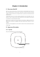
Chapter 2 Introduction 2.1 Overview of the EAP EAP series products provide wireless coverage solutions for small-medium business. They can either work independently as standalone APs or implement centralized management, providing a flexible, richly-functional but easily-configured enterprise-grade wireless network for small and medium business. “Celling lamp” appearance and easily mounting design with chassis make EAP easy to be installed on a wall or ceiling and blend in with most interior decorations.
LED There is a System LED on the top of the EAP. The following table explains the indications of different LED colors. LED Color Indication Flashing green System initialization is complete. Solid green The device is working properly. Flashing red System errors. RAM, flash, Ethernet, WLAN or firmware may be malfunctioning. Flashing yellow Firmware update is in progress. Do not disconnect or power off the device. Alternating red/green/yellow twice The device is being reset. 2.2.
2.2.3 Mounting Bracket The following figure describes the structure of the mounting bracket.
Chapter 3 Typical Topology A typical topology for the EAP is described below. Figure 3-1 Typical Topology To deploy an EAP in your local network, a DHCP server is required to assign IP addresses to the EAPs and clients. Typically, a router acts as the DHCP server. Typically, you can choose a Power over Ethernet (PoE) switch to provide power for the EAP. You can also use the power adapter to provide power instead if the PoE switch is unavailable.
Chapter 4 Getting Started with the EAP The following content will guide you to quickly set up a wireless network connection with several EAPs, and login to the management page to configure the EAPs. The management host can be connected to the EAP wirelessly or with wires. Wireless Login is conveniently recommended. EAP115 can be managed in three ways: EAP Controller, Cluster and Standalone. In this User Guide, we introduce Cluster Mode and Standalone Mode.
Option 2: Wired Login Figure 4-2 Sample Network Diagram for Wired Login Step 1: Power on Power on the EAPs. Step 2: Wired Access 1. Make sure the management host is set to obtain IP address automatically. 2. Access your DHCP server and locate the IP address of the EAPs. Step 3: Choose the work mode 1. Open a web browser, in the address field type in the IP address of the EAP to access the EAP’s web management page. The default user name and password are admin (all lowercase). 2.
Chapter 5 Management Mode The Cluster mode is recommended for the centralized management of EAPs in a medium wireless network (the number of EAPs is no more than 24) if you don’t want to install the EAP Controller. In Cluster mode, all the EAPs in this network can work in AP operating mode to provide wireless access service. The Standalone mode applies to a relatively small-sized wireless network. EAPs in the Standalone mode cannot be managed centrally.
Standalone The web management page of the EAP in Standalone mode. Figure 5-2 Web Management Page in Standalone Mode 5.2 Mode Switching The management mode Cluster and Standalone can be switched with each other on every single EAP. The switching operation is shown below. 5.2.1 Choose the Work Mode the First Time You Login Choose the work mode in the drop-down box the first time you log in. With factory default settings, the EAP works in Standalone mode.
5.2.2 Switch from Cluster to Standalone Log in to the web management page, click Cluster in the navigation tab when the EAP works in Cluster mode. AP List will be displayed as shown below. Figure 5-4 Delete an EAP from a Cluster 1. Select the specified EAP in the AP list and click the 2. If the deleted EAP is a Member (shown in the Role column) in the cluster, the mode will switch to Standalone. To know how to log in to the Member’s web management page, refer to Chapter 4 Getting Started with the EAP.
Figure 5-5 Join a Cluster 1. Select the Mode as Cluster and enter a cluster name to join the cluster. 2. Click Save and the EAP will reboot and search the cluster with the same cluster name to join. If there is no device with the same cluster name in the network, the EAP will create a new cluster with this name and act as the Master.
Chapter 6 Cluster Mode Cluster feature provides centralized management and monitoring of the EAPs, thus significantly simplifying the wireless network configuration and maintenance. By default, the EAPs with a same cluster name and in a same subnet will form a cluster automatically. One EAP will be elected as the Master EAP, through which you can manage all the EAPs in this cluster centrally, while the other EAPs work as Members. Master election determines the role of the cluster members.
6.2 Cluster The Cluster page is shown below. Figure 6-1 Cluster Page 6.2.1 Cluster Customize the cluster name in this zone. The cluster name will be synchronized automatically across the cluster to all Member EAPs. The EAPs have to have the same cluster name to form a cluster. Figure 6-2 Modify the Cluster Name 6.2.2 AP List AP List displays all the EAPs in this cluster. Click in the Settings column to configure the private parameters of the selected EAP.
Figure 6-3 AP List Device Name: Displays the name of the device. The default format of device name is “modelMAC address” (such as EAP115-00-0a-eb-9a-2a-ac). Model: Displays the model of the device. MAC: Displays the MAC address of the device. IP: Displays the IP address of the EAP. By default, it is obtained from a DHCP server (typically a router). Role: Displays the role of the EAP in a cluster, including Master and Member.
Device Name You can rename the EAP like “EAP115_1” to distinguish it from others. The name can be 1 to 31 characters long. Then click OK. Figure 6-5 Rename the Device Radio Figure 6-6 Radio Mode: Choose the protocol standard for the wireless network. Wireless network created by EAP115 is able to operate in the 2.4GHz frequency, EAP115 supports 802.11b/g/n, 802.11b/g, and 802.11n standards. It is recommended to select 802.
Channel Width: Select the channel width of this device. Options include 20MHz, 40MHz and 20/40MHz (this device automatically selects 20MHz or 40MHz, and 20MHz will be used if 40MHz is not available). According to IEEE 802.11n standard, using a channel width of 40MHz can increase wireless throughput. However, users may choose lower bandwidth due to the following reasons: 1. To increase the available number of channels within the limited total bandwidth. 2.
Figure 6-7 IP Settings Dynamic/Static: By default, the EAP device receives an IP address from a DHCP server (typically a router). Select Static to configure IP address manually. Fallback IP: If the EAP fails to get a dynamic IP address from a DHCP server within ten seconds, the fallback IP will work as the IP address of the device. After that, however, the device will keep trying to obtain an IP address from the DHCP until it succeeds. DHCP Fallback IP/IP Mask: Enter the fallback IP/IP mask.
Figure 6-8 Load Balance Load Balance: Disable by default. Check the box to enable the function. Then you can set a number for maximum associated clients to control the wireless access. Maximum Clients: Enter the number of clients to be allowed for connection to the EAP. The number ranges from 1 to 99. Associated SSID Override Customize the wireless network’s SSID to distinguish it from the cluster’s Service Set Identifier (SSID), which will help to locate this AP in the wireless network list.
Figure 6-9 SSID Override Enable: Check the box to enable SSID Override. VLAN: Check the box to enable VLAN and set a VLAN ID (ranges from 0 to 4094) to the wireless network. VLAN 0 means VLAN function is disabled. Wireless networks with the same VLAN ID are grouped to a VLAN. SSID: Enter an easily-identified SSID to override the SSID shared with other clustered EAPs. Password: Set a WPA2-PSK password to access the wireless network. Only previous passwords with PSK encryption can be overridden.
6.3 Wireless Wireless page, consisting of Wireless Settings, Portal, MAC Filtering, Scheduler, QoS and Rogue AP Detection, is shown below. Figure 6-10 Wireless Page 6.3.1 Wireless Settings Following is the page of Wireless Settings.
Figure 6-11 Wireless Settings Page 6.3.1.1 Wireless Basic Settings In Cluter mode, parameters in Figure 6-15 including Wireless Mode, Channel Width, Channel and Tx Power are not available. Figure 6-12 Wireless Basic Settings 2.4GHz Wireless Radio: Check the box to enable 2.4GHz Wireless Radio. 6.3.1.2 SSIDs SSIDs can work together with switches supporting 802.1Q VLAN. The EAP can build up to eight virtual wireless networks per radio for users to access.
tags to the clients which connect to the corresponding wireless network. It supports maximum 8 VLANs per radio. The clients in different VLAN cannot directly communicate with each other. Clients connected to the device via cable do not belong to any VLAN. Thus wired client can communicate with all the wireless clients despite the VLAN settings. Click in the Modify column, the following content will be shown. Figure 6-13 SSIDs Click to add up to 8 wireless networks per radio.
Modify: Click to open the page to edit the parameters of SSID. Click to delete the SSID. Following is the detailed introduction of security mode: WEP, WPA-Enterprise and WPA-PSK. WEP WEP (Wired Equivalent Privacy), based on the IEEE 802.11 standard, is less safe than WPAEnterprise or WPA-PSK. NOTE: WEP is not supported in 802.11n mode. If WEP is applied in 802.11n mode, the clients may not be able to access the wireless network. If WEP is applied in 11b/g/n mode (in the 2.
Key Value: 128-bit: You can enter 26 hexadecimal digits (any combination of 0-9, a-f, AF without null key) or 13 ASCII characters. 152-bit: You can enter 32 hexadecimal digits (any combination of 0-9, a-f, AF without null key) or 16 ASCII characters. Enter the key value. WPA-Enterprise Based on RADIUS server, WPA-Enterprise can generate different passwords for different users and it is much safer than WPA-PSK. However, it costs much to maintain and is more suitable for enterprise users.
NOTE: Encryption type TKIP is not supported in 802.11n mode. If TKIP is applied in 802.11n mode, the clients may not be able to access the wireless network of the EAP. If TKIP is applied in 11b/g/n mode (in the 2.4GHz frequency band), the device may work at a low transmission rate. WPA-PSK Based on pre-shared key, security mode WPA-PSK is characterized by high safety and simple configuration, which suits for common households and small business. WPA-PSK has two versions: WPA-PSK and WPA2-PSK.
6.3.1.3 Wireless Advanced Settings Figure 6-17 Wireless Advanced Settings Beacon Interval: Beacons are transmitted periodically by the device to announce the presence of a wireless network for the clients. Beacon Interval value determines the time interval of the beacons sent by the device. You can specify a value from 40 to 100. The default value is 100 milliseconds.
By restricting the maximum number of clients accessing the EAPs, Load Balance helps to achieve rational use of network resources. Figure 6-18 Load Balance Load Balance: Disable by default. Click ON to enable the function. After enabling it, you can set a number for maximum associated clients to control the wireless access. Maximum Associated Clients: Enter the number of clients to be allowed for connection to the EAP. The number ranges from 1 to 99. 6.3.
Figure 6-19 Portal Page NOTE: To apply Portal in a wireless network, please go to Wireless→Wireless Settings→SSIDs to enable Portal of a selected SSID. 6.3.2.1 Portal Configuration Three authentication types are available: No Authentication, Local Password and External RADIUS Server. 1. No Authentication:Users are required to finish only two steps: agree with the user protocol and click the Login button. 2.
3. External RADIUS Server:Users are required to enter the preset user name and password, which are saved in the database of the RADIUS server. The RADIUS server acts as the authentication server, which allows you to set different user name and password for different users. Refer to the following content to configure Portal based on actual network situations. No Authentication Figure 6-20 Portal Configuration_No Authentication Authentication Type: Select No Authentication.
Portal Customization: Select Local Web Portal, the authentication login page will be provided by the built-in portal server. The page configured below will be presented to users as the login page. Words can be filled in Input Box 1 and Input Box 2. Enter up to 31 characters as the title of the authentication login page in Input Box 1, like “Guest Portal of TP-LINK”. Enter the terms presented to users in Input Box 2. The terms can be 1 to 1023 characters long.
Authentication Type: Select Local Password. Password: Enter the password for local authentication. Authentication Timeout: After successful verification, an authentication session is established. Authentication Timeout decides the active time of the session. Within active time, the device keeps the authentication session open with the associated client.
in portal server of the EAP, as Figure 6-25 shown. The authentication login page of External Web Portal is provided by external portal server, as Figure 6-26 shown. 1. Local Web Portal Figure 6-22 Portal Configuration_External RADIUS Server_Local Web Portal Authentication Type: Select External RADIUS Server. RADIUS Server IP: Enter the IP address of the RADIUS server. Port: Enter the port for authentication service. RADIUS Password: Enter the password to log in to the RADIUS server.
Redirect: Disable by default. Redirect specifies that the portal should redirect the newly authenticated clients to the configured URL. Redirect URL: Enter the URL that a newly authenticated client will be directed to. Portal Customization: Select Local Web Portal, the authentication login page will be provided by the built-in portal server. The page below will be presented to users. Words can be filled in Input Box 1 and Input Box 2.
Authentication Type: Select External RADIUS Server. RADIUS Server IP: Enter the IP address of the RADIUS server. Port: Enter the port for authentication service. RADIUS Password: Enter the password to log in to the RADIUS server. Authentication Timeout: After successful verification, an authentication session is established. Authentication Timeout decides the active time of the session. Within active time, the device keeps the authentication session open with the associated client.
Click to add a new authentication policy and configure its parameters. Figure 6-25 Configure Free Authentication Policy Policy Name: Enter a policy name. Source IP Range: Enter the source IP address and subnet mask of the clients who can enjoy the free authentication policy. Leaving the field empty means all IP addresses can access the specific resources. Destination Range: Enter the destination IP address and subnet mask for free authentication policy.
Here is the explanation of Figure 6-29: The policy name is Policy 1. Clients with IP address range 192.168.2.0/24 are able to visit IP range 10.10.10.0/24. Policy 1 is enabled. Click to edit the policy. Click to delete the policy. 6.3.3 MAC Filtering MAC Filtering uses MAC addresses to determine whether one host can access the wireless network or not. Thereby it can effectively control the user access in the wireless network.
Figure 6-28 Station MAC Group Step 2: Click and fill in a name for the MAC group. Figure 6-29 Add a Group Step 3: Click and input the MAC address you want to organize into this group. Figure 6-30 Add a Group Member Click in Modify column to edit the MAC group name or MAC address. Click MAC group or group member.
MAC Filtering Association Figure 6-31 MAC Filtering Association SSID Name: Displays the SSID of the wireless network. Band: Displays the frequency band the wireless network operates at. MAC Group Name: Select a MAC group from the drop-down list to allow or deny its members to access the wireless network. Action: Allow: Allow the access of the stations specified in the MAC group. Deny: Deny the access of the stations specified in the MAC group. 6.3.
Figure 6-32 Scheduler Page Settings Scheduler: Check the box to enable Scheduler. Association Mode: Select Associated with SSID/AP, you can perform configurations on the SSIDs/APs. The display of Scheduler Association is based on your option here. Scheduler Profile Configuration Follow the steps below to add rules. Step 1: Click , two tables will be shown.
Step 2: Click and input a profile name for the rule. Figure 6-34 Add a Profile Step 3: Click and configure the recurring schedule for the rule. Figure 6-35 Add a Rule Scheduler Association This zone will display different contents based on your selection of association mode in Settings.
1. Associated with SSID Figure 6-36 Scheduler Association_Associated with SSID SSID Name: Displays the SSID of an individual device or a cluster. Band: Displays the frequency band which the wireless network operates at. Profile Name: Select a profile name from the drop-down list. Profile name is configured in Scheduler Profile Configuration. Action: Select Radio On/Off to turn on/off the wireless network during the time interval set for the profile. 2.
Figure 6-38 QoS Page Wi-Fi Multimedia (WMM): By default, WMM is enabled. After WMM is enabled, the device has the QoS function to guarantee the transmission of audio and video packets with high priority. 6.3.5.1 AP EDCA Parameters AP Enhanced Distributed Channel Access (EDCA) parameters affect traffic flowing from the EAP device to the client station.
Figure 6-39 AP EDCA Parameters Queue: Displays the transmission queues: Data 0>Data 1>Data 2>Data 3. Arbitration InterFrame Space: A wait time for data frames. The wait time is measured in slots. Valid values for AIFS are from 1 to 15. Minimum Contention Window: An input to the algorithm that determines the initial random backoff wait time (window) for retry of a transmission. Maximum Contention Window: The upper limit (in milliseconds) for the doubling of the random backoff value.
Figure 6-40 Station EDCA Parameters Queue: Displays the transmission queues: Data 0>Data 1>Data 2>Data 3. Arbitration InterFrame Space: A wait time for data frames. The wait time is measured in slots. Valid values for AIFS are 1 through 15. Minimum Contention Window: An input to the algorithm that determines the initial random backoff wait time (window) for retry of a transmission. The upper limit (in milliseconds) for the doubling of the random backoff Maximum Contention Window: value.
Figure 6-41 Rogue AP Detection Page 6.3.6.1 Settings Figure 6-42 Enable Rogue AP Detection Rogue AP Detection: Check the box to enable Rogue AP Detection, then click Save. 6.3.6.2 Detected Rogue AP List Information about the detected rogue APs is displayed in the list. By default, the status of the detected rogue AP is unknown. You can click Known in Action column to move the AP to the Trusted AP List.
Figure 6-43 Detected Rogue AP List Click to scan rogue APs. Make sure you have enabled Rogue AP Detection and saved the setting before you click the button. Action: Click Known to move the AP to the Trusted AP List. After the configurations are saved, the moved AP will not be displayed in the Detected Rogue AP List. MAC: The MAC address of the rogue AP. SSID: The SSID for the rogue AP. Band: Displays the frequency band which the wireless network of the rogue AP operates at.
MAC: The MAC address of the trusted AP. SSID: The SSID for the trusted AP. Band: Displays the frequency band which the wireless network of the trusted AP operates at. Channel: The channel on which the trusted AP is currently broadcasting. Security: Displays the enabling or disabling of the security mode of the wireless network. 6.3.6.4 Download/Backup Trusted AP List You can import a list of trusted APs from a saved list which is acquired from another AP or created from a text file.
6.4 Monitoring On Monitoring page, you can monitor the network running status and statistics based on APs, SSIDs and Clients. 6.4.1 AP AP List on the Monitoring page displays the numbers of EAP devices in a cluster, the MAC address of the EAPs, the number of clients or the corresponding parameters of a standalone AP. Select an AP in the AP List, below which the AP’s detailed information will be shown, including Device Information, Wireless Settings, LAN Information, Client, LAN Traffic and Radio Traffic.
Device Name: Displays the device name. If you want to customize the device name, please refer to Device Name. MAC: Displays the MAC address of the EAP. Num of Clients: Displays the number of clients connected to the EAP. Device Information Figure 6-48 Device Information Device Name: Displays the device name. If you want to customize the device name, please refer to Device Name. Device Model: Displays the model of the device. Firmware Version: Displays the firmware version of the device.
Wireless Settings Figure 6-49 Wireless Settings Channel/Frequency: Displays the channel number and the operating frequency. If you want to change them, please refer to Radio in Cluster mode, 6.4.1.1 Wireless Basic Settings in Standalone mode. Channel Width: Displays the spectral width of the radio channel used by the device. If you want to change it, refer to Radio in Cluster mode, 6.4.1.1 Wireless Basic Settings in Standalone mode. IEEE802.
LAN Port: Displays the maximum transmission rate and duplex mode (half-duplex or full-duplex) of the port. Client Figure 6-51 Client MAC: Displays the MAC address of the client of the AP selected in AP List. SSID: Displays the SSID the client is connected to. SNR(dB): Signal to Noise Ratio, the power ratio between the received wireless signal strength and the environmental noise strength. The bigger the value of SNR, the better network performance the device provides.
Rx/Tx Bytes: Displays the total amount of data (in bytes) received/sent on the LAN port. Rx/Tx Dropped Packets: Displays the total amount of dropped packets received/sent on the LAN port. Rx/Tx Errors: Displays the total amount of error packets received/sent on the LAN port. Radio Traffic Click Radio Traffic and you can monitor the data transmission status of the wireless network. Figure 6-53 Radio Traffic Rx/Tx Packets: Displays the total amount of packets received/sent by the wireless network.
Figure 6-55 SSID List SSID Name: Displays the SSID name. If you want to modify it, please refer to 6.4.1.2 SSIDs. VLAN ID: Displays the VLAN which the SSID belongs to. If you want to change the VLAN ID, please refer to 6.4.1.2 SSIDs. Num of Clients: Displays the number of clients connected to the SSID. If you want to get more information about these clients, please refer to 6.4.1.2 SSIDs. SSID Broadcast: Displays the enabling or disabling of SSID broadcast.
Figure 6-56 Client Monitoring 6.4.3.1 User List Figure 6-57 User List MAC: Displays the MAC address of the client. Access Point: Displays the name of the device to which the client is connected. SSID: Displays the SSID the client is connected to. SNR(dB): Signal to Noise Ratio, the power ratio between the received wireless signal strength and the environmental noise strength. The bigger the value of SNR, the better network performance the device provides.
6.4.3.2 Portal Authenticated Guest The Portal Authenticated Guest displays information about clients that have set up valid authentication. Figure 6-58 Portal Authenticated Guest MAC: Displays the MAC address of the authenticated client. Access Point: Displays the name of the device to which the authenticated client is connected SSID: Displays the SSID the authenticated client is connected to.
6.5 Management Management page is mainly used for device management and maintenance. 6.5.1 System Log System log records information about hardware, software as well as system issues and monitors system events. With the help of system log, you can get informed of system running status and detect the reasons for failure. Following is the page of System Log. Figure 6-59 System Log Page 6.5.1.1 Log List From Log List you can view detailed information about hardware, software, system issues and so on.
Figure 6-60 Log List 6.5.1.2 Log Settings You can choose the way to receive system logs in Log Settings zone, where these parameters can be configured: Enable Auto Mail, Enable Server and Enable Nvram. Figure 6-61 Log Settings Enable Auto Mail If Auto Mail is enabled, system logs will be sent to a mailbox. The following content will be shown. Figure 6-62 Enable Auto Mail From: Enter the sender’s email address. To: Enter the recipient’s email address, which will receive the system logs.
Enable Authentication: Time Mode: Generally users are required to log in to the SMTP server by entering user name and password. User Name: Enter the sender’s email address. Password: Enter the password of the sender’s email address. Confirm Password: Enter the password again for confirmation. System logs can be sent at specific time or time interval. Fixation Time: Set a fixed time, for example, 15:00. The recipient will receive the system logs sent by the device at 15:00 every day.
Figure 6-64 Web Server Page HTTPS (Hypertext Transfer Protocol Secure) is enabled by default. HTTPS: Secure Port: Server Designate a secure server port for web server in HTTPS mode. By default the port is 443. Server Port: Designate a server port for web server in HTTP mode. By default the port is 80. Session Timeout: Set the session timeout time. If you do nothing with the web management page within the timeout time, the system will log out automatically.
Figure 6-65 Management Access Page MAC Authentication: Check the box to enable MAC Authentication. After MAC Authentication is enabled, only the PCs in MAC address list can log in the device’s web management page. By default this function is disabled. All PCs in LAN can log in and manage the device. MAC1~MAC4: Enter the MAC addresses of the PCs which are authorized to log in the device. 6.5.4 LED ON/OFF Following is the page of LED ON/OFF. By default the LED is on. Figure 6-66 LED ON/OFF 6.5.
when you login this device remotely through an insecure network environment. It can encrypt all the transmission data and prevent the information in remote management from being leaked. Following is the page of SSH. Figure 6-67 SSH Page Server Port: Enter the server port. By default, it is port 22. SSH Login: Check the box to enable SSH Server. By default, it is disabled. 6.5.6 SNMP The device can be configured as an SNMP agent.
Figure 6-68 SNMP Page SNMP Agent: Enable SNMP Agent and the SNMP Agent will collect the information of this device and respond to information requests from one or more management systems. SysContact: Enter the textual identification of the contact person for this managed node. SysName: Enter an administratively-assigned name for this managed node. SysLocation: Enter the physical location of this managed node. Get Community: Community refers to a host group aiming at network management.
NOTE: Defining community can allow management systems in the same community to communicate with the SNMP Agent. The community name can be seen as the shared password of the network hosts group. Thus, for the safety, we suggest modifying the default community name before enabling the SNMP Agent service. If the field of community is blank, the SNMP Agent will not respond to any community name.
6.6 System System page is mainly used to configure some basic information like user account and time, and realize functions including reboot, reset, backup, restore and upgrade the device. 6.6.1 User Account You can change the user password to protect your device from unauthorized login. We recommend that you change the default user password on the very first system setup.
Figure 6-70 Time Settings 6.6.2.1 Time Settings Figure 6-71 Time Settings Click the button and the device will obtain GMT time from NTP server. IP address of the NTP server has to be filled in. Click the button, your PC’s time will be obtained as the device’s system time. Time zone: Select your local time zone from the drop-down list. Date: Set the current date, in format MM/DD/YYYY. For example, for November 25, 2014, enter 11/25/2014 in the field.
Time: Specify the device’s time. Select the number from the drop-down list in time format HH/MM/SS. Primary/Secondary NTP Server: If you’ve selected Get GMT from an NTP server, please input the primary NTP sever address and an alternative NTP server address. 6.6.2.2 Daylight Saving Figure 6-72 Daylight Saving Daylight Saving: Enable or disable the DST. DST is disabled by default. Mode: Options include Predefined Mode, Recurring Mode and Date Mode.
Recurring Mode Figure 6-74 Recurring Mode Mode: Select Recurring Mode. The configuration is recurring in use. Time Offset: Specify the time adding in minutes when Daylight Saving Time comes. Start/End: Select starting time and ending time of Daylight Saving Time. Date Mode Figure 6-75 Date Mode Mode: Select Date Mode. Time Offset: Specify the time adding in minutes when Daylight Saving Time comes. Start/End: Select starting time and ending time of Daylight Saving Time. 6.6.
6.6.4 Backup & Restore Figure 6-77 Backup & Restore You can save the current configuration of the EAP as a backup file and restore the configuration via a backup file. Back up the settings before you upgrade the device or upload a new configuration file can prevent it from being lost. Restore function helps you to restore the device to previous settings by uploading a backup file. 6.6.5 Firmware Upgrade Figure 6-78 Firmware Upgrade Please log in http://www.tp-link.
NOTE: 1. Please select the proper software version that matches your hardware to upgrade. 2. To avoid damage, please do not turn off the device while upgrading. 3. After upgrading, the device will reboot automatically.
Chapter 7 Standalone Mode 7.1 Network On Network page you can configure the work mode and IP address of the standalone EAP. Figure 7-1 Network Page Mode: Choose the work mode of the EAP. Cluster: Enter the cluster name. Dynamic/Static: By default, the EAP device obtains an IP address from a DHCP server (typically a router). Select Static to configure IP address manually.
7.2 Wireless Wireless page, consisting of Wireless Settings, Portal, MAC Filtering, Scheduler, QoS and Rogue AP Detection, is shown below.
7.2.1 Wireless Settings Following is the page of Wireless Settings.
7.2.1.1 Wireless Basic Settings Figure 7-4 Wireless Basic Settings 2.4GHz Wireless Radio: Check the box to enable 2.4GHz Wireless Radio. Wireless Mode: Select the protocol standard for the wireless network. Wireless network created by the EAP is able to operate in the 2.4GHz frequency The EAP supports 802.11b/g/n, 802.11b/g, and 802.11n standards. It is recommended to select 802.11b/g/n, in which way clients supporting 11b, 11g or 11n mode can access your wireless network.
7.2.1.2 SSIDs SSIDs can work together with switches supporting 802.1Q VLAN. The EAP can build up to eight virtual wireless networks per radio for users to access. At the same time, it adds different VLAN tags to the clients which connect to the corresponding wireless network. It supports maximum 8 VLANs per radio. The clients in different VLAN cannot directly communicate with each other. Clients connected to the device via cable do not belong to any VLAN.
Portal: Portal provides authentication service for the clients who want to access the wireless local area network. For more information, refer to 7.2.2 Portal. After Portal is enabled, the configurations in 7.2.2 Portal will be applied. SSID Isolation: After enabling SSID Isolation, the devices connected in the same SSID cannot communicate with each other. Modify: Click to open the page to edit the parameters of SSID. Click to delete the SSID.
Key Type: Select the WEP key length (64-bit, or 128-bit, or 152-bit) for encryption. Key Value: Hexadecimal: Hexadecimal format stands for any combination of hexadecimal digits (0-9, a-f, A-F) in the specified length. 64-bit: You can enter 10 hexadecimal digits (any combination of 0-9, a-f, A-F without null key) or 5 ASCII characters. 128-bit: You can enter 26 hexadecimal digits (any combination of 0-9, a-f, AF without null key) or 13 ASCII characters.
RADIUS Password: Enter the shared secret of RADIUS server to access the RADIUS server. Group Key Update period: Specify the group key update period in seconds. The value can be either 0 or at least 30. 0 means no update. NOTE: Encryption type TKIP is not supported in 802.11n mode. If TKIP is applied in 802.11n mode, the clients may not be able to access the wireless network of the EAP. If TKIP is applied in 11b/g/n mode (in the 2.4GHz frequency band), the device may work at a low transmission rate.
7.2.1.3 Wireless Advanced Settings Figure 7-9 Wireless Advanced Settings Beacon Interval: Beacons are transmitted periodically by the device to announce the presence of a wireless network for the clients. Beacon Interval value determines the time interval of the beacons sent by the device. You can specify a value from 40 to 100. The default value is 100 milliseconds.
Figure 7-10 Load Balance Load Balance: Disable by default. Click ON to enable the function. After enabling it, you can set a number for maximum associated clients to control the wireless access. Maximum Associated Clients: Enter the number of clients to be allowed for connection to the EAP. The number ranges from 1 to 99. 7.2.2 Portal Portal authentication enhances the network security by providing authentication service to the clients who want to access the wireless local network.
Following is the page of Portal. Figure 7-11 Portal Page NOTE: To apply Portal in a wireless network, please go to Wireless→Wireless Settings→SSIDs to enable Portal of a selected SSID. 7.2.2.1 Portal Configuration Three authentication types are available: No Authentication, Local Password and External RADIUS Server. 1. No Authentication:Users are required to finish only two steps: agree with the user protocol and click the Login button.
2. Local Password:Users are required to enter the preset user name and password, which are saved in the EAP. 3. External RADIUS Server:Users are required to enter the preset user name and password, which are saved in the database of the RADIUS server. The RADIUS server acts as the authentication server, which allows you to set different user name and password for different users. Refer to the following content to configure Portal based on actual network situations.
Redirect URL: Enter the URL that a newly authenticated client will be directed to. Portal Customization: Select Local Web Portal, the authentication login page will be provided by the built-in portal server. The page configured below will be presented to users as the login page. Words can be filled in Input Box 1 and Input Box 2. Enter up to 31 characters as the title of the authentication login page in Input Box 1, like “Guest Portal of TP-LINK”. Enter the terms presented to users in Input Box 2.
Local Password Figure 7-13 Portal Configuration_Local Password Authentication Type: Select Local Password. Password: Enter the password for local authentication. Please refer to No Authentication to configure Authentication Timeout, Redirect, Redirect URL, and Portal Customization. External RADIUS Server External RADIUS Server provides two types of portal customization: Local Web Portal and External Web Portal.
1. Local Web Portal Figure 7-14 Portal Configuration_External RADIUS Server_Local Web Portal Authentication Type: Select External RADIUS Server. RADIUS Server IP: Enter the IP address of the RADIUS server. Port: Enter the port for authentication service. RADIUS Password: Enter the shared secret of RADIUS server to log in to the RADIUS server. Please refer to No Authentication to configure Authentication Timeout, Redirect, Redirect URL, and Portal Customization.
2. External Web Portal Figure 7-15 Portal Configuration_External RADIUS Server_External Web Portal Authentication Type: Select External RADIUS Server. RADIUS Server IP: Enter the IP address of the RADIUS server. Port: Enter the port for authentication service. RADIUS Password: Enter the shared secret of RADIUS server to log in to the RADIUS server. Portal Customization: Select External Web Portal.
Click to add a new authentication policy and configure its parameters. Figure 7-17 Configure Free Authentication Policy Policy Name: Enter a policy name. Source IP Range: Enter the source IP address and subnet mask of the clients who can enjoy the free authentication policy. Leaving the field empty means all IP addresses can access the specific resources. Destination IP Range: Enter the destination IP address and subnet mask for free authentication policy.
Click the button OK in Figure 6-28 and the policy is successfully added as Figure 6-29 shows. Figure 7-18 Add Free Authentication Policy Here is the explanation of Figure 6-29: The policy name is Policy 1. Clients with IP address range 192.168.2.0/24 are able to visit IP range 10.10.10.0/24. Policy 1 is enabled. Click to edit the policy. Click to delete the policy. 7.2.3 MAC Filtering MAC Filtering uses MAC addresses to determine whether one host can access the wireless network or not.
Station MAC Group Follow the steps below to add MAC groups. Step 1: Click , two tables will be shown. Figure 7-20 Station MAC Group Step 2: Click and fill in a name for the MAC group. Figure 7-21 Add a Group Step 3: Click and input the MAC address you want to organize into this group.
Click in Modify column to edit the MAC group name or MAC address. Click to delete the MAC group or group member. MAC Filtering Association Figure 7-23 MAC Filtering Association SSID Name: Displays the SSID of the wireless network. Band: Displays the frequency band the wireless network operates at. MAC Group Name: Select a MAC group from the drop-down list to allow or deny its members to access the wireless network. Action: Allow: Allow the access of the stations specified in the MAC group.
Figure 7-24 Scheduler Page Settings Scheduler: Check the box to enable Scheduler. Association Mode: Select Associated with SSID/AP, you can perform configurations on the SSIDs/AP. The display of Scheduler Association is based on your option here. Scheduler Profile Configuration Follow the steps below to add rules. Step 1: Click , two tables will be shown. Figure 7-25 Scheduler Profile Configuration Step 2: Click and input a profile name for the rule.
Figure 7-26 Add a Profile Step 3: Click and configure the recurring schedule for the rule. Figure 7-27 Add a Rule Scheduler Association This zone will display different contents based on your selection of association mode in Settings. 1.
SSID Name: Displays the SSID of the standalone AP. Band: Displays the frequency band which the wireless network operates at. Profile Name: Select a profile name from the drop-down list. Profile name is configured in Scheduler Profile Configuration. Action: Select Radio On/Off to turn on/off the wireless network during the time interval set for the profile. 2. Associated with AP Figure 7-29 Scheduler Association_Associated with AP AP: Displays the name of the device.
Figure 7-30 QoS Page Wi-Fi Multimedia (WMM): By default, WMM is enabled. After WMM is enabled, the device has the QoS function to guarantee the transmission of audio and video packets with high priority. 7.2.5.1 AP EDCA Parameters AP Enhanced Distributed Channel Access (EDCA) parameters affect traffic flowing from the EAP device to the client station.
Queue: Displays the transmission queues: Data 0>Data 1>Data 2>Data 3. Arbitration InterFrame Space: A wait time for data frames. The wait time is measured in slots. Valid values for AIFS are from 1 to 15. Minimum Contention Window: An input to the algorithm that determines the initial random backoff wait time (window) for retry of a transmission. Maximum Contention Window: The upper limit (in milliseconds) for the doubling of the random backoff value.
Maximum Contention Window: The upper limit (in milliseconds) for the doubling of the random backoff value. TXOP Limit: The Transmission Opportunity (TXOP) is an interval of time, in milliseconds, when a WME client station has the right to initiate transmissions onto the wireless medium towards the EAP device. Valid values for TXOP Limit are from 0 to 8192 and should be exactly divided by 32.
Figure 7-33 Rogue AP Detection Page 7.2.6.1 Settings Figure 7-34 Enable Rogue AP Detection Rogue AP Detection: Check the box to enable Rogue AP Detection, then click Save. 7.2.6.2 Detected Rogue AP List Information about the detected rogue APs is displayed in the list. By default, the status of the detected rogue AP is unknown. You can click Known in Action column to move the AP to the Trusted AP List.
Figure 7-35 Detected Rogue AP List Click to scan rogue APs. Make sure you have enabled Rogue AP Detection and saved the setting before you click the button. Action: Click Known to move the AP to the Trusted AP List. After the configurations are saved, the moved AP will not be displayed in the Detected Rogue AP List. MAC: The MAC address of the rogue AP. SSID: The SSID for the rogue AP. Band: Displays the frequency band which the wireless network of the rogue AP operates at.
MAC: The MAC address of the trusted AP. SSID: The SSID for the trusted AP. Band: Displays the frequency band which the wireless network of the trusted AP operates at. Channel: The channel on which the trusted AP is currently broadcasting. Security: Displays the enabling or disabling of the security mode of the wireless network. 7.2.6.4 Download/Backup Trusted AP List You can import a list of trusted APs from a saved list which is acquired from another AP or created from a text file.
7.3 Monitoring On Monitoring page, you can monitor the network running status and statistics based on AP, SSID and Client. 7.3.1 AP AP List on the Monitoring page displays the device name, its MAC address and the number of clients. Below the AP List the AP’s detailed information will be shown, including Device Information, Wireless Settings, LAN Information, Client, LAN Traffic and Radio Traffic. Figure 7-38 AP Monitoring 7.3.1.1 AP List Figure 7-39 AP List Device Name: Displays the device name.
MAC: Displays the MAC address of the EAP. Num of Clients: Displays the number of clients connected to the EAP. Device Information Figure 7-40 Device Information Device Name: Displays the device name. Device Model: Displays the model of the device. Firmware Version: Displays the firmware version of the device. If you want to upgrade the firmware, please refer to 8.5 Firmware Upgrade. System Time: Displays the system time of the device. If you want to adjust the system time, please refer to 8.
Wireless Settings Figure 7-41 Wireless Settings Channel/Frequency: Displays the channel number and the operating frequency. If you want to change them, please refer to 5.1.1 Wireless Basic Settings. Channel Width: Displays the spectral width of the radio channel used by the device. If you want to change it, refer to 5.1.1 Wireless Basic Settings. IEEE802.11 Mode: Displays the radio standard used for operation of your device. If you want to change it, refer to 5.1.1 Wireless Basic Settings.
Client Figure 7-43 Client MAC: Displays the MAC address of the client of the AP selected in AP List. SSID: Displays the SSID the client is connected to. SNR(dB): Signal to Noise Ratio, the power ratio between the received wireless signal strength and the environmental noise strength. The bigger the value of SNR, the better network performance the device provides. CCQ(%): Displays the wireless Client Connection Quality (CCQ).
Rx/Tx Errors: Displays the total amount of error packets received/sent on the LAN port. Radio Traffic Click Radio Traffic and you can monitor the data transmission status of the wireless network. Figure 7-45 Radio Traffic Rx/Tx Packets: Displays the total amount of packets received/sent by the wireless network. Rx/Tx Bytes: Displays the total amount of data (in bytes) received/sent by the wireless network.
Figure 7-47 SSID List SSID Name: Displays the SSID name. If you want to modify it, please refer to 7.2.1.2 SSIDs. VLAN ID: Displays the VLAN which the SSID belongs to. If you want to change the VLAN ID, please refer to 7.2.1.2 SSIDs. Num of Clients: Displays the number of clients connected to the SSID. If you want to get more information about these clients, please refer to 7.2.1.2 SSIDs. SSID Broadcast: Displays the enabling or disabling of SSID broadcast.
Figure 7-48 Client Monitoring 7.3.3.1 User List Figure 7-49 User List MAC: Displays the MAC address of the client. Access Point: Displays the name of the device to which the client is connected. SSID: Displays the SSID the client is connected to. SNR(dB): Signal to Noise Ratio, the power ratio between the received wireless signal strength and the environmental noise strength. The bigger the value of SNR, the better network performance the device provides.
Active Time: Displays the amount of time the client has been connected to the device. 7.3.3.2 Portal Authenticated Guest The Portal Authenticated Guest displays information about clients that have set up valid authentication. Figure 7-50 Portal Authenticated Guest MAC: Displays the MAC address of the authenticated client. Access Point: Displays the name of the device to which the authenticated client is connected SSID: Displays the SSID the authenticated client is connected to.
7.4 Management Management page is mainly used for device management and maintenance. 7.4.1 System Log System log records information about hardware, software as well as system issues and monitors system events. With the help of system log, you can get informed of system running status and detect the reasons for failure. Following is the page of System Log. Figure 7-51 System Log Page 7.4.1.1 Log List From Log List you can view detailed information about hardware, software, system issues and so on.
Figure 7-52 Log List 7.4.1.2 Log Settings You can choose the way to receive system logs in Log Settings zone, where these parameters can be configured: Enable Auto Mail, Enable Server and Enable Nvram. Figure 7-53 Log Settings Enable Auto Mail If Auto Mail is enabled, system logs will be sent to a mailbox. The following content will be shown. Figure 7-54 Enable Auto Mail From: Enter the sender’s email address. To: Enter the recipient’s email address, which will receive the system logs.
SMTP Server: Enter the IP address of the SMTP server. Enable Authentication: Generally users are required to log in to the SMTP server by entering user name and password. Time Mode: User Name: Enter the sender’s email address. Password: Enter the password of the sender’s email address. Confirm Password: Enter the password again for confirmation. System logs can be sent at specific time or time interval. Fixation Time: Set a fixed time, for example, 15:00.
Following is the page of Web Server. Figure 7-56 Web Server Page HTTPS: HTTPS (Hypertext Transfer Protocol Secure) is enabled by default. Secure Server Port: Designate a secure server port for web server in HTTPS mode. By default the port is 443. Server Port: Designate a server port for web server in HTTP mode. By default the port is 80. Session Timeout: Set the session timeout time. If you do nothing with the web management page within the timeout time, the system will log out automatically.
Following is the page of Management Access. Figure 7-57 Management Access Page MAC Authentication: Check the box to enable MAC Authentication. After MAC Authentication is enabled, only the PCs in MAC address list can log in the device’s web management page. By default this function is disabled. All PCs in LAN can log in and manage the device. MAC1~MAC4: Enter the MAC addresses of the PCs which are authorized to log in the device. 7.4.4 LED ON/OFF Following is the page of LED ON/OFF.
management method is not safe, because the password and data transmitted with plain-text can be easily intercepted. SSH can provide information security and powerful authentication when you login this device remotely through an insecure network environment. It can encrypt all the transmission data and prevent the information in remote management from being leaked. Following is the page of SSH. Figure 7-59 SSH Page Server Port: Enter the server port. By default, it is port 22.
Figure 7-60 SNMP Page SNMP Agent: Enable SNMP Agent and the SNMP Agent will collect the information of this device and respond to information requests from one or more management systems. SysContact: Enter the textual identification of the contact person for this managed node. SysName: Enter an administratively-assigned name for this managed node. SysLocation: Enter the physical location of this managed node. Get Community: Community refers to a host group aiming at network management.
NOTE: Defining community can allow management systems in the same community to communicate with the SNMP Agent. The community name can be seen as the shared password of the network hosts group. Thus, for the security, we suggest modifying the default community name before enabling the SNMP Agent service. If the field of community is blank, the SNMP Agent will not respond to any community name.
7.5 System System page is mainly used to configure some basic information like user account and time, and realize functions including reboot, reset, backup, restore and upgrade the device. 7.5.1 User Account You can change the username and password to protect your device from unauthorized login. We recommend that you change the default user password on the very first system setup.
Figure 7-62 Time Settings 7.5.2.1 Time Settings Figure 7-63 Time Settings Click the button and the device will obtain GMT time from NTP server. IP address of the NTP server has to be filled in. Click the button, your PC’s time will be obtained as the device’s system time. Time zone: Select your local time zone from the drop-down list. Date: Set the current date, in format MM/DD/YYYY. For example, for November 25, 2014, enter 11/25/2014 in the field.
Time: Specify the device’s time. Select the number from the drop-down list in time format HH/MM/SS. Primary/Secondary NTP Server: If you’ve selected Get GMT from an NTP server, please input the primary NTP sever address and an alternative NTP server address. 7.5.2.2 Daylight Saving Figure 7-64 Daylight Saving Daylight Saving: Enable or disable the DST. DST is disabled by default. Mode: Options include Predefined Mode, Recurring Mode and Date Mode.
Recurring Mode Figure 7-66 Recurring Mode Mode: Select Recurring Mode. The configuration is recurring in use. Time Offset: Specify the time adding in minutes when Daylight Saving Time comes. Start/End: Select starting time and ending time of Daylight Saving Time. Date Mode Figure 7-67 Date Mode Mode: Select Date Mode. Time Offset: Specify the time adding in minutes when Daylight Saving Time comes. Start/End: Select starting time and ending time of Daylight Saving Time. 7.5.
7.5.4 Backup & Restore Figure 7-69 Backup & Restore You can save the current configuration of the EAP as a backup file and restore the configuration via a backup file. Back up the settings before you upgrade the device or upload a new configuration file can prevent it from being lost. Restore function helps you to restore the device to previous settings by uploading a backup file. 7.5.5 Firmware Upgrade Figure 7-70 Firmware Upgrade Please log in http://www.tp-link.