Installation Guide Wireless N Gigabit Access Point EAP120 / EAP220
CONTENTS Network Topology Requirements——————————————— 01 Overview—————————————————————————— 02 Hardware Installation———————————————————— 04 1. Installation Requirements........................................................ 04 2. Mounting Bracket.................................................................... 04 3. Installation............................................................................. 05 4. Powering Mode.......................................................................
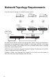
Network Topology Requirements A typical network topology for the EAP is shown below. Enwuvgt Master EAP Member EAP Member EAP Internet Router Switch The EAP120 and EAP220 provide two management modes: Cluster and Standalone. By default,the management mode is Cluster. In this mode, all EAPs in the same LAN will form a cluster, and a Master EAP will be elected among them to manage other EAPs, called Member EAPs. A DHCP server is required in the local network to assign IP addresses to the EAPs.
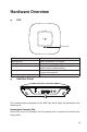
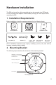
Hardware Overview ■■ LED System LED LED Status Flashing green Solid green Flashing red Indication System initialization is complete. The device is working properly. System errors. RAM, Flash, Ethernet, WLAN or firmware may be malfunctioning. Flashing yellow Firmware update is in progress. Do not disconnect or power off the device. Alternating red/green/yellow twice The device is being reset.
RESET With the device powered on, press and hold the RESET button for about 8 seconds until the LED flashes Red/Green/Yellow alternatively twice, then release the button. The device will restore to factory default settings. CONSOLE This port is used to connect to the serial port of a computer or a terminal to check and monitor system information of the device.
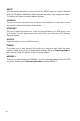
Hardware Installation The EAP can be wall or ceiling-mounted and can be powered via a PSE device or the provided power adapter. Please suitably arrange your wire layout before mounting the EAP. 1.
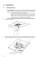
3. Installation ■■ Ceiling Mounting Note: Make sure the thickness of the ceiling is less than 18mm and the ceiling can bear at least five kilograms. It is NOT recommended to mount the EAP on a low-strength material, such as gypsum ceiling panel. If no other choice is available, make sure you add a piece of strong material under the wing nuts to ensure the EAP is mounted solidly. ■■ ■■ 1. Remove the ceiling tile. 2. Place the mounting bracket in the center of the ceiling tile.
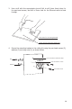
3. Use a drill with the appropriate size drill bit to drill three 4mm holes for the pan-head screws, and drill a 10mm hole for the Ethernet cable to feed through. 4mm hole for mounting bracket 10mm hole for Ethernet cable feed 4. Secure the mounting bracket to the ceiling tile using the pan-head screws (3), washers (3) and wing nuts (3), as shown below.
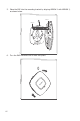
5. Place the EAP into the mounting bracket by aligning ARROW 1 with ARROW 2, as shown below. ARROW 1 ARROW 2 RESET CONSOLE ETHERNET ON/OFF POWER 6. 07 Turn the EAP clockwise until it locks into place.
7. Feed the Ethernet cable through the hole and set the ceiling tile back into place. 8. Connect the Ethernet cable to the Ethernet port. ■■ Wall Mounting There are two wall-mounting slots on the back of the mounting bracket. To mount the EAP on a wall, please follow the steps below. 1. Make two small pencil marks on the wall. The distance between the two marks should be 98.6mm. Wall L L=98.6mm 2.
Wall 4mm in diameter 3. Insert the plastic wall anchors into the 4mm holes and secure the mounting bracket to the wall by driving the self-tapping screws into the anchors. 4. Place the EAP into the mounting bracket by aligning ARROW 1 with ARROW 2, and turn the EAP clockwise to lock it into place. 4. Powering Mode The EAP can be powered via a PSE device (e.g., a PoE switch) or its power adapter. ■■ Via PSE Device TL-SG3424P EAP220 2 1 1.
Via Power Adapter ■■ Socket TL-SG2008 EAP220 Socket 1. Plug one end of the provided power adapter into the power port of the EAP, and the other end to a standard electrical wall socket. 2. Press the ON/OFF button on the interface panel of the EAP.
Getting Started with EAP The following content will guide you to quickly set up a wireless network connection with several EAPs, and login to the management page to configure the EAPs. The management host can connect to the Master EAP wirelessly or with wires. Wireless Login is conveniently recommended. Option 1: Wireless Login Internet Router Switch Master EAP Member EAP Member EAP Cluster Management Host Step 1: Power on Power on the EAPs.
Step 2: Wireless Access 1. Make sure the management host is set to obtain an IP address automatically. 2. Join the wireless network using the default SSID TP-LINK_2.4GHz_XXXXXX or TP-LINK_5GHz_XXXXXX, where XXXXXX represents the last 6 characters of the EAP's MAC address. Password is not required. Step 3: Quick Setup 1. Open a web browser and type in http://tplinkeap.net to access the EAP's web management page. Use admin (all lowercase) for both username and password to login.
Step 1: Power on Power on the EAPs. The EAP that first completes system initialization will be selected as the Master EAP. Step 2: Wired Access 1. Make sure the management host is set to obtain an IP address automatically. 2. Access your DHCP server and locate the IP address of the EAPs. Step 3: Quick Setup 1. Open a web browser and type in the IP address of the Master EAP to login to the web server. The default user name and password are admin (all lowercase).
Q&A Q1. Can Master EAP work as an access point? Yes. In addition to managing and monitoring Member EAPs, the Master EAP is equipped with features and functions of an AP, providing wireless access to clients. Q2. What is the maximum number of EAPs in a Cluster? The maximum number of EAPs in a cluster is 24. Q3. Can EAP120 be in the same Cluster with EAP220? No, EAP120 and EAP220 cannot be in the same cluster. Only the EAPs of the same model can be clustered together.
Specifications Models HARDWARE FEATURES Interface EAP120 EAP220 10/100/1000Mbps Ethernet port (RJ-45) Console port (RJ-45) Power connector (DC-2) Kensington lock slot Buttons RESET ON/OFF (for power supply) PoE Compatible 802.3af Power Supply PoE (36~57VDC, 0.2A Max) PoE (36-57VDC, 0.4A Max) or External 12VDC/1A Power or External 12VDC/1.5A Supply Power Supply Maximum Power Consumption 4.4W 9.
Technical Support ■■ ■■ ■■ For more help, please go to: http://www.tp-link.com/en/support/faq To download the latest firmware, driver, utility and user guide, please go to: http://www.tp-link.com/en/support/download For all other technical support, please contact us using the information below: Global Tel: +86 755 2650 4400 Fee: Depending on rate of different carriers, IDD. E-mail: support@tp-link.
Russian Federation Tel: 8 (499) 754 5560 (Moscow NO.) 8 (800) 250 5560 (Toll-free within RF) E-mail: support.ru@tp-link.com Service time: From 09:00 to 21:00 (Moscow time) *Except weekends and holidays in RF Singapore Tel: +65 6284 0493 Fee: Depending on rate of different carriers. E-mail: support.sg@tp-link.com Service time: 24hrs, 7 days a week Switzerland Tel: +41 (0) 848 800 998 (German Service) Fee: 4-8 Rp/min, depending on rate of different time. E-mail: support.ch@tp-link.
FCC STATEMENT This equipment has been tested and found to comply with the limits for a Class A digital device, pursuant to part 15 of the FCC Rules. These limits are designed to provide reasonable protection against harmful interference when the equipment is operated in a commercial environment. This equipment generates, uses, and can radiate radio frequency energy and, if not installed and used in accordance with the instruction manual, may cause harmful interference to radio communications.
Safety Information 1) When the product has a power button, the power button is one of the way to shut off the product. When there is no power button, the only way to completely shut off the power is to disconnect the product or the power adapter from the power source. 2) Do not attempt to disassemble the product, or make repairs yourself. You run the risk of electric shock, and voiding the limited warranty. If you need service, please contact us. 3) Avoid water and wet locations.
COPYRIGHT & TRADEMARKS Specifications are subject to change without notice. is a registered trademark of TP-LINK TECHNOLOGIES CO., LTD. Other brands and product names are trademarks of their respective holders. No part of the specifications may be reproduced in any form or by any means or used to make any derivative such as translation, transformation, or adaptation without permission from TP-LINK TECHNOLOGIES CO., LTD. Copyright © 2014 TP-LINK TECHNOLOGIES CO., LTD. All rights reserved.