¾ Image Size: Specify the image size when the network camera transmits. You can choose among 640 x 480, 320 x 240, and 160 x 120. ¾ Frame Rate: Set the frame rate of the MJPEG image. You can choose values from 1, 2, 3, 4, 5, 7, 10, and 15 fps. The unit “fps” stands for “frames per second”. ¾ Quality: z Auto: The quality will be automatically decided. z Fixed Quality: You can select the value of quality among Medium, Standard, Good, Detailed and Excellent.
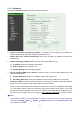
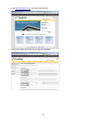
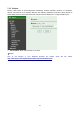
7.3.1 Information The page of Information displays the MAC address of the device. ¾ Obtain an IP address automatically (DHCP): If a DHCP server is installed on the network, to select this while the IP address is assigned by the DHCP server. ¾ Obtain DNS server address automatically: Select this to obtain the address of DNS server automatically. ¾ Use the following IP address: Select this when the fixed IP address is set. ¾ ¾ z IP address: Enter the IP address of the device.
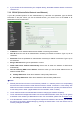
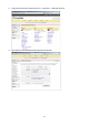
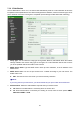
2. If you connect the IP Camera with your computer directly, the default network domain of camera is 192.168.1.xx. 7.3.2 PPPoE (Point-to-Point Protocol over Ethernet) If your ISP provides Dynamic IP with authentication by username and password, type all PPPoE information in this part. When you use the PPPoE function, you need to turn on the DDNS or IP Notification function at same time. ¾ IP Address: The IP address obtained at the PPPoE connecting with network.
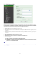
7.3.3 DDNS (Dynamic DNS) DDNS is a system which allows the domain name data held in a name server to be updated in real time. The most common use for DDNS is allowing an internet domain name to be assigned to a computer with a varying/dynamic IP Address. This makes it possible for other sites on the internet to establish connection to the machine without needing to track the IP Address themselves. ¾ Server name: Choose the DDNS Server from the list.
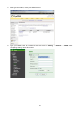
1. Login http://www.dyndns.org, click the Create Account. 2. Input all information and follow step by step with DynDNS.
3. Login with new account and click Account My Hosts Add Host Services. 4. Type domain in the Hostname field and select sub-domain.
5. After type information, check your DDNS service. 6. Type your DDNS User ID, Password and Host name in Setting Network DDNS. After completing setting, reboot IP Camera.
7.3.4 UPnP (Universal Plug and Play) You can select UPnP function “On” or “Off”. If a router is used to access to internet and it supports UPnP IGD function, please tick Turn On UPnP port forwarding. ¾ HTTP port: The default HTTP port is 80. Or the port number can be entered, ranged from 1024 to 65535. ¾ SSL port: The default SSL port is 443. Or the port number can be entered, ranged from 1024 to 65535. ¾ MPEG4 RTSP port: The default MPEG-4 RTSP Port is 554.
7.3.5 Bonjour Bonjour, also known as zero-configuration networking, enables automatic discovery of computers, devices, and services on IP networks. Bonjour uses industry standard IP protocols to allow devices to automatically discover each other without the need to enter IP addresses or configure DNS servers. ¾ Device Name: Enter Device Name as you wish. ) Note: How to use Bonjour in your Windows Browser UI? Please http://www.apple.com/support/downloads/bonjourforwindows.html.
7.3.6 IP Notification Once IP Notification is set to "On", the camera will automatically send an e-mail notification to tell users its updated network parameters if the network settings about IP address, network connection type, HTTP port or wireless connection is changed or completed. (Some settings will take effect after rebooting.) ¾ Notify Type: You can select the notify type among DHCP, Static IP, and PPPoE.
¾ SMTP: Select if SMTP authentication is necessary when an e-mail is sent. ¾ POP before SMTP: Select if POP before SMTP authentication is necessary when an e-mail is sent. z POP server name: It is necessary when the POP before SMTP is selected in Authentication. Type the POP (receiving mail) server name up to 64 characters, or type the IP address of the POP server. This setting is necessary when the SMTP server which sends e-mails performs authentication using the POP user account.
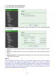
¾ Status of Wireless Networks The list above is the result of network scan. The network currently linked to will be shown in blue. The following information is provided. ¾ z ESSID - The name of a wireless network (or ad-hoc device). If the same name occurs several times this means that several access points for that network were found. The camera cannot be configured to only associate with one particular access point.
z ESSID (ESSID is sometimes written as SSID) - This is the name of the wireless network to which the camera is ready to connect. The field accepts up to 32 alphanumeric characters. The name must be exactly the same as that used in the wireless access point; otherwise, the connection will not be established. Leaving this field blank means the camera will attempt to access the nearest unsecured network. There are two methods to enter the ESSID field.
9 Obtain an IP address automatically (DHCP) – If a DHCP server is installed on the network, to select this while the IP address is assigned by the DHCP server. 9 Use the following IP address - Select this when the fixed IP address is set. IP address: Enter the IP address of the camera, which must be in the same subnet with that of the desired AP/ Router. Subnet mask: Enter the subnet mask. Default gateway: Enter the default gateway.
¾ Protocol: support MSN only. ¾ Login Account: Camera will use this account to login MSN server. This MSN account should be applied form http://www.msn.com. ¾ Password: password for this msn account. ¾ Re-type password: re-type password to double confirm. ¾ Alias: This alias will display on MSN like the following which display in red frame. ¾ Port range: Camera will select one port from this port range for video transmission. ¾ Video Mode: You can select Computer View or Mobile View.
7.4 Security Click the folder of Security to display the sub folders including Account and HTTPS. 7.4.1 Account The device fault account and password setting is “admin / admin”. That means everyone who knows IP address can access the device including all configuration. It is necessary to assign a password if the device is intended to be accessed by others. ¾ User name: Set a user name between 4-16 characters. ¾ Password: Set a password between 4-16 characters.
7.4.2 HTTPS HTTPS is a URI scheme used to indicate a secure HTTP connection. It is syntactically identical to the http:// scheme normally used for accessing resources using HTTP. Use an https: //URL/ with a different default TCP port (443) and an additional encryption / authentication layer between the HTTP and TCP, you can use the IP camera through HTTPS easily by using https:// instead of http://. ¾ Create & Install: Create a self-signed certificate for HTTPS to recognize.
Chapter 8 Setting-Advanced Click the folder of Advanced to display the sub folders including PT Control, Present Position, Patrol, FTP client, SMTP, HTTP Event, Alarm Output, Schedule, Alarm Input, Alarm Buffer, Motion detection and System Log. 8.1 PT/PTZ Control In this section, it provides Pan, Tilt, Auto Pan speed control setting. ¾ Pan speed: Specify the moving speed of the left and right commands. Available options are from 0 (slowest) to 100 (fastest). The larger the value, the faster the speed.
8.2 Preset Position ¾ Set: Use it to save the camera position to a preset number. Carry out the following steps. z Move the camera to the position to be saved while you are checking the image with the main console. z Write the preset position name in “Preset Pos. Name text” box. z Click the Set. The camera position is saved. z If want to set this position as home position, click Home option on. Click the Set. The camera position is saved as home position.
¾ Delete: Select a preset number from 1 to 32 in the list box. Use it to delete a specific preset position setting. 8.3 Patrol There are four patrol tours to set for composing different preset positions. Each one lists up to 8 positions which can be programmed, and the camera moves to the programmed positions sequentially. The camera stops when it moves to the last preset position. ¾ Tour name: Rename the tour name. ¾ Tour position z Order: There are 8 orders to select for camera directions.
¾ z Tour Start: To click Tour Start, and then the camera will start the preset patrol tour. z Tour Stop: While the camera moves on patrol tour, click Tour Stop to stop the patrol tour. Carry out the following steps: 1. Click Order and choose one of eight orders. 2. Click Select Pos. and choose one of the preset positions. 3. Fill in the Waiting time. 4. Click Set, and then the tour position is saved. 5. Follow the steps to set the other orders. 6. Click the OK to save the tour. 8.
¾ Passive mode: Set whether you use the passive mode of FTP server or not when connecting to FTP server. Select On to connect to FTP server using the passive mode. 8.4.2 Alarm Sending Set to forward the image file to the specified FTP server linked with the alarm detection by the built-in motion detection function. Select On to send the image file to FTP server linked with the alarm detection. ¾ Remote Path: Type the path to the destination in FTP server up to 64 characters.
) Note: You can set motion detection at motion detection page. (Please go to “Setting Advanced Motion Detection Setting”. For more details, please refer to Section 8.10.) z Alarm Input: Select the connected alarm. 9 Alarm input1: The external sensor which is connected to Alarm input1 of the alarm input.
) Note: You can set the alarm input function at Alarm Input page. (Please go to “Setting Advanced Alarm Input Setting”. For more details, please refer to Section 8.9.) ¾ Effective period: Set the period when the periodical sending is effective. z Always: The periodical sending is always effective. z Schedule: You can specify the period when the periodical sending is effective in the Schedule setting in the other section. ) Note: You can set schedule function at Schedule page.
¾ Effective period: Set the period when the periodical sending is effective. z Always: The periodical sending is always effective. z Schedule: You can specify the period when the periodical sending is effective in the Schedule setting in the other section. ) Note: You can set schedule function at schedule page. (Please go to “Setting Advanced Schedule Setting”. For more details, please refer to Section 8.8.) 8.5 SMTP SMTP is used for sending an image via e-mail.
) Note: If you use g-mail as your mail server, you should set 587 as your port number and tick SSL box. ¾ Authentication: z Off: No authentication is necessary when an email is sent. z On: Authentication is necessary when an e-mail is sent. To set the authentication, please select one from SMTP and POP before SMTP. ¾ SMTP: Select it if SMTP authentication is necessary when an e-mail is sent. ¾ POP before SMTP: Select it if POP before SMTP authentication is necessary when an e-mail is sent.
8.5.2 Alarm Sending Set to send the mail with connection to the alarm detection by the built-in motion detection function. Select On to send the image file to SMTP server linked with the alarm detection. ¾ Alarm sending: Select On to set to send mail with connection to the alarm detection. ¾ File attachment: Set whether an image file is attached to the mail sent or not. When On is selected, the image file made by the settings below is attached. When Off is selected, only the message is sent.
) Note: You can set motion detection at motion detection page. (Please go to “Setting Advanced Motion Detection Setting”. For more details, please refer to Section 8.10.) z Alarm Input: Select the connected alarm. 9 Alarm input1: The external sensor which is connected to Alarm input1 of the alarm input.
) Note: You can set the alarm input function at Alarm Input page. (Please go to “Setting Advanced Alarm Input Setting”. For more details, please refer to Section 8.9.) ¾ Effective period: Set the period when the periodical sending is effective. z Always: The periodical sending is always effective. z Schedule: You can specify the period when the periodical sending is effective in the Schedule setting in the other section. ) Note: You can set schedule function at Schedule page.
¾ Interval: Set the time interval of the periodical sending. Min value is 30 min and Max value is 24 hour. ¾ Effective period: Set the period when the periodical sending is effective. z Always: The periodical sending is always effective. z Schedule: You can specify the period when the periodical sending is effective in the schedule setting in the other section. Please check “Setting Basic Advance Schedule Setting.” ) Note: You can set schedule function at schedule page.
8.6.2 Alarm Sending Set to send the commands via the alarm detection, external sensor input or built-in motion detection function. Select On to send the commands to HTTP server linked with the alarm detection. ¾ Alarm sending: Select On to set to send command with connection to the alarm detection. ¾ Alarm z Motion Detection: Click it on for using Motion Detection function as a sensor. You can set motion detection function at the motion detection function page.
) Note: 1. You can set motion detection at motion detection page. (Please go to “Setting Advanced Motion Detection Setting”. For more details, please refer to Section 8.10.) 2. Motion Detection works only when the MPEG4 function is On. 9 Parameter: the parameter of CGI (defined in URL of HTTP General) is from your target device. For example, move=down.
9 z Message: message will show up in the form of Message = PTZ down. If your target device didn’t support the parameter of message, you can’t see the message. So you can just take the message as a note. For example: PTZ down. Alarm Input: Select the connected alarm. 9 Alarm input1: The external sensor which is connected to sensor input1 of the alarm input. ) Note: You can set the alarm input function at Alarm Input page. (Please go to “Setting Advanced Alarm Input Setting”.
) Note: You can set schedule function at Schedule page. (Please go to “Setting Advanced Schedule Setting”. For more details, please refer to Section 8.8.) 8.7 Alarm Output When you click Alarm output on the setting-advanced menu, the Setting menu appears. You can set in this menu to control the alarm out of I/O port on the rear of the device linked to the alarm detection and the timer. Alarm output: To activate the Alarm output function, select On.
) Note: You can set the alarm input function at alarm input page. (Please go “Setting Advanced Alarm input Setting”) ¾ Alarm Duration: There are up to 60 second options to choose for alarm duration interval. ¾ Effective period: Set the period when the periodical sending is effective. z Always: The periodical sending is always effective. z Schedule: You can specify the period when the periodical sending is effective in the Schedule setting in the other section.
¾ Use the same time schedule every day: When this is checked, the Start time and End time set to Mon (Monday) are applied to all days. In this case, the Start time and End time of the other days than Mon (Monday) cannot be input. 8.9 Alarm Input When you click Alarm Input on the setting-advanced menu, the Setting menu appears. You can set in this menu to control the external alarm input of I / O port on the rear of the device linked to FTP, SMTP, and HTTP sending function.
¾ Motion Detection 1: Click it on for using Motion Detection 1 function as a sensor. You can adjust and move the detecting zone by using mouse. ¾ Motion Detection 2: Click it on for using Motion Detection 2 function as a sensor. You can adjust and move the detecting zone by using mouse. ¾ Motion Detection 3: Click it on for using Motion Detection 3 function as a sensor. You can adjust and move the detecting zone by using mouse. z Threshold: It means the extent which the alarm will be triggered.
¾ Enable remote log: Enables user to send the log data to a specified log server.
Appendix A. FRAME-RATE AND BITRATE TABLE Help to set IP Camera with your network environment to access Internet. Base on your network UPLOAD environment to choose the suitable Image-Quality setting. For example, if the network environment is ADSL 256Kb/s (upload)/2Mb/s (download), the most fluent Image-Quality needs to set up under 256 Kb situation. A.1.
320*240 512 15 600 16 160*120 1024 30 950 30 160*120 1024 15 750 16 160*120 512 30 500 30 160*120 512 15 50 16 160*120 128 30 130 30 160*120 128 15 140 16 A.3. MJPEG @ 15fps / Kbps Quality 640*480 320*240 160*120 Excellent 4000 1500 600 Detailed 2400 900 400 Good 1600 650 300 Standard 1300 500 240 Medium 900 350 170 A.4.
320*240 Medium 15 350 13 160*120 Medium 5 130 5 160*120 Excellent 15 600 13 160*120 Excellent 5 230 5 160*120 Good 15 300 13 160*120 Good 5 115 5 160*120 Medium 15 170 13 160*120 Medium 5 65 5 B. STORAGE REQUIREMENT TABLE Help to set Recording Storage System. Please refer to the following table to find out the capability for recording into your hard disk. B.1. MPEG4 Storage Requirement GB / channel / day @ 30fps Quality 640*480 320*240 160*120 Excellent 10.5 3.
640*480 2048 30 23.0 640*480 2048 15 22.2 640*480 1536 30 18.5 640*480 1536 15 17.9 640*480 1024 30 10.5 640*480 1024 15 10.5 640*480 512 30 5.3 640*480 512 15 6.3 320*240 1536 30 15.8 320*240 1536 15 16.9 320*240 1024 30 10.5 320*240 1024 15 10.5 320*240 512 30 5.8 320*240 512 15 6.3 160*120 1024 30 10.0 160*120 1024 15 7.9 160*120 512 30 5.3 160*120 512 15 0.5 160*120 128 30 1.4 160*120 128 15 1.5 B.4.
B.5. MJPEG Storage Requirement GB / channel / day Image-Size Quality Setting Frame-Rate Setting Current Bitrate 640*480 Excellent 15 42.2 640*480 Excellent 5 16.9 640*480 Good 15 16.9 640*480 Good 5 6.9 640*480 Medium 15 9.5 640*480 Medium 5 3.8 320*240 Excellent 15 15.8 320*240 Excellent 5 5.8 320*240 Good 15 6.9 320*240 Good 5 2.7 320*240 Medium 15 3.7 160*120 Medium 5 1.4 160*120 Excellent 15 6.3 160*120 Excellent 5 2.4 160*120 Good 15 3.
C. TESTING SYSTEM SPECIFICATION Software: MainConsole Version 2.6.4 Professional CPU: AMD Athlon 64*2 @3600+MHz Memory: 2048 MB (2 x 1024 DDR2-SDRAM ) Ethernet: VIA Rhine II Fast Ethernet Adapter Hard Disk: ST3250620A (250 GB) Graphic card: ATI Technologies Inc EAX1600 Series Operating System: Windows XP Professional SP2 x64 D.
Europe – EU Declaration of Conformity This device complies with the essential requirements of the R&TTE Directive 1999/5/EC.
Federal Communication Commission Interference Statement This equipment has been tested and found to comply with the limits for a Class B digital device, pursuant to Part 15 of the FCC Rules. These limits are designed to provide reasonable protection against harmful interference in a residential installation. This equipment generates, uses and can radiate radio frequency energy and, if not installed and used in accordance with the instructions, may cause harmful interference to radio communications.