TD854W 150Mbps Wireless N ADSL2+ Modem Router Rev: 1.0.
COPYRIGHT & TRADEMARKS Specifications are subject to change without notice. is a registered trademark of TP-LINK TECHNOLOGIES CO., LTD. Other brands and product names are trademarks or registered trademarks of their respective holders. No part of the specifications may be reproduced in any form or by any means or used to make any derivative such as translation, transformation, or adaptation without permission from TP-LINK TECHNOLOGIES CO., LTD. Copyright © 2011 TP-LINK TECHNOLOGIES CO., LTD.
FCC RF Radiation Exposure Statement This equipment complies with FCC RF radiation exposure limits set forth for an uncontrolled environment. This device and its antenna must not be co-located or operating in conjunction with any other antenna or transmitter. “To comply with FCC RF exposure compliance requirements, this grant is applicable to only Mobile Configurations.
TP-LINK TECHNOLOGIES CO., LTD DECLARATION OF CONFORMITY For the following equipment: Product Description: 150Mbps Wireless N ADSL2+ Modem Router Model No.: TD854W Trademark: TP-LINK We declare under our own responsibility that the above products satisfy all the technical regulations applicable to the product within the scope of Council Directives: Directives 1999/5/EC The above product is in conformity with the following standards or other normative documents ETSI EN 300 328 V1.7.
CONTENTS Package Contents......................................................................................................1 Chapter 1. Introduction...........................................................................................2 1.1 Product Overview ..................................................................................2 1.2 Main Features........................................................................................2 1.3 Conventions.................................
4.4.2 UPnP ......................................................................................................... 62 4.4.3 SNMP ........................................................................................................ 63 4.4.4 DNS........................................................................................................... 64 4.4.5 DDNS ........................................................................................................ 64 4.5 Firewall ...................
Error! AutoText entry not defined. Error! AutoText entry not defined. User Guide Package Contents The following contents should be found in your package: One TD854W 150Mbps Wireless N ADSL2+ Modem Router One Power Adapter for TD854W 150Mbps Wireless N ADSL2+ Modem Router Quick Installation Guide One RJ45 cable Two RJ11 cables One ADSL splitter One Resource CD, which includes this User Guide Note: Make sure that the package contains the above items.
Error! AutoText entry not defined. Error! AutoText entry not defined. User Guide Chapter 1. Introduction Thank you for choosing the TD854W 150Mbps Wireless N ADSL2+ Modem Router. 1.1 Product Overview The device is designed to provide a simple and cost-effective ADSL Internet connection for a private Ethernet or IEEE 802.11n/ IEEE 802.11g/ IEEE 802.11b wireless network. The TD854W connects to an Ethernet LAN or computers via standard Ethernet ports.
Error! AutoText entry not defined. Error! AutoText entry not defined. User Guide RFC-1483/2684 LLC/VC-Mux bridge/route mode RFC-1577 Classical IP over ATM RFC-2516 PPPoE RFC-2364 PPPoA ITU-T 1.610 F4/F5 OAM send and receive loop-back 802.
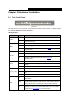
Error! AutoText entry not defined. Error! AutoText entry not defined. User Guide Chapter 2. Hardware Installation 2.1 The Front Panel Figure 2-1 The LEDs locate on the front panel. They indicate the device’s working status. For details, please refer to Error! Reference source not found.. LED Explanation Name Power ADSL Status Indication On The modem router is powered on. Off The modem router is off. Please ensure that the power adapter is connected correctly.
Error! AutoText entry not defined. Error! AutoText entry not defined. User Guide Note: 1. If the ADSL LED is off, please check your Internet connection first. Refer to 2.4 Connecting the Modem Router for more information about how to make Internet connection correctly. If you have already made a right connection, please contact your ISP to make sure if your Internet service is available now. 2. If the Internet LED is off, please check your ADSL LED first.
Error! AutoText entry not defined. Error! AutoText entry not defined. User Guide 2.3 The Side Panel Figure 2-3 WLAN: Press this button to enable or disable the Wireless LAN interface. QSS: This button is used for QSS setting. For detailed information, please refer to 4.2.3.6 QSS. ON/OFF: The switch for the power. 2.4 Installation Environment The Product should not be located where it will be exposed to moisture or excessive heat.
Error! AutoText entry not defined. Error! AutoText entry not defined. User Guide Before installing the device, please make sure your broadband service provided by your ISP is available. If there is any problem, please contact your ISP. Before cable connection, cut off the power supply and keep your hands dry. You can follow the steps below to install it. Step 1: Connect the ADSL Line.
Error! AutoText entry not defined. Error! AutoText entry not defined.
Error! AutoText entry not defined. Error! AutoText entry not defined. User Guide Chapter 3. Quick Installation Guide 3.1 Configure PC After you directly connect your PC to the TD854W or connect your adapter to a Hub/Switch which has connected to the Router, you need to configure your PC’s IP address. Follow the steps below to configure it. Step 1: Click the Start menu on your desktop, right click My Network Places, and then select Properties (shown in Figure 3-1).
Error! AutoText entry not defined. Error! AutoText entry not defined. User Guide Figure 3-2 Step 3: Select General tab, highlight Internet Protocol (TCP/IP), and then click the Properties button.
Error! AutoText entry not defined. Error! AutoText entry not defined. User Guide Figure 3-3 Step 4: Configure the IP address as Figure 3-4 shows. After that, click OK. Figure 3-4 Note: You can configure the PC to get an IP address automatically, select “Obtain an IP address automatically” and “Obtain DNS server address automatically” in the screen above. Now, you can run the Ping command in the command prompt to verify the network connection.
Error! AutoText entry not defined. Error! AutoText entry not defined. User Guide Figure 3-5 If the result displayed is similar to the screen shown below, it means that your PC has not connected to the Router. Figure 3-6 You can check it follow the steps below: 1) Is the connection between your PC and the Router correct? The LEDs of LAN port which you link to the device and the LEDs on your PC's adapter should be lit.
Error! AutoText entry not defined. Error! AutoText entry not defined. User Guide Figure 3-7 Step 1: Select the Wizard tab and you will see the next screen. Figure 3-8 Step 2: Configure the Router with the information provided by your ISP, including VPI/VCI, Connection Mode and the following parameters. Take PPPoE for example, you need to enter Username, Password and DNS parameters. All these information are provided by your ISP. After that, click the next button to continue.
Error! AutoText entry not defined. Error! AutoText entry not defined. User Guide Figure 3-9 Step 3: Choose to enable your wireless network or not. If it’s enabled, you need to create a name for your wireless network. It’s recommended that the name be unique and easy to remember. You can also keep default without the device being affected. Select an Encryption and Authentication Mode for the security of your wireless network, and then enter the key in the corresponding field.
Error! AutoText entry not defined. Error! AutoText entry not defined. User Guide If the WLAN is enabled, the wireless function will be available even without the external antenna because of an additional printed antenna. To adopt the wireless security protection measures, please refer to Section 4.2.3.3. Step 4: Click the Apply Changes button to finish the wizard.
Error! AutoText entry not defined. Error! AutoText entry not defined. User Guide Chapter 4. Software Configuration This User Guide recommends using the “Quick Installation Guide” for first-time installation. For advanced users, if you want to know more about this device and make use of its functions adequately, maybe you will get help from this chapter to configure the advanced settings through the Web-based Utility. After your successful login, you can configure and manage the device.
Error! AutoText entry not defined. Error! AutoText entry not defined. User Guide Figure 4-1 Click the Refresh button to refresh immediately. 4.1.1.2 ADSL Choose “Status→Device Info→ADSL” menu, and you will be able to view the ADSL configuration.
Error! AutoText entry not defined. Error! AutoText entry not defined. User Guide Figure 4-2 Click the Retrain button to retrain the information again. Click the Refresh button to refresh immediately. 4.1.2 Statistics Choose “Status→Statistics” menu, and you will be able to view the network traffic.
Error! AutoText entry not defined. Error! AutoText entry not defined. User Guide Figure 4-3 Click the Refresh button to refresh immediately. 4.1.3 Wizard Please refer to " 3.2: Login". 4.2 Setup Choose “Setup”, you can see the next submenus: WAN, LAN and WLAN. Click any of them, and you will be able to configure the corresponding function. 4.2.1 WAN 4.2.1.1 WAN Back to LED Explanation Choose “Setup→WAN→WAN” menu, you can configure the parameters for WAN in the next screen (shown in Figure 4-4).
Error! AutoText entry not defined. Error! AutoText entry not defined. User Guide Figure 4-4 Current ATM VC Table: ATM settings are used to connect to your ISP. Your ISP provides VPI (Virtual Path Identifier), VCI (Virtual Channel Identifier) settings to you. In this Device, there is one VC configured by default. You can totally setup 8 VCs on different encapsulations, if you apply 8 different virtual circuits from your ISP. You need to activate the VC to take effect.
Error! AutoText entry not defined. Error! AutoText entry not defined. User Guide Encapsulation: Specifies the type of Multiplexing, either LLC or VC-Mux. Please note that VC-Mux is not available for IPoA channel mode. Channel Mode: There are six channel modes, 1483 Bridged, 1483 MER, PPPoE, PPPoA, 1483 Routed and IPoA. Please choose the mode that you want to use. Enable NAPT: Choose to enable the NAPT function or not. Enable IGMP: Choose to enable the IGMP function or not.
Error! AutoText entry not defined. Error! AutoText entry not defined. User Guide Undo: Click this button to abandon your operation. Refresh: Click this button to refresh the ATM VC table. Note: After configuration, you need to click the Save button on the left panel to make your configuration take effect. 4.2.1.2 ATM Choose “Setup→WAN→ATM” menu, you can configure the parameters for the ATM of your ADSL Router in the next screen (shown in Figure 4-4).
Error! AutoText entry not defined. Error! AutoText entry not defined. User Guide Figure 4-6 After configuration, click Apply Changes button to save your changes. Note: After saving your configuration, you need to click the Save button on the left panel to make your configuration take effect. 4.2.2 LAN 4.2.2.1 LAN Choose “Setup→LAN→LAN” menu, and you will see the LAN Interface Setup screen (shown in Figure 4-7). Here you can change IP address, subnet mask and other parameters for LAN interface.
Error! AutoText entry not defined. Error! AutoText entry not defined. User Guide Figure 4-7 Interface Name: Displays the name of the LAN interface for the device. IP Address: The Router’s local IP Address. You can access to the Web-based Utility via the IP Address, the default value is 192.168.1.1. You can change the IP address if needed. The LAN IP address is private to your internal network and cannot be seen on the Internet. Subnet Mask: The subnet mask of the ADSL Router’s LAN interface.
Error! AutoText entry not defined. Error! AutoText entry not defined. User Guide New MAC Address: This field allows you to add a new MAC address to the Current Allowed MAC Address Table. To add a new MAC address, enter the MAC address and then click Add button. Current Allowed MAC Address Table: Displays the current allowed MAC address. Click the Delete button and then the corresponding MAC address will be deleted. After configuration, click Apply Changes button to save your changes.
Error! AutoText entry not defined. Error! AutoText entry not defined. User Guide DHCP Mode: Options available are None, DHCP Relay and DHCP Server. 1) None: In this mode, the Modem Router will do nothing when the host requests an IP address by DHCP protocol. The screen will be shown as in Figure 4-9. Figure 4-9 2) DHCP Relay: In this mode, the Router will work as a DHCP Relay.
Error! AutoText entry not defined. Error! AutoText entry not defined. User Guide Figure 4-11 IP Pool Range: Specify the start and end IP address for the DHCP server's IP assignment. The default start and end IP Address are 192.168.1.100 and 192.168.1.200 separately. Please note that both addresses should be smaller than 192.168.1.254. Default Gateway: The default gateway address. Max Lease Time: The time that the DHCP client is allowed to maintain the assigned dynamic IP.
Error! AutoText entry not defined. Error! AutoText entry not defined. User Guide Figure 4-12 Device name: Give a name for the class of your device, such as PC, Phone, TV, etc. Start address: Specify the start address. End address: Specify the end address. Router address: Enter the IP address of the Modem Router. Option60: A string of n octets, interpreted by DHCP servers, used by DHCP client to optionally identify the vendor type and configuration of a DHCP client.
Error! AutoText entry not defined. Error! AutoText entry not defined. User Guide Figure 4-13 IP Address: Enter the IP address desired to be assign to the client. Mac Address: Enter the MAC address of the client. After configuration, click Apply Changes button to save your changes. Note: After saving your configuration, you need to click the Save button on the left panel to make your configuration take effect. 4.2.
Error! AutoText entry not defined. Error! AutoText entry not defined. User Guide Figure 4-14 Disable Wireless LAN Interface: Choose to disable the Wireless function of the ADSL Router. Band: Options available are 2.4 GHz (B), 2.4 GHz (G), 2.4 GHz (B+G), 2.4 GHz (N), 2.4 GHz (G+N), and 2.4 GHz (B+G+N). Mode: Options are AP and AP+WDS. If AP+WDS is selected, then the Router can bridge two or more WLANs. SSID: Wireless network name shared among all points in a wireless network.
Error! AutoText entry not defined. Error! AutoText entry not defined. User Guide Note: After saving your configuration, you need to click the Save button on the left panel to make your configuration take effect. 4.2.3.2 MSSID Choose “Setup→WLAN→MSSID” menu, and you will see the Wireless Multiple BSSID Setup screen (shown in Figure 4-15). Here you can configure the parameters for the virtual access point.
Error! AutoText entry not defined. Error! AutoText entry not defined. User Guide SSID: Wireless network name shared among all points in a wireless network. The SSID must be identical for all devices in the wireless network. It is case-sensitive and must not exceed 32 characters (use any of the characters on the keyboard). Make sure this setting is the same for all stations in your wireless network. Type the desired SSID in the space provided.
Error! AutoText entry not defined. 1. Error! AutoText entry not defined. User Guide WEP WEP (Wired Equivalent Privacy) is a data privacy mechanism based on a 64-bit and 128-bit shared key algorithm, as described in the IEEE 802.11g standard. To configure WEP settings, select “WEP” from the Encryption drop-down list. The options available will change to offer the appropriate settings. Figure 4-17 SSID TYPE: Select the desired wireless network to configure the security.
Error! AutoText entry not defined. Error! AutoText entry not defined. User Guide Figure 4-18 Key Length: Select the desired length. Options available are 64-bit and 128-bit. Key Format: Select the desired format. Options available are ASCII (5 characters) and Hex (10 characters). Default Tx Key: Select the desired key for the configuration. Encryption Key 1/2/3/4: Create a key for your wireless network. Use 802.
Error! AutoText entry not defined. Error! AutoText entry not defined. User Guide Figure 4-19 SSID TYPE: Select the desired wireless network to configure the security. There can be root SSID or virtual Access Point. Encryption: Select the encryption you want to use: WPA (TKIP), WPA (AES), WPA2 (AES), WPA2 (TKIP) and WPA2 Mixed is an encryption method stronger than TKIP).
Error! AutoText entry not defined. Error! AutoText entry not defined. User Guide 4.2.3.4 Access control Choose “Setup→WLAN→Access Control” menu, and you will see the Wireless Access Control screen (shown in Figure 4-20). Wireless access control function is used to allow or deny the wireless client’s access to the wireless network by MAC address. Figure 4-20 Wireless Access Control Mode: Options are “Disable”, “Allow Listed” and “Deny Listed”.
Error! AutoText entry not defined. Error! AutoText entry not defined. User Guide Figure 4-21 Fragment Threshold: This value specifies the maximum size for a packet before data is fragmented into multiple packets. If you experience a high packet error rate, you may slightly increase the Fragmentation Threshold. Setting the Fragmentation Threshold too low may result in poor network performance. Only minor reduction of the default value is recommended.
Error! AutoText entry not defined. Error! AutoText entry not defined. User Guide Broadcast SSID: When wireless clients survey the local area for wireless networks to associate with, they will detect the SSID broadcast by the Router. To broadcast the Router’s SSID, select “Enable”. If you don’t want to broadcast the Router’s SSID, select “Disable”. Note: These settings are only for more technically advanced users who have a sufficient knowledge about wireless LAN.
Error! AutoText entry not defined. Error! AutoText entry not defined. User Guide Push Button Configuration: Click Start PBC button when using PBC method for QSS configuration. 1) PBC If the wireless adapter supports QSS and the Push Button Configuration (PBC) method, you can add it to the network by PBC with the following two methods. Method One: Step 1: Press the QSS button on the front panel of the Router or click Start PBC button in Figure 4-22.
Error! AutoText entry not defined. Error! AutoText entry not defined. User Guide The QSS Configuration Screen of Wireless Adapter Method Two: Step 1: Press the QSS button on the front panel of the Router or click Start PBC button in Figure 4-22. Step 2: For the configuration of the wireless adapter, please choose “Push the button on my access point” in the configuration utility of the QSS as below, and click Next.
Error! AutoText entry not defined. Error! AutoText entry not defined. User Guide The QSS Configuration Screen of Wireless Adapter Step 3: Wait for a while until the next screen appears. Click Finish to complete the QSS configuration. The QSS Configuration Screen of Wireless Adapter 2) PIN code If the wireless adapter supports QSS and the PIN method, you can add it to the network by PIN with the following two methods.
Error! AutoText entry not defined. Error! AutoText entry not defined. User Guide Method One: Enter the PIN into my Router Step 1: For the configuration of the wireless adapter, please choose “Enter a PIN into my access point or a registrar” in the configuration utility of the QSS, and get the PIN code on the screen as below, then click Next. The QSS Configuration Screen of Wireless Adapter Step 2: For the Router, enter the PIN code of the wireless adapter in the Client PIN Number field as shown below.
Error! AutoText entry not defined. Error! AutoText entry not defined. User Guide Method Two: Enter the PIN from my Router Step 1: Get the Current PIN code of the Router from Self-PIN Number in Figure 4-23 (each Router has its unique PIN code. Here takes the PIN code 00745659 of this Router for example).
Error! AutoText entry not defined. Error! AutoText entry not defined. User Guide Comment [znh1]: 无法设置 4.2.3.7 WDS Figure 4-24 Enable WDS: Select to enable WDS. With this function enabled, the Router can bridge two or more WLANs. Add WDS AP: MAC Address: Enter the MAC Address you wish to bridge in the field. Comment: Give a comment. Note: If changes are made, after clicking Apply Changes button, a Save button will appear on the left panel.
Error! AutoText entry not defined. Error! AutoText entry not defined. User Guide Figure 4-25 Enable: Check the box to enable this function. Destination: Enter the IP network address of the final destination. It can be a subnet IP or a host address. All zeros indicate that the route entry should be used for all destinations for which no other route is defined. Subnet Mask: Enter the subnet mask of the destination.
Error! AutoText entry not defined. Error! AutoText entry not defined. User Guide Figure 4-26 RIP: Select to enable the RIP function or not. Click the Apply button to save your configuration. Interface: Select the interface on which you want to enable RIP. Recv Version: Indicate the RIP version in which information must be passed to the device. It can be accepted into its routing table.
Error! AutoText entry not defined. Error! AutoText entry not defined. User Guide Figure 4-27 Enable DMZ: Check the box to enable DMZ function. DMZ Host IP Address: Enter the specified IP Address for DMZ host on the LAN side. Click Apply Changes to save your configuration. Note: If changes are made, after clicking Apply Changes button, a Save button will appear on the left panel. You need to click the Save button to make your changes take effect. 4.3.2.
Error! AutoText entry not defined. Error! AutoText entry not defined. User Guide Figure 4-28 Usual Service Name: The Router provides some common services. Select the one you need. User-defined Service Name: If the service can not be found in the Usual Service Name drop-down list, just enter the name manually in this field instead. Protocol: The protocol used for this virtual server. WAN Setting: The WAN setting of this virtual server used; it can be interface and IP address.
Error! AutoText entry not defined. Error! AutoText entry not defined. User Guide For example: If you want to setup a FTP Server on LAN host 192.168.1.33, you can configure a virtual server rule as follows: Step 1: Select “FTP” from Usual Service Name drop-down list. Protocol, WAN Port, and LAN Open Port will be automatically filled, and you don’t need to change them. Step 2: Select the WAN Setting for the service. Step 3: Enter 192.168.1.33 in LAN IP Address field.
Error! AutoText entry not defined. Error! AutoText entry not defined. User Guide Port trigger is used to restrict certain types of data packets from your local network to Internet. Some applications require multiple connections, like Internet games, video conferencing, Internet calling and so on. These applications cannot work with a pure NAT Router. Port Trigger is used for some of these applications that can work with an NAT Router, which can be helpful in securing and restricting your local network.
Error! AutoText entry not defined. Error! AutoText entry not defined. User Guide NAT Type: It can be outgoing or incoming. Click the Apply Changes button to save your configuration. And then the trigger rule will be added to the Current Portrigger Table. Note: If changes are made, after clicking Apply Changes button, a Save button will appear on the left panel. You need to click the Save button to make your changes take effect. 4.3.2.
Error! AutoText entry not defined. Error! AutoText entry not defined. User Guide “Global End IP”. Local Start IP / Local End IP: Enter the local IP Address you plan to map to. Local Start IP is the starting local IP address and Local End IP is the ending local IP address. If the rule is for all local IPs, then the Start IP is 0.0.0.0 and the End IP is 255.255.255.255. Global Start IP / Global End IP: Enter the global IP Address you want to do NAT.
Error! AutoText entry not defined. Error! AutoText entry not defined. User Guide Figure 4-32 IP QoS: Enable or disable the IP QoS function on the device. QoS Policy: Policy of QoS. The traffic will be classified on the base of this policy. It can be based on stream, 802.1p or DSCP. Schedule Mode: The schedule mode of the IP QoS function, it can be “strict prior” or “WFQ (4:3:2:1)”.
Error! AutoText entry not defined. Error! AutoText entry not defined. User Guide Note: If changes are made, after clicking Apply Changes button, a Save button will appear on the left panel. You need to click the Save button to make your changes take effect. 4.3.3.1 Stream If the QoS policy is “stream based”, you should configure the QoS rule. Figure 4-33 Src IP: The source IP address of the rule. Src Mask: The source mask of the rule. Dest IP: The destination IP address of the rule.
Error! AutoText entry not defined. Error! AutoText entry not defined. User Guide Set Priority: The priority of the rule. It can be p0(highest), p1, p2, p3(lowest). The traffic matches the rule will be assigned the priority you have configured. Insert or modify QoS mark: You can insert or modify the DSCP or 802.1p tag. The traffic matches the rule will be added or modified the mark. Note: If you select 802.1p tag, please make sure 802.1q is enabled in specified WAN interface; otherwise 802.
Error! AutoText entry not defined. Error! AutoText entry not defined. User Guide 4.3.3.2 802.1p If the QoS policy is “802.1p based”, you should configure the 802.1p setting. Figure 4-34 802.1p tag: The number of 802.1p tag. Send priority: The priority to transmit. The traffic matches the 802.1p filed will be assigned this priority. Modify: Click this button to modify your configuration. 802.1p rule list: Shows the current rules on the device. 4.3.3.
Error! AutoText entry not defined. Error! AutoText entry not defined. User Guide Figure 4-35 DSCP tag: The value of the DSCP filed. Transmit prior: The priority to transmit. The traffic matches the DSCP filed will be assigned this priority. Dscp rule list: Shows the current rules on the device. 4.3.4 CWMP Choose “Advanced→CWMP”, you can configure the CWMP function in the screen (shown in Figure 4-36). Here you may change the setting for the ACS’s parameters.
Error! AutoText entry not defined. Error! AutoText entry not defined. User Guide information, diagnoses the devices and configures the devices automatically via ACS (Auto-Configuration Server). Figure 4-36 ACS parameters Enable: Enable or disable the CWMP. URL: Enter the website of ACS which is provided by your ISP. User Name/Password: Enter the User Name and password the device should use when connecting to the ACS.
Error! AutoText entry not defined. Error! AutoText entry not defined. User Guide Port: The port of the device ConnectionRequestURL. 4.3.5 Port mapping Choose “Advanced→Port Mapping”, you can configure the mapping group in the screen (shown in Figure 4-37). The device provides multiple interface groups, up to five interface groups are supported including one default group. Traffic coming from one interface of a group can only be flowed to the interfaces in the same interface group.
Error! AutoText entry not defined. Error! AutoText entry not defined. User Guide Figure 4-37 You can enable or disable the port mapping function of the device by the select radio button. If “Enable” radio is selected, you can configure the mapping group as follow steps. 1. Select a group (Group 1, Group 2, Group3 or Group 4) from the table, then you can see the available interface (LAN and WAN) and grouped interface list 2.
Error! AutoText entry not defined. 4. Error! AutoText entry not defined. User Guide Click the Save button on the left panel to make the changes take effect. 4.3.6 Others Choose “Advanced→Others”, you can configure the client limit settings in the screen (shown in Figure 4-38). Client limit allows you to force how many devices can access to the internet. Here you can enable or disable the client limit function and the maximum device to access to the internet.
Error! AutoText entry not defined. Error! AutoText entry not defined. User Guide Figure 4-39 Note: If changes are made, after clicking Apply Changes button, a Save button will appear on the left panel. You need to click the Save button to make your changes take effect. 4.4.2 UPnP Choose “Service→UPnP” menu, you can configure the UPnP in the screen (shown in Figure 4-40).
Error! AutoText entry not defined. Error! AutoText entry not defined. User Guide Note: If changes are made, after clicking Apply Changes button, a Save button will appear on the left panel. You need to click the Save button to make your changes take effect. 4.4.3 SNMP Choose “Service→SNMP”, you can see the SNMP screen (shown in Figure 4-41).
Error! AutoText entry not defined. Error! AutoText entry not defined. User Guide Community name (read-write): Name of the read-write community. This read-write community allows read and write operation to all objects defines as read-writable in the MIB. 4.4.4 DNS Choose “Service→DNS”, you can see the DNS screen (shown in Figure 4-42).
Error! AutoText entry not defined. Error! AutoText entry not defined. User Guide Figure 4-43 DDNS provider: There are two DDNS provider to be selected in order to register your device, DynDNS.org and TZO. Hostname: Domain name to be registered with the DDNS server. Interface: The WAN interface over which your device will be accessed. Enable: Check to enable the registration account for the DDNS server. DynDns Settings: Username: Username assigned by the DDNS provider.
Error! AutoText entry not defined. Error! AutoText entry not defined. User Guide 4.5 Firewall Choose “Firewall”, you can see the next submenus: Click any of them, and you will be able to configure the corresponding function. 4.5.1 MAC Filter Choose “Firewall→MAC Filter” menu, and you will see the next screen (shown in Figure 4-44). In order to management your local network better, you can use the MAC address filter function to control the internet access. Here you can set the MAC filtering rules.
Error! AutoText entry not defined. Error! AutoText entry not defined. User Guide Action: The action of the filter entry, it can be “Deny” or “Allow”. If the action is “Deny”, the connection matches the filter rule will be denied, if the action is “Allow”, the connection matches the filter rule will be allowed. Source MAC: The source MAC address of the filter entry. Empty means matching any source MAC address. Destination MAC: The destination MAC address of the filter entry.
Error! AutoText entry not defined. Error! AutoText entry not defined. User Guide Figure 4-45 SPI Firewall: Choose to enable or disable the SPI firewall. Rule Action: The filter mode of this entry, it can be “Permit” and “Deny”. If the mode is “Permit”, the IP connection matches the rule will be permitted; if the mode is “Deny”, the IP connection matches the rule will be denied. Protocol: The protocol of this entry, it can be “IP”, “ICMP”, “TCP” and “UDP”.
Error! AutoText entry not defined. Error! AutoText entry not defined. User Guide Note: If changes are made, after clicking Apply Changes button, a Save button will appear on the left panel. You need to click the Save button to make your changes take effect. 4.5.3 URL Filter Choose “Firewall→URL Filter” menu, and you will see the next screen (shown in Figure 4-46). Here you can specify which site can’t be accessed based on URL to secure or restrict your local network.
Error! AutoText entry not defined. Error! AutoText entry not defined. User Guide Step 2: Enter “yahoo.com” in the Keyword field. Step 3: Finally click the AddKeyword to save the entry. Note: If changes are made, after clicking Apply Changes button, a Save button will appear on the left panel. You need to click the Save button to make your changes take effect. 4.5.4 ACL Choose “Firewall→ACL”, you can see the next screen (shown in Figure 4-47).
Error! AutoText entry not defined. Error! AutoText entry not defined. User Guide Figure 4-48 LAN ACL Switch: You can enable or disable the ACL function on LAN side. If it is disabled, all hosts on LAN side can access the services which your router provides. If it is enabled, only the hosts on the “Current ACL Table” can access the specified services. IP Address: The IP address of the host, “0.0.0.0” means any IP. Service Allowed (LAN side): The allowed services which the host can access.
Error! AutoText entry not defined. Error! AutoText entry not defined. User Guide Figure 4-49 WAN Setting: The setting of WAN side, it can be “Interface” or “IP Address”. If it is “Interface”, you should specify a WAN interface for this ACL entry. If the WAN setting is “IP Address”, you should specify the IP address of the host on WAN side. Service Allowed: You can specify the service and opened port for this service on WAN side.
Error! AutoText entry not defined. Error! AutoText entry not defined. User Guide Current ACL Table: It shows the current ACL setting. 4.6 Maintenance Choose “Maintenance”, you can see the next submenus: Click any of them, and you will be able to configure the corresponding function. 4.6.1 Update 4.6.1.1 Firmware Update Choose “Maintenance→Update→Firmware Update”, you can upgrade the firmware of the Router in the screen (shown in Figure 4-50).
Error! AutoText entry not defined. Error! AutoText entry not defined. User Guide To upgrade the router's firmware, follow these instructions below: Step 1: Type the exact path of the update file into the “Select File” field. Or click the Browse button to locate the update file. Step 2: Click the Upload button. Note: 1) When you upgrade the router's firmware, you may lose its current configurations, so please back up the router’s current settings before you upgrade its firmware.
Error! AutoText entry not defined. Error! AutoText entry not defined. User Guide Figure 4-52 Step 2: Save the file as the appointed file (shown in Figure 4-53). Figure 4-53 To restore the Router’s settings: Step 1: Click the Browse button to locate the file for the device, or enter the exact path in “Load Settings from File” field.
Error! AutoText entry not defined. Error! AutoText entry not defined. User Guide Step 2: Click the Upload button to complete. 4.6.2 Password Choose “Maintenance→Password”, you can configure the user account of the router in the screen (shown in Figure 4-54). Here you can add user account to access the web server, and modify the password of the specified user. Figure 4-54 4.6.
Error! AutoText entry not defined. Error! AutoText entry not defined. User Guide 4.6.4 Time Choose “Maintenance→Time”, you can configure the system time in the screen (shown in Figure 4-56). Simple Network Timing Protocol (SNTP) is a protocol used to synchronize the system time to the public SNTP server. You can also configure the time manually. Figure 4-56 1) Manually You need to set the date and time corresponding to the current time. And then click Apply Changes button to save your configuration.
Error! AutoText entry not defined. 2) Error! AutoText entry not defined. User Guide NTP Figure 4-58 State: Indicate the current state of NTP function. Choose to enable the NTP or not. Server/Server2: Enter the IP address or the host name of the NTP server. Interval: The interval time of NTP function. Time Zone: The time zone in which the device resides. Get GMT Time: After setting the NTP configuration correctly, click this button to start the NTP function.
Error! AutoText entry not defined. Error! AutoText entry not defined. User Guide Figure 4-59 Note: If changes are made, after clicking Apply Changes button, a Save button will appear on the left panel. You need to click the Save button to make your changes take effect. 4.6.6 Diagnostic The router provides several useful diagnostic tools. 4.6.6.1 Ping Choose “Maintenance→Diagnostic→Ping”, you can ping a specified host (shown in Figure 4-60).
Error! AutoText entry not defined. Error! AutoText entry not defined. User Guide 4.6.6.2 Tracert Choose “Maintenance→Diagnostic→Tracert”, you can tracert a host you want (shown in Figure 4-61). The router provides a tracert command to measure the route path and transit times of packets across an Internet Protocol (IP) network. Figure 4-61 Host: Enter the IP address or host name you want to run trace route command. NumberofTriers: Enter the number of try.
Error! AutoText entry not defined. Error! AutoText entry not defined. User Guide Figure 4-62 Flow type: The ATM OAM flow type. The selection can be F5 Segment, F5 End-to-End, F4 Segment or F4 End-to-End. VPI: The VPI number you want to do the loopback diagnostics. VCI: The VCI number you want to do the loopback diagnostics. 4.6.6.4 ADSL Diagnostic Choose “Maintenance→Diagnostic→ADSL Diagnostic”, you will see the next screen (shown in Figure 4-63).
Error! AutoText entry not defined. Error! AutoText entry not defined. User Guide Figure 4-63 Click the Start button to start the diagnostic, and then wait several minutes later you will see the test result. 4.6.6.5 Diag-Test Choose “Maintenance→Diagnostic→Diag-Test”, you can select an interface to run diagnostic in Figure 4-64. The Diagnostic Test allows you to test your DSL connection of the physical layer and protocol layer for both LAN and WAN sides.
Error! AutoText entry not defined. Error! AutoText entry not defined. User Guide Figure 4-64 Click the Run Diagnostic Test button to start the test, and then wait several times later you can see the diagnostic result.
Error! AutoText entry not defined. Error! AutoText entry not defined. User Guide Appendix A: Specifications General ANSI T1.413, ITU G.992.1, ITU G.992.2, ITU G.992.3, ITU G.992.5, Standards and Protocols IEEE 802.11b, IEEE 802.11g, IEEE 802.11n, IEEE 802.3, IEEE 802.
Error! AutoText entry not defined. Error! AutoText entry not defined. User Guide Appendix B: Troubleshooting 1. How do I restore my Router’s configuration to its factory default settings? With the Router powered on, press and hold the RESET button on the rear panel for 8 to 10 seconds before releasing it. Note: Once the Router is reset, the current configuration settings will be lost and you will need to re-configure the router. 2.
Error! AutoText entry not defined. Error! AutoText entry not defined.
Error! AutoText entry not defined. Error! AutoText entry not defined.
Error! AutoText entry not defined. Error! AutoText entry not defined. User Guide For Windows Vista OS Go to Start > Settings >Control Panel, and then you will see the following page.
Error! AutoText entry not defined. Error! AutoText entry not defined.
Error! AutoText entry not defined. Error! AutoText entry not defined. User Guide For Windows 7 OS Go to Start > Settings > Control Panel, and then you will see the following page.
Error! AutoText entry not defined. Error! AutoText entry not defined.
Error! AutoText entry not defined. Error! AutoText entry not defined. User Guide 2) Configure your IE browser Open your IE browser, click Tools tab and you will see the following screen. Click Internet Options Select Never dial a connection Click OK 4. What can I do if I cannot access the Internet? 1) Check to see if all the connectors are connected well, including the telephone line, Ethernet cables and power adapter.
Error! AutoText entry not defined. Error! AutoText entry not defined. User Guide to contact our Technical Support if the problem persists. Note: For more details about Troubleshooting and Technical Support contact information, please log on to our Technical Support Website: http://www.tp-link.com/support/Support.
Error! AutoText entry not defined. Error! AutoText entry not defined. User Guide Appendix C: Technical Support Technical Support For more troubleshooting help, go to: www.tp-link.com/support/faq.asp To download the latest Firmware, Driver, Utility and User Guide, go to: www.tp-link.com/support/download.asp For all other technical support, please contact us by using the following details: Global Tel: +86 755 26504400 E-mail: support@tp-link.