
User's Manual
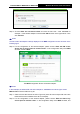
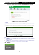
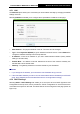

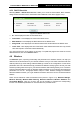
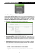
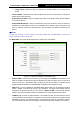
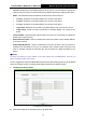
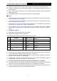
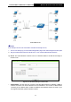
Table Of Contents
- 组合 4.pdf
- 组合 2.pdf
- TL-WA801ND UG.pdf
- Package Contents
- Chapter 1 Introduction
- Chapter 2 Hardware Installation
- Chapter 3 Quick Installation Guide
- Chapter 4 Configure the Device
- Appendix A: Application Example
- Appendix B: Factory Defaults
- Appendix C: Troubleshooting
- Appendix D: Specifications
- Appendix E: Glossary
- RF Exposure Information
- TL-WA801ND UG.pdf
- RF Exposure Information
- 组合 2.pdf
- TL-WA801ND IC UG
- 组合 2
- TL-WA801ND UG.pdf
- Package Contents
- Chapter 1 Introduction
- Chapter 2 Hardware Installation
- Chapter 3 Quick Installation Guide
- Chapter 4 Configure the Device
- Appendix A: Application Example
- Appendix B: Factory Defaults
- Appendix C: Troubleshooting
- Appendix D: Specifications
- Appendix E: Glossary
- RF Exposure Information
- TL-WA801ND UG.pdf
- TL-WA801ND UG.pdf
- Package Contents
- Chapter 1 Introduction
- Chapter 2 Hardware Installation
- Chapter 3 Quick Installation Guide
- Chapter 4 Configure the Device
- Appendix A: Application Example
- Appendix B: Factory Defaults
- Appendix C: Troubleshooting
- Appendix D: Specifications
- Appendix E: Glossary
- 组合 2
TL-WA701ND/TL-WA801ND/TL-WA901ND
Wireless N Access Point User Guide
31
Select the checkbox before Enable VLAN to enable VLAN function for this access point.
Configure the SSID and its corresponding VLAN ID. The detailed parameters are shown as
the above figure.
STA1, STA2, STA3 and STA4 join to the wireless network with SSID1, SSID2, SSID3 and
SSID4 respectively.
Click Save to apply the current security settings for the selected SSID.
Note:
1. The wireless STAs join to the network with different VLAN IDs cannot communicate with each
other, for example, STA1 and STA2.
2. The wireless STAs join to the network with the same VLAN ID can communicate with each
other, for example, STA1 and STA3.
3. All wireless STAs can log on to the Web management page of TL-WA901ND and manage the
access point, for example, STA1, STA2, STA3 and STA4.
4. All the packets received in the wired network from the wireless STA will be added a
corresponding VLAN Tag of the wireless STA, unless the VLAN ID of the wireless network is
set to 1.
2. Configure the Switch.
Enable 802.1Q Tag VLAN function on the switch.
Make sure the Untag frames are forwarded.
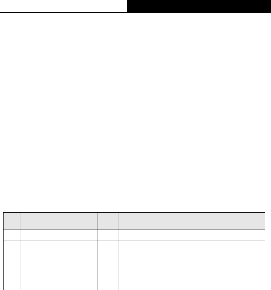
The following table shows the detailed configuration for the switch
Port VLAN ID PVID Egress Rule
Processing mode of Utag
Frames
1 1 1 Untag
Forwarding
2 2 2 Untag
Forwarding
3 3 3 Untag
Forwarding
4 4 4 Untag
Forwarding
5
Port5 belongs to all
VLANs
1 Tag
Forwarding
Table 4-1 Configure the Tag VLAN Switch
Connect PC1, PC2, PC3 and PC4 to port1, port2, port3 and port4 of the switch respectively.
The corresponding VLAN IDs of the four ports are 1, 2, 3 and 4.
Configure port5 of the switch to be the member of VLAN1, VLAN2, VLAN3 and VLAN4 and
connect it to the LAN port of TL-WA901ND.
Configure the VLAN ID of the PC that can log on to the Web management page of
TL-WA901ND via the LAN port equal to the PVID of port 5.
3. Verify the communication status after the above configuration is completed.
If VLAN ID of the PC connected to the switch is different from the VLAN ID of the wireless
STA, the two cannot communicate with each other, for example, PC1 and STA2.
If the PC connected to the switch and the wireless STA have the same VLAN ID, the two can
communicate with each other, for example PC2 and STA2.