User Guide 450Mbps/300Mbps Wireless N Access Point TL-WA901ND/TL-WA801ND REV3.0.
Contents Chapter 1. About This Guide . . . . . . . . . . . . . . . . . . . . . . . . . . . . . . . . . . . . . . . . .1 Chapter 2. Get to Know About Your Access Point . . . . . . . . . . . . . . . . . . . . . 2 1. 1. 1. 2. Product Overview. . . . . . . . . . . . . . . . . . . . . . . . . . . . . . . . . . . . . . . . . . . . . . . . . . . . . . . . . . . . 3 Panel Layout. . . . . . . . . . . . . . . . . . . . . . . . . . . . . . . . . . . . . . . . . . . . . . . . . . . . . . . . . . . . . . . . . 3 1. 2.
4. 4. 2.Wireless Security . . . . . . . . . . . . . . . . . . . . . . . . . . . . . . . . . . . . . . . . . . . . . . . . . . . . 32 4. 4. 3.Wireless MAC Filtering . . . . . . . . . . . . . . . . . . . . . . . . . . . . . . . . . . . . . . . . . . . . . . . 42 4. 4. 4.Wireless Advanced . . . . . . . . . . . . . . . . . . . . . . . . . . . . . . . . . . . . . . . . . . . . . . . . . . . 44 4. 4. 5.Wireless Statistics . . . . . . . . . . . . . . . . . . . . . . . . . . . . . . . . . . . . . . . . . . . . . .
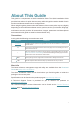
About This Guide This guide is a complement to Quick Installation Guide. The Quick Installation Guide provides instructions for quick Internet setup, while this guide contains details of each function and demonstrates how to configure them. When using this guide, please notice that features of the access point may vary slightly depending on the model and software version you have, and on your location, language, and Internet service provider.
Chapter 1 Get to Know About Your Access Point This chapter introduces what the access point can do and shows its appearance.
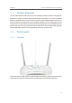
Chapter 1 1. 1. Get to Know About Your Access Point Product Overview The TP-LINK Wireless N Access Point, with multiple operation modes, is designed to establish or expand a scalable high-speed wireless N network or to connect multiple Ethernet enabled devices such as game consoles, digital media adapters, printers, or network attached storage devices to a wireless network. The AP supports a host of dierent functions that makes your wireless networking experience more exible than ever before.
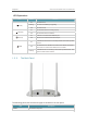
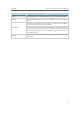
Chapter 1 Get to Know About Your Access Point LED Explanation Name Status On (Power) (Wireless) (Ethernet) Flashing The device is initializing or upgrading. The device is off. On The wireless function is working properly. Off The wireless function is disabled. On A device is connected to the Ethernet port. Off No device is connected to the Ethernet port. Off Flashing 1. 2. 2. The device is on.
Chapter 1 Get to Know About Your Access Point Item Description Power For connecting the access point to a power socket via the provided power adapter. Ethernet One LAN 10/100Mbps RJ45 port connects to a network device, such as a switch or a router. Press and hold this button until SYS LED becomes quick-flash from slow-flash to reset the access point to its factory default settings.
Chapter 2 Connect the Hardware This chapter contains the following sections: • Position Your Access Point • Connect Your Access Point
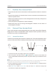
$POOFDU UIF )BSEXBSF Chapter 2 2. 1. Position Your Access Point • The product should not be located where it will be exposed to moisture or excessive heat. • Place the access point in a location where it can be connected to various devices as well as to a power source. • Make sure the cables and power cord are safely placed out of the way so they do not create a tripping hazard. • The access point can be placed on a shelf or desktop.
$POOFDU UIF )BSEXBSF Chapter 2 5. Now, reconnect your wireless devices to the new Wi-Fi network. 2. 2. 2. Repeater (Range Extender) Mode Extends the range of an existing Wi-Fi network. This mode is suitable if you are in a Wi-Fi dead-zone or a place with weak wireless signal, and you want to have a greater effective range of the wireless signal throughout your home or office. Internet Host AP’s SSID Host AP’s SSID A B 1. Connect the AP device according to steps A and B in the diagram. 2.
$POOFDU UIF )BSEXBSF Chapter 2 1. Connect the AP device according to steps A and B in the diagram. 2. Turn on the power, wait until the Power ( ) and Wireless ( ) LEDs are lit and stable, and use the default SSID and Password printed on the product label to join the AP device’s Wi-Fi network. 3. Launch a web browser and enter http://tplinkap.net. Then log in using admin (all lowercase) for both Username and Password. 4. Click Quick Setup, select Bridge with AP mode and click Next.
$POOFDU UIF )BSEXBSF Chapter 2 VLAN 1 Internet TL-WA901ND’s SSID Wired Router VLAN 2 B D C A 1. Connect the AP device according to steps A to D in the diagram. 2. Turn on the power, wait until the Power ( ) and Wireless ( ) LEDs are lit and stable, and use the default SSID and Password printed on the product label to join the AP device’s Wi-Fi network. 3. Launch a web browser and enter http://tplinkap.net. Then log in using admin (all lowercase) for both Username and Password. 4.
Chapter 3 Set Up Internet Connection Via Quick Setup Wizard This chapter introduces how to connect your access point to the Internet via the webbased Quick Setup Wizard.
Chapter 3 3. 1. Set Up Internet Connection Via Quick Setup Wizard Log in to the Access Point With a Web-based utility, it is easy to configure and manage the access point. The Webbased utility can be used on any Windows, Macintosh or UNIX OS with a Web browser, such as Microsoft Internet Explorer, Mozilla Firefox or Apple Safari. Follow the steps below to log into your access point. 1. Visit http://tplinkap.net, and log in using admin (all lowercase) for both Username and Password.
Chapter 3 Set Up Internet Connection Via Quick Setup Wizard 2. Select the LAN IP type of the access point or leave the default setting Smart IP for most cases, and then click Next. 3. Click Finish to complete the configuration. Reconnect your wireless devices to the new Wi-Fi network.
Chapter 3 3. 2. 2. Set Up Internet Connection Via Quick Setup Wizard Repeater (Range Extender) Mode 1. Click Survey to find your host network and click Connect. Enter the host network’s password in the Wireless Password field, and then click Next. 2. Select the LAN IP type of the access point or leave the default setting Smart IP for most cases, and then click Next. 3. Click Finish to complete the configuration.
Chapter 3 Set Up Internet Connection Via Quick Setup Wizard 4. Relocate the access point about halfway between your host AP and the Wi-Fi dead zone. The extended network shares the same network name and password as your host network. 3. 2. 3. Bridge with AP Mode 1. Click Survey to find your host network, enter the host network’s password in the Wireless Password field.
Chapter 3 Set Up Internet Connection Via Quick Setup Wizard 2. Select the LAN IP type of the access point or leave the default setting Smart IP for most cases, and then click Next. 3. Click Finish to complete the configuration. 4. Relocate the access point to a good place. Connect your wireless devices to the Wi-Fi network using the AP’s SSID and password.
Chapter 3 3. 2. 4. Set Up Internet Connection Via Quick Setup Wizard Client Mode 1. Click Survey to find your host network and click Connect. Enter the host network’s password in the Wireless Password field, and then click Next. 2. Select the LAN IP type of the access point or leave the default setting Smart IP for most cases, and then click Next. 3. Click Finish to complete the configuration. Now your wired connected devices can enjoy the Internet surfing.
Chapter 3 3. 2. 5. Set Up Internet Connection Via Quick Setup Wizard Multi-SSID Mode 1. Enable the VLAN function and check SSIDs you want to enable. Customize the SSIDs and the passwords according to your needs and click Next. 2. Select the LAN IP type of the access point or leave the default setting Smart IP for most cases, and then click Next.
Chapter 3 Set Up Internet Connection Via Quick Setup Wizard 3. Click Finish to complete the configuration. 4. Connect your wireless devices to the different Wi-Fi networks to be isolated by VLANs.
Chapter 4 This chapter presents how to configure the various features of your Access Point.
Chapter 4 4. 1. Status 1. Visit http://tplinkap.net, and log in using admin (all lowercase) for both Username and Password. 2. Go to Status. You can view the current status information of the access point. • Firmware Version - The version information of the access point’s firmware. • Hardware Version - The version information of the access point’s hardware. • Wired - This field displays the current settings of the LAN, and you can configure them on the Network > LAN page.
Chapter 4 • MAC Address - The physical address of the access point. • Traffic Statistics - The access point’s traffic stastics. • Received (Bytes) - Traffic in bytes received from the ETHERNET port. • Received (Packets) - Traffic in packets received from the ETHERNET port. • Sent (Bytes) - Traffic in bytes sent out from the ETHERNET port. • Sent (Packets) - Traffic in packets sent out from the ETHERNET port.
Chapter 4 3. Within two minutes, press the WPS button on your client device. 4. A success message will appear on the WPS page if the client device has been successfully added to the access point’s network. Method TWO: Enter the Client’s PIN 1. Keep the WPS Status as Enabled and click Add Device. 2. Select Enter the new device’s PIN, enter your client device’s current PIN in the PIN filed and click Connect. 3.
Chapter 4 4. 3. Network 4. 3. 1. LAN 1. Visit http://tplinkap.net, and log in using admin (all lowercase) for both Username and Password. 2. Go to Network > LAN. 3. Configure the IP parameters of the LAN and click Save. • MAC Address - The physical address of the LAN ports. The value can not be changed. • Type - Either select Smart IP(DHCP) to get IP address from DHCP server, or Static IP to configure IP address manually.
Chapter 4 • DHCP Server - Enable or disable the DHCP server. If disabled, you must have another DHCP server within your network or else you must configure the computer manually. • Start IP Address - Specify an IP address for the DHCP Server to start with when assigning IP addresses. 192.168.0.100 is the default start address. • End IP Address - Specify an IP address for the DHCP Server to end with when assigning IP addresses. 192.168.0.199 is the default end address.
Chapter 4 4. 3. 3. DHCP Client List 1. Visit http://tplinkap.net, and log in using admin (all lowercase) for both Username and Password. 2. Go to DHCP > DHCP Client List to view the information of the clients connected to the access point. • Client Name - The name of the DHCP client. • MAC Address - The MAC address of the DHCP client. • Assigned IP - The IP address that the access point has allocated to the DHCP client. • Lease Time - The time of the DHCP client leased.
Chapter 4 • Wireless Network Name - Identifies your wireless network name. Create a name up to 32 characters and make sure all wireless points in the wireless network with the same SSID. The default SSID is TP-LINK_AP_XXXX (XXXX indicates the last unique four characters of each device’s MAC address). This value is case-sensitive. For example, TEST is NOT the same as test. • Channel - Determines the operating frequency to be used.
Chapter 4 • Enable VLAN - Check this box and then you can change the VLAN ID of each SSID. If you want to configure the Guest and Internal networks on VLAN, the switch you are using must support VLAN. As a prerequisite step, configure a port on the switch for handling VLAN tagged packets as described in the IEEE802.1Q standard, and enable this field. • SSID (1-4) - Up to four SSIDs for each BSS (Basic Service Set) can be entered in the filed SSID1 ~ SSID4.
Chapter 4 Client Mode • Enable WDS - The AP client can connect to AP with WDS enabled or disabled. If WDS is enabled, all traffic from wired networks will be forwarded in the format of WDS frames consisting of four address fields. If WDS is disabled, three address frames are used. If your AP supports WDS well, please enable this option. • Wireless Name of Root AP - If you select the radio button before Wireless Name of Root AP, the AP client will connect to the AP according to SSID.
Chapter 4 • MAC Address of Root AP - If you select the radio button before MAC Address of Root AP, the AP client will connect to the AP according MAC address. Enter the MAC address of AP that you want to access. • Mode - Select the desired wireless mode. The options are: • 11b only - Only 802.11b wireless stations can connect to the device. • 11g only - Only 802.11g wireless stations can connect to the device. • 11n only - Only 802.11n wireless stations can connect to the device.
Chapter 4 • 11n only - Only 802.11n wireless stations can connect to the device. • 11bg mixed - Both 802.11b and 802.11g wireless stations can connect to the device. • 11bgn mixed - All 802.11b, 802.11g and 802.11n wireless stations can connect to the device. • Channel Width - Determines the channel width to be used. It is unnecessary to change the default value unless required.
Chapter 4 • Key type - This option should be chosen according to the AP’s security configuration. It is recommended that the security type is the same as your AP’s security type. • Password - If the Remote AP that your device is going to connect needs password, you need to fill the password in this blank. Local Wireless AP Setting • Local Wireless Name - Name for the AP. • Mode - This field determines the wireless mode which the device works on. • 11b only - Only 802.
Chapter 4 Access Point • Disable Security - Check this box radio button to disable wireless security. If disabled, the wireless stations will be able to connect this device without encryption. It is strongly recommended that you choose one of the security types to enable security. • WPA/WPA2-Personal(Recommended) - Select WPA/WPA2 based on Radius Server. • Version - You can select one of following versions.
Chapter 4 • Encryption - You can select either Automatic, TKIP or AES. • Radius Server IP - Enter the IP address of the Radius Server. • Radius Port - Enter the port used by radius service. • Radius Password - Enter the password for the Radius Server. • Group Key Update Period - Specify the group key update interval in seconds. The value can be either 0 or at least 30. Enter 0 to disable the update. • WEP - Select 802.11 WEP security.
Chapter 4 Multi-SSID You can choose which SSID to configure wireless security settings for in the blank behind Operation Mode. • Disable Security - Check this box radio button to disable wireless security. If disabled, the wireless stations will be able to connect this device without encryption. It is strongly recommended that you choose one of the security types to enable security. • WPA/WPA2-Personal (Recommended) - Select WPA/WPA2 based on Radius Server.
Chapter 4 • Automatic - Select WPA or WPA2 automatically based on the wireless station’s capability and request. • WPA - Wi-Fi Protected Access. • WPA2 - WPA version 2. • Encryption - You can select either Automatic, TKIP or AES. • Radius Server IP - Enter the IP address of the Radius Server. • Radius Port - Enter the port used by radius service. • Radius Password - Enter the password for the Radius Server.
Chapter 4 • WPA2-PSK - Pre-shared key of WPA2. • Encryption - You can select either Automatic(Recommended), TKIP or AES. • Wireless Password - You can enter ASCII or Hexadecimal characters. For Hexadecimal, the length should be between 8 and 64 characters; for ASCII, the length should be between 8 and 63 characters. • Group Key Update Period - Specify the group key update interval in seconds. The value can be either 0 or at least 30. Enter 0 to disable the update.
Chapter 4 WDS Repeater • Disable Security - Check this box radio button to disable wireless security. If disabled, the wireless stations will be able to connect this device without encryption. It is strongly recommended that you choose one of the security types to enable security. • WPA/WPA2-Personal (Recommended) - Select WPA/WPA2 based on Radius Server. • Version - You can select one of following versions.
Chapter 4 • WEP Key Format - You can select ASCII or Hexadecimal format. ASCII format stands for any combination of keyboard characters in the specified length. Hexadecimal format stands for any combination of hexadecimal digits (0-9, a-f, A-F) in the specified length. • WEP Key - Select which of the four keys will be used and enter the matching WEP key information for your network in the selected key radio button.
Chapter 4 • WPA/WPA2-Personal (Recommended) - Select WPA/WPA2 based on Radius Server. • Version - You can select one of following versions. • Automatic (Recommended) - Select WPA-Personal or WPA2-Personal automatically based on the wireless station’s capability and request. • WPA-PSK - Pre-shared key of WPA. • WPA2-PSK - Pre-shared key of WPA2. • Encryption - You can select either Automatic(Recommended), TKIP or AES.
Chapter 4 Bridge with AP • Disable Security - Check this box radio button to disable wireless security. If disabled, the wireless stations will be able to connect this device without encryption. It is strongly recommended that you choose one of the security types to enable security. • WPA/WPA2-Personal(Recommended) - Select WPA/WPA2 based on Radius Server. • Version - You can select one of following versions.
Chapter 4 • Radius Server IP - Enter the IP address of the Radius Server. • Radius Port - Enter the port used by radius service. • Radius Password - Enter the password for the Radius Server. • Group Key Update Period - Specify the group key update interval in seconds. The value can be either 0 or at least 30. Enter 0 to disable the update. • WEP - Select 802.11 WEP security. • Type - You can select one of following types.
Chapter 4 I want to: Deny or allow specific wireless client devices to access my network by their MAC addresses. For example, you want the wireless client A with the MAC address 00-0A-EB-B0-00-0B and the wireless client B with the MAC address 00-0A-EB-00-07-5F to access the access point, but other wireless clients cannot access the access point. 1. Visit http://tplinkap.net, and log in using admin (all lowercase) for both Username and Password. 2.
Chapter 4 4. 4. 4. Wireless Advanced The configuration for each operation mode is almost the same, we take Access Point mode for example here. 1. Visit http://tplinkap.net, and log in using admin (all lowercase) for both Username and Password. 2. Go to Wireless > Wireless Advanced. 3. Configure the advanced settings of your wireless network and click Save.
Chapter 4 Beacon Intervals. The default value is 1, which indicates the DTIM Interval is the same as Beacon Interval. • Enable WMM - WMM function can guarantee the packets with high-priority messages being transmitted preferentially. It is strongly recommended to enable this function. • Enable Short GI - It is recommended to enable this function, for it will increase the data capacity by reducing the guard interval time.
Chapter 4 • Rate - The Throughput unit. • Run Time - How long this function is running. • Transmit - Wireless transmit rate information. • Receive - Wireless receive rate information. Click Start/Stop to start or stop wireless throughput monitor. 4. 5. System Tools 4. 5. 1. SNMP Simple Network Management Protocol (SNMP) is a popular network monitoring and management protocol. 1. Visit http://tplinkap.net, and log in using admin (all lowercase) for both Username and Password. 2.
Chapter 4 • SNMP Agent - Select the radio button before Enable will enable this function if you want to have remote control through SNMPv1/v2 agent with MIB-II. Select the radio button before Disable will disable this function. The default setting is Disable. • SysContact - The textual identification of the contact person for this managed node. • SysName - An administratively-assigned name for this managed node. • SysLocation - The physical location of this node.
Chapter 4 • Diagnostic Tool - Select one diagnostic tool. • Ping - This diagnostic tool troubleshoots connectivity, reachability, and name resolution to a given host or gateway. • Tracerouter - This diagnostic tool tests the performance of a connection. Note: You can use ping/traceroute to test both numeric IP address or domain name. If pinging/tracerouting the IP address is successful, but pinging/tracerouting the domain name is not, you might have a name resolution problem.
Chapter 4 Note: Only one user can use this tool at one time. Options “Number of Pings”, “Ping Size” and “Ping Timeout” are used for the Ping function. Option “Tracert Hops” is used for the Tracert function. 4. 5. 3. Ping Watch Dog The Ping Watch Dog is dedicated for continuous monitoring of the particular connection to remote host using the Ping tool. It makes the access point continuously ping a user defined IP address (it can be the Internet gateway for example).
Chapter 4 4. 5. 4. Firmware Upgrade TP-LINK is dedicated to improving and richening the product features, giving users a better network experience. We will release the latest firmware at TP-LINK official website. You can download the latest firmware file from the Support page of our website www.tp-link.com and upgrade the firmware to the latest version. 1. Download the latest firmware file for the access point from our website www.tp-link.com. 2. Visit http://tplinkap.
Chapter 4 • To backup configuration settings: Click Backup to save a copy of the current settings in your local computer. A “.bin“ file of the current settings will be stored in your computer. • To restore configuration settings: 1. Click Choose File to locate the backup configuration file stored in your computer, and click Restore. 2. Wait a few minutes for the restoring and rebooting. Note: During the restoring process, do not power off or reset the access point. 4. 5. 7.
Chapter 4 It is strongly recommended that you change the default username and password of the access point, for all users that try to access the access point’s web-based utility or Quick Setup will be prompted for the access point’s username and password. Note: The new username and password must not exceed 15 characters and not include any spacing. 3. Click Save. 4. 5. 9. System Log 1. Visit http://tplinkap.net, and log in using admin (all lowercase) for both Username and Password.
Chapter 4 • From - Your mail box address. The access point will connect it to send logs. • To - Recipient’s mail address. The destination mailbox which will receive logs. • SMTP Server - Your smtp server. It corresponds with the mailbox filled in the From field. You can log on the relevant website for help if you are not clear with the address. • Authentication - Most SMTP Server requires Authentication.
Chapter 4 • Save Log - Click to save all the logs in a txt file. • Mail Log - Click to send an email of current logs manually according to the address and validation information set in Mail Settings. • Clear Log - All the logs will be deleted from the access point permanently, not just from the page. Click Next to go to the next page, or click Previous to return to the previous page. 4. 6.
FAQ Q1. How do I restore my Access Point’s configuration to its factory default settings? With the device powered on, use a pin to press and hold the Reset button until the Power LED starts blinking, then release the button. Note: Upon resetting, all previous configurations will be cleared, and the AP device will reset to the default Access Point Mode. Q2. What can I do if I forgot my wireless password? The default wireless password is printed on the label of the access point.
• The Best Way is Halfway Generally, the ideal location for the repeater is about halfway between your wireless router and your wireless clients and make sure that the location you choose is within the range of the host router. If that is not possible, place it closer to your wireless router to ensure stable performance. • Less Obstacles Ensure Better Performance Choose a location with less obstacles that may block the signal between the AP device and the host network.
COPYRIGHT & TRADEMARKS Specifications are subject to change without notice. is a registered trademark of TP-LINK TECHNOLOGIES CO., LTD. Other brands and product names are trademarks or registered trademarks of their respective holders. No part of the specifications may be reproduced in any form or by any means or used to make any derivative such as translation, transformation, or adaptation without permission from TP-LINK TECHNOLOGIES CO., LTD. Copyright © 2016 TP-LINK TECHNOLOGIES CO., LTD.
FCC STATEMENT This equipment has been tested and found to comply with the limits for a Class B digital device, pursuant to part 15 of the FCC Rules. These limits are designed to provide reasonable protection against harmful interference in a residential installation. This equipment generates, uses and can radiate radio frequency energy and, if not installed and used in accordance with the instructions, may cause harmful interference to radio communications.
CE Mark Warning This is a class B product. In a domestic environment, this product may cause radio interference, in which case the user may be required to take adequate measures. RF Exposure Information This device meets the EU requirements (1999/5/EC Article 3.1a) on the limitation of exposure of the general public to electromagnetic fields by way of health protection. The device complies with RF specifications when the device used at 20 cm from your body.
Déclaration d'exposition aux radiations: Cet équipement est conforme aux limites d'exposition aux rayonnements IC établies pour un environnement non contrôlé. Cet équipement doit être installé et utilisé avec un minimum de 20 cm de distance entre la source de rayonnement et votre corps. Industry Canada Statement CAN ICES-3 (B)/NMB-3(B) Korea Warning Statements . NCC Notice !" #$!%&'()*+,-.
When product has power button, the power button is one of the way to shut off the product; when there is no power button, the only way to completely shut off power is to disconnect the product or the power adapter from the power source. Don’t disassemble the product, or make repairs yourself. You run the risk of electric shock and voiding the limited warranty. If you need service, please contact us. Avoid water and wet locations.