TL-WR841N User Guide 300Mbps Wireless N Router REV12.0.
Contents About This Guide ...............................................................................................1 Chapter 1. Get to Know About Your Router . . . . . . . . . . . . . . . . . . . . . . . . . 2 1. 1. 1. 2. Product Overview . . . . . . . . . . . . . . . . . . . . . . . . . . . . . . . . . . . . . . . . . . . . . . . . . . . . . . . . . . 3 Panel Layout . . . . . . . . . . . . . . . . . . . . . . . . . . . . . . . . . . . . . . . . . . . . . . . . . . . . . . . . . . . . . . . 3 1. 2.
4. 7. 4. 6. 3.Address Reservation . . . . . . . . . . . . . . . . . . . . . . . . . . . . . . . . . . . . . . . . . . . . . . . . 36 Forwarding . . . . . . . . . . . . . . . . . . . . . . . . . . . . . . . . . . . . . . . . . . . . . . . . . . . . . . . . . . . . . . . 37 4. 7. 1.Virtual Servers . . . . . . . . . . . . . . . . . . . . . . . . . . . . . . . . . . . . . . . . . . . . . . . . . . . . . . 37 4. 7. 2.Port Triggering . . . . . . . . . . . . . . . . . . . . . . . . . . . . . . . . . . . . . . . .
. 17. Logout. . . . . . . . . . . . . . . . . . . . . . . . . . . . . . . . . . . . . . . . . . . . . . . . . . . . . . . . . . . . . . . . . . . . 72 FAQ .....................................................................................................................
About This Guide This guide is a complementation of Quick Installation Guide. The Quick Installation Guide instructs you on quick Internet setup, and this guide provides details of each function and shows you the way to configure these functions appropriate to your needs. When using this guide, please notice that features of the router may vary slightly depending on the model and software version you have, and on your location, language, and Internet service provider.
Chapter 1 Get to Know About Your Router This chapter introduces what the router can do and shows its appearance.
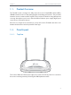
Chapter 1 1. 1. Get to Know About Your Router Product Overview The TP-LINK router is designed to fully meet the need of Small Office/Home Office (SOHO) networks and users demanding higher networking performance. The powerful antennas ensure continuous Wi-Fi signal to all your devices while boosting widespread coverage throughout your home, and the built-in Ethernet ports supply high-speed connection to your wired devices.
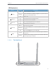
Chapter 1 Get to Know About Your Router LED Explanation Name Status Indication On (Power) (Wireless) (Ethernet) System initialization completes. System initialization or firmware upgrade is in process. Do not disconnect or power off the router. Flashing Off Power is off. On The wireless function is working properly. Off The wireless function is disabled. On The corresponding Ethernet port is connected. Off No Ethernet port is connected. The Internet is available.
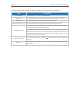
Chapter 1 Get to Know About Your Router The following parts (view from left to right) are located on the rear panel. Item ON/OFF Button Description Press this button to power on or off the router. Power Port For connecting the router to a power socket via the provided power adapter. WAN Port For connecting to a DSL/Cable modem, or an Ethernet port. Ethernet Ports (1/2/3/4) For connecting your PCs or other wired network devices to the router.
Chapter 2 Connect the Hardware This chapter contains the following sections: • Position Your Router • Connect Your Router
Chapter 2 2. 1. Connect the Hardware Position Your Router • The product should not be located in a place where it will be exposed to moisture or excessive heat. • Place the router in a location where it can be connected to multiple devices as well as to a power source. • Make sure the cables and power cord are safely placed out of the way so they do not create a tripping hazard. • The router can be placed on a shelf or desktop.
Chapter 2 Connect the Hardware 5 ) Verify that the hardware connection is correct by checking these LEDs. Power On Wi-Fi On Internet On Tips: If Wi-Fi LED is off, press and hold the WPS/Wi-Fi button until it is on. 2. Connect your computer to the router. • Method 1: Wired Turn off the Wi-Fi on your computer and connect the devices as shown below. Ethernet cable 1 2 3 4 WPS/ RESET WIFI ON/OFF • Method 2: Wirelessly 1.
Chapter 2 Connect the Hardware Close to ON/OFF POWER WAN 1 2 3 4 WPS/ RESET WIFI ON/OFF 9
Chapter 3 Set Up Internet Connection Via Quick Setup Wizard This chapter introduces how to connect your router to the Internet via the web-based Quick Setup Wizard.
Chapter 3 3. 1. Set Up Internet Connection Via Quick Setup Wizard Log into the Router With the web-based utility, it is easy to configure and manage the router. The webbased utility can be used on any Windows, Macintosh or UNIX OS with a Web browser, such as Microsoft the Internet Explorer, Mozilla Firefox or Apple Safari. Follow the steps below to log in to your router. 1. Set up the TCP/IP Protocol in Obtain an IP address automatically mode on your computer. 2. Visit http://tplinkwifi.
Chapter 3 Set Up Internet Connection Via Quick Setup Wizard 2. In this case, we take dynamic IP for instance. Please select to clone the mac address or not and click Next. For other connection types, please enter the parameters provided by your ISP, and then click Next. 3. Either customize your Wireless Network Name and Wireless Password or keep the default ones, and then click Next. 4. Click Finish to complete the configuration.
Chapter 3 Set Up Internet Connection Via Quick Setup Wizard 13
Chapter 4 Configure This chapter presents how to configure the various features of the router.
Chapter 4 4. 1. Configure Status 1. Visit http://tplinkwifi.net, and log in with the username and password you set for the router. 2. Go to Status. You can view the current status information of the router. • Firmware Version - The version information of the router’s firmware. • Hardware Version - The version information of the router’s hardware. • LAN - This field displays the current settings of the LAN, and you can configure them on the Network > LAN page.
Chapter 4 Configure • Wireless - This field displays the basic information or status of the wireless function, and you can configure them on the Wireless > Wireless Settings page. • Wireless Radio - Indicates whether the wireless feature is enabled or not. • Name (SSID) - The SSID of the router. • Mode - The current wireless working mode in use. • Channel Width - The current wireless channel width in use. • Channel - The current wireless channel in use.
Chapter 4 Configure 2. Go to WPS. 3. Follow one of the following three methods to connect your client device to the router’s Wi-Fi network. Method ONE: Press the WPS Button on Your Client Device 1. Keep the WPS Status as Enabled and click Add Device. 2. Select Press the button of the new device in two minutes and click Connect. 3. Within two minutes, press the WPS button on your client device. 4.
Chapter 4 Configure 3. A success message will appear on the WPS page if the client device has been successfully added to the router’s network. Method Three: Enter the Router’s PIN 1. Keep the WPS Status as Enabled and get the Current PIN of the router. 2. Enter the router’s current PIN on your client device to join the router’s Wi-Fi network. 4. 3. Network 4. 3. 1. WAN 1. Visit http://tplinkwifi.net, and log in with the username and password you set for the router. 2. Go to Network > WAN. 3.
Chapter 4 Configure • MTU Size - The normal MTU (Maximum Transmission Unit) value for most Ethernet networks is 1500 Bytes. It is not recommended that you change the default MTU size unless required by your ISP. • Use These DNS Servers - If your ISP providess you one or two DNS addresses, select Use These DNS Servers and enter the primary and secondary addresses. Otherwise, the DNS servers will be assigned dynamically from your ISP. • Host Name - This option specifies the name of the router.
Chapter 4 Configure • Subnet Mask - Enter the subnet mask in dotted-decimal notation provided by your ISP. Normally 255.255.255.0 is used as the subnet mask. • Default Gateway - Enter the gateway IP address in dotted-decimal notation provided by your ISP. • MTU Size - The normal MTU (Maximum Transmission Unit) value for most Ethernet networks is 1500 Bytes. It is not recommended that you change the default MTU size unless required by your ISP.
Chapter 4 Configure field. Otherwise, enter the number of minutes you want to have elapsed before your Internet access disconnects. • Connect Automatically - The connection can be re-established automatically when it is down. • Time-based Connecting - The connection will only be established in the period from the start time to the end time (both are in HH:MM format). • Connect Manually - You can click Connect/Disconnect to connect/disconnect immediately.
Chapter 4 Configure • Detect Online Interval - The router will detect Access Concentrator online at every interval. The default value is 0. You can input the value between 0 and 120. The value 0 means no detect. • Primary DNS/Secondary DNS - If your ISP does not automatically assign DNS addresses to the router, please select Use the following DNS servers and enter the IP address in dotted-decimal notation of your ISP’s primary DNS server. If a secondary DNS server address is available, enter it as well.
Chapter 4 Configure • Connect Automatically - The connection can be re-established automatically when it is down. • Connect Manually - You can click Connect/Disconnect to connect/disconnect immediately. This mode also supports the Max Idle Time function as Connect on Demand mode. The Internet connection can be disconnected automatically after a specified inactivity period (Max Idle Time) and not be able to re-establish when you attempt to access the Internet again.
Chapter 4 Configure • Dynamic IP/ Static IP - Select either as required by your ISP. If Static IP is selected, please enter the IP address, subnet marsk, gateway and DNS also provided by your ISP. • Internet IP Address/ Internet DNS - The Internet IP address and DNS server address assigned by L2TP server.
Chapter 4 Configure • User Name/Password - Enter the user name and password provided by your ISP. These fields are case-sensitive. • Confirm Password - Enter the Password provided by your ISP again to ensure the password you entered is correct. • Connect/Disconnect - Click this button to connect or disconnect immediately. • Dynamic IP/ Static IP - Select either as required by your ISP. If Static IP is selected, please enter the IP address, subnet marsk, gateway and DNS also provided by your ISP.
Chapter 4 Configure • Connect Automatically - The connection can be re-established automatically when it is down. • Connect Manually - You can click Connect/Disconnect to connect/disconnect immediately. This mode also supports the Max Idle Time function as Connect on Demand mode. The Internet connection can be disconnected automatically after a specified inactivity period (Max Idle Time) and not be able to re-establish when you attempt to access the Internet again.
Chapter 4 Configure • MAC Address - The physical address of the LAN ports. The value can not be changed. • IP Address - Enter the IP address in dotted-decimal notation of your router (factory default - 192.168.0.254). • Subnet Mask - An address code that determines the size of the network. Normally 255.255.255.0 is used as the subnet mask. • IGMP Proxy - The Internet Group Management Protocol (IGMP) feature allow you to watch TV on IPTV-supported devices on the LAN .
Chapter 4 Configure address). It is strongly recommended that you change your network name (SSID). This value is case-sensitive. For example, TEST is NOT the same as test. • Mode - Select the desired mode. It is strongly recommended that you keep the default setting 11bgn mixed, so that all 802.11b/g/n wireless devices can connect to the router. Note: If 11bg mixed mode is selected, the Channel Width field will turn grey and the value will become 20M, and cannot be changed.
Chapter 4 Configure • Key type - This option should be chosen according to the AP’s security configuration. It is recommended that the security type is the same as your AP’s security type. • WEP Index - This option should be chosen if the key type is WEP (ASCII) or WEP (HEX). It indicates the index of the WEP key. • Auth Type - This option should be chosen if the key type is WEP (ASCII) or WEP (HEX). It indicates the authorization type of the Root AP.
Chapter 4 Configure • Version - Select Automatic, WPA-PSK or WPA2-PSK. • Encryption - Select Automatic, TKIP or AES. • Wireless Password - Enter ASCII or Hexadecimal characters. For Hexadecimal, the length should be between 8 and 64 characters; for ASCII, the length should be between 8 and 63 characters. • Group Key Update Period - Specify the group key update interval in seconds. The value can be 0 or at least 30. Enter 0 to disable the update.
Chapter 4 4. 4. 3. Configure Wireless MAC Filtering Wireless MAC Filtering is used to deny or allow specific wireless client devices to access your network by their MAC addresses. I want to: Deny or allow specific wireless client devices to access my network by their MAC addresses. For example, you want the wireless client A with the MAC address 00-0A-EB-B0-00-0B and the wireless client B with the MAC address 00-0A-EB-00-07-5F to access the router, but other wireless clients cannot access the router.
Chapter 4 Done! 4. 4. 4. Configure Now only client A and client B can access your network. Wireless Advanced 1. Visit http://tplinkwifi.net, and log in with the username and password you set for the router. 2. Go to Wireless > Wireless Advanced. 3. Configure the advanced settings of your wireless network and click Save.
Chapter 4 Configure DTIM Interval value. You can specify the value between 1-255 Beacon Intervals. The default value is 1, which indicates the DTIM Interval is the same as Beacon Interval. • Enable WMM - WMM function can guarantee the packets with high-priority messages being transmitted preferentially. It is strongly recommended to enable this function. • Enable Short GI - It is recommended to enable this function, for it will increase the data capacity by reducing the guard interval time.
Chapter 4 Configure 1. Visit http://tplinkwifi.net, and log in with the username and password you set for the router. 2. Go to Guest Network > Wireless Settings. 3. Enable the Guset Network function. 4. Create a network name for your guest network. 5. Select the Wireless Security type and create the Password of the guest network. 6. Select Schedule from the Access Time drop-down list and customize it for the guest network. 7. Click Save.
Chapter 4 Configure • Wireless Security - You can configure the security of the guest network. • Access Time - During this peroid the wireless devices can access the guest network. Note: The range of bandwidth for guest network is calculated according to the setting of Bandwidth Control on the Bandwidth Control > Control Settings page. 4. 6.
Chapter 4 Configure time is up, the router will automatically assign the same IP address to the user. The range of the time is 1 ~ 2880 minutes. The default value is 120. • Default Gateway (Optional) - It is suggested to input the IP address of the LAN port of the Router. The default value is 192.168.0.254. • Default Domain (Optional) - Input the domain name of your network. • Primary DNS (Optional) - Input the DNS IP address provided by your ISP.
Chapter 4 Configure 3. Click Add New and fill in the blanks. 1 ) Enter the MAC address (in XX-XX-XX-XX-XX-XX format) of the client for which you want to reserve an IP address. 2 ) Enter the IP address (in dotted-decimal notation) which you want to reserve for the client. 3 ) Leave the status as Enabled. 4 ) Click Save. 4. 7.
Chapter 4 Configure For example, the personal website has been built in my home PC (192.168.0.100). I hope that my friends on the Internet can visit my website in some way. My PC is connected to the router with the WAN IP address 218.18.232.154. Personal Website Router LAN WAN: 218.18.232.154 Home 1. Set your PC to a static IP address, for example 192.168.0.100. 2. Visit http://tplinkwifi.net, and log in with the username and password you set for the router. 3. Go to Forwarding > Virtual Servers. 4.
Chapter 4 4. 7. 2. Configure Port Triggering Port triggering can specify a triggering port and its corresponding external ports. When a host in the local network initiates a connection to the triggering port, all the external ports will be opened for subsequent connections. The router can record the IP address of the host. When the data from the Internet return to the external ports, the router can forward them to the corresponding host.
Chapter 4 Configure applications, such as IP camera and database software, you can set the PC to be a DMZ host. Note: DMZ is more applicable in the situation that users are not clear about which ports to open. When it is enabled, the DMZ host is totally exposed to the Internet, which may bring some potential safety hazards. If DMZ is not in use, please disable it in time. I want to: Make the home PC join the Internet online game without port restriction.
Chapter 4 Configure • UPnP feature needs the support of operating system (e.g. Windows Vista/ Windows 7/ Windows 8, etc. Some of operating system need to install the UPnP components). For example, when you connect your Xbox to the router which is connected to the Internet to play online games, UPnP will send request to the router to open the corresponding ports allowing the following data penetrating the NAT to transmit. Therefore, you can play Xbox online games without a hitch.
Chapter 4 Configure • Firewall - A firewall protects your network from Internet attacks. • SPI Firewall - SPI (Stateful Packet Inspection, also known as dynamic packet filtering) helps to prevent cyber attacks by tracking more state per session. It validates that the traffic passing through the session conforms to the protocol. SPI Firewall is enabled by default.
Chapter 4 Configure into the gateway to support address and port translation for certain application layer “control/data” protocols such as FTP, TFTP, H323 etc. • FTP ALG - To allow FTP clients and servers to transfer data across NAT, keep the default Enable. • TFTP ALG - To allow TFTP clients and servers to transfer data across NAT, keep the default Enable. • H323 ALG - To allow Microsoft NetMeeting clients to communicate across NAT, keep the default Enable.
Chapter 4 Configure • Packets Statistics Interval (5~60) - The default value is 10. Select a value between 5 and 60 seconds from the drop-down list. The Packets Statistics Interval value indicates the time section of the packets statistics. The result of the statistics is used for analysis by SYN Flood, UDP Flood and ICMP-Flood. • DoS Protection - Denial of Service protection. Select Enable or Disable to enable or disable the DoS protection function.
Chapter 4 Configure For example, if you want to allow PCs with specific MAC addresses to access the router’s web management page locally from inside the network, please follow the instructions below: 1 ) Select Only the PCs listed can browse the built-in web pages to perform Administrator tasks. 2 ) Enter the MAC address of each PC separately. The format of the MAC address is XX-XX-XX-XX-XX-XX (X is any hexadecimal digit).
Chapter 4 Configure • Web Management Port - Web browser access normally uses the standard HTTP service port 80. This router’s default remote management web port number is 80. For higher security, you can change the remote management web port to a custom port by entering a number between 1 and 65534 but do not use the number of any common service port. • Remote Management IP Address - This is the address you will use when accessing your router via a remote device.
Chapter 4 Configure 5. Select Enable and enter the MAC address 00-11-22-33-44-BB in the MAC Address of Parental PC field. 6. Click Add New. 7. Enter appropriate parameters in corresponding fields. • Enter 00-11-22-33-44-AA in the MAC Address of Children’s PC field. • Enter Allow TP-LINK in the Website Description field. • • • Enter www.tp-link.com in the Allowed Website Name field. Select Schedule_1 you created from the Effective Time drop-down list. In the Status field, select Enable. 8.
Chapter 4 Configure For example, If you want to restrict the Internet activities of host with MAC address 00-11-22-33-44-AA on the LAN to access www.tp-link.com only, please follow the steps below: How can I do that? 1. Visit http://tplinkwifi.net, and log in with the username and password you set for the router. 2. Go to Access Control > Host and configure the host settings: 1 ) Click Add New. 2 ) Select MAC Address as the mode type. Create a unique description (e.g.
Chapter 4 Configure 4. Go to Access Control > Schedule and configure the schedule settings: 1 ) Click Add New. 2 ) Create a unique description (e.g. schedule_1) for the schedule in the Schedule Description field and set the day(s) and time period. 3 ) Click Save. 5. Go to Access Control > Rule and add a new access control rule. 1 ) Click Add New. 2 ) Give a name for the rule in the Rule Name field.
Chapter 4 Done! Configure Now only the specific host(s) can visit the target(s) within the scheduled time period. 4. 11. Advanced Routing Static Routing is a form of routing that is configured manually by a network administrator or a user by adding entries into a routing table. The manually-configured routing information guides the router in forwarding data packets to the specific destination. 4. 11. 1. Static Routing List 1. Visit http://tplinkwifi.
Chapter 4 Configure 3. Select Enabled or Disabled for this entry on the Status drop-down list. 4. Click Save. You can also do the following operations to modify the current settings. • Click Delete to delete the entry. • Click Enable All to enable all the entries. • Click Disable All to disable all the entries. • Click Delete All to delete all the entries. • Click Previous to view the information on the previous screen and Next to view the information on the next screen. 4. 11. 2. System Routing Table 1.
Chapter 4 Configure 2. Go to Bandwidth Control > Control Settings. 3. Configure the bandwidth as needed and click Save. The values you configure for the Egress Bandwidth and Ingress Bandwidth should be less than 100,000Kbps. For optimal control of the bandwidth, please select the right Line Type and consult your ISP for the total egress and ingress bandwidth. • Enable Bandwidth Control - Check this box so that the Bandwidth Control settings can take effect.
Chapter 4 Configure ¾ To add a Bandwidth control rule: 1. Click Add New. 2. Enter the information as the figure shown below. 3. Click Save. 4. 13. IP&MAC Binding IP & MAC Binding, namely, ARP (Address Resolution Protocol) Binding, is used to bind a network device’s IP address to its MAC address. This will prevent ARP spoofing and other ARP attacks by denying network access to a device with a matching IP address in the ARP list, but with an unrecognized MAC address. 4. 13. 1. Binding Settings 1.
Chapter 4 Configure 3. Enter the MAC address and IP address. 4. Click Save. ¾ To modify or delete an existing entry: 1. Find the desired entry in the table. 2. Click Modify or Delete in the Modify column. ¾ To find an existing entry: 1. Click Find. 2. Enter the MAC address or IP address in the corresponding field. 3. Click Find on this page as shown below. 4. 13. 2.
Chapter 4 Configure • Status - Indicates whether or not the MAC and IP addresses are bound. • Configure - Load or delete an item. • Load - Load the item to the IP & MAC Binding list. • Delete - Delete the item. • Click Bind All to bind all the current items. • Click Load All to load all items to the IP & MAC Binding list. • Click Refresh to refresh all items. Note: An item can not be loaded to the IP & MAC Binding list if the IP address of the item has been loaded before.
Chapter 4 Configure To set up for DDNS, follow these instructions: 1. Enter the Domain Name received from your dynamic DNS service provider. 2. Enter the User Name for your DDNS account. 3. Enter the Password for your DDNS account. 4. Click Login. 5. Click Save. • Connection Status - The status of the DDNS service connection is displayed here. • Logout - Click Logout to log out of the DDNS service. Dyndns DDNS If the dynamic DNS Service Provider you select is www.dyn.com, the following page will appear.
Chapter 4 Configure 1. Enter the User Name for your DDNS account. 2. Enter the Password for your DDNS account. 3. Enter the Domain Name you received from dynamic DNS service provider here. 4. Click Login. 5. Click Save. • Connection Status - The status of the DDNS service connection is displayed here. • Logout - Click Logout to log out of the DDNS service. No-ip DDNS If the dynamic DNS Service Provider you select is www.noip.com, the following page will appear.
Chapter 4 Configure 4. 15. 1. IPv6 Status 1. Visit http://tplinkwifi.net, and log in with the username and password you set for the router. 2. Go to IPv6 Support > IPv6 Status, and you can view the current IPv6 status information of the router. • WAN - This section shows the current IPv6 information of the router’s WAN port, including Connection Type, IPv6 Address information, IPv6 Default Gateway, Primary IPv6 DNS and Secondary IPv6 DNS.
Chapter 4 Configure 3. Select the WAN Connection Type according to your ISP network topolopy: • SLAAC - Connections which use RADVD IPv6 address assignment. • DHCPv6 - Connections which use dynamic IPv6 address assignment. • Static IPv6 - Connections which use static IPv6 address assignment. • PPPoEv6 - Connections which use PPPoEV6 that requires a username and password. • Tunnel 6to4 - Connections which use 6to4 address assignment.
Chapter 4 Configure • Default Gateway - Display the default gateway in colon-hexadecimal notation provided by your ISP. • Connect - Click Connect to connect immediately. • Disconnect - Click Disconnect to disconnect immediately. • Get IPv6 DNS Server Automatically - If your ISP does not give you any DNS IPv6 address, keep the default selection Get IPv6 DNS Server Automatically, and the DNS servers will be assigned from ISP dynamically.
Chapter 4 Configure • Default Gateway - Display the default gateway in colon-hexadecimal notation provided by your ISP. • Renew - Click Renew to renew the IPv6 parameters from your ISP. • Release - Click Release to release the IPv6 parameters from your ISP. • Get IPv6 DNS Server Automatically - If your ISP does not give you any DNS IPv6 address, keep the default selection Get IPv6 DNS Server Automatically, and the DNS servers will be assigned from ISP dynamically.
Chapter 4 • Configure Secondary DNS - Enter another DNS IPv6 address in colon-hexadecimal notation provided by your ISP. PPPoEv6 • PPPoE Session - The PPP session type for IPv6 connection. There are two types: • Share with PPPoEv4 - The PPPoEv6 and PPPoEv4 use the same PPP session. • Create a new Session - The PPPoEv6 and PPPoEv4 use different PPP sessions. It is default to select this option. • Username/Password - Enter the username and password provided by your ISP.
Chapter 4 Configure • Primary IPv6 DNS - Enter the DNS IPv6 address in colon-hexadecimal notation provided by your ISP. • Secondary IPv6 DNS - Enter another DNS IPv6 address in colon-hexadecimal notation provided by your ISP. • Use the following IPv6 DNS Servers - If your ISP gives you one or two DNS IPv6 addresses, select Use the following IPv6 DNS Servers and enter the Primary IPv6 DNS and Secondary IPv6 DNS in the corresponding fields. • Connection Mode - The way to connect the ISP.
Chapter 4 Configure • Primary IPv6 DNS - Enter the DNS IPv6 address in colon-hexadecimal notation provided by your ISP. • Secondary IPv6 DNS - Enter another DNS IPv6 address in colon-hexadecimal notation provided by your ISP. 4. Select the Address Autoconfiguration Type which determines the way how the router assigns IPv6 address for PCs on the LAN: • Address Autoconfiguration Type - RADVD (Router Advertisement Daemon) and DHCPv6 (Dynamic Host Configuration Protocol for IPv6) Server.
Chapter 4 Configure ¾ To set time manually: 3. Select your local time zone. 4. Enter the Date in Month/Day/Year format. 5. Enter the Time in Hour/Minute/Second format. 6. Click Save. ¾ To set time automatically: 7. Select your local time zone. 8. Enter the address or domain of the NTP Server I or NTP Server II. 9. Click Get GMT to get time from the Internet if you have connected to the Internet. ¾ To set Daylight Saving Time: 1. Select Enable DaylightSaving. 2.
Chapter 4 Configure • Diagnostic Tool - Select one diagnostic tool. • Ping - This diagnostic tool troubleshoots connectivity, reachability, and name resolution to a given host or gateway. • Tracerouter - This diagnostic tool tests the performance of a connection. Note: You can use ping/traceroute to test both numeric IP address or domain name. If pinging/tracerouting the IP address is successful, but pinging/tracerouting the domain name is not, you might have a name resolution problem.
Chapter 4 Configure Note: Only one user can use this tool at one time. Options “Number of Pings”, “Ping Size” and “Ping Timeout” are used for the Ping function. Option “Tracert Hops” is used for the Tracert function. 4. 16. 3. Firmware Upgrade TP-LINK is dedicated to improving and richening the product features, giving users a better network experience. We will release the latest firmware at TP-LINK official website. You can download the latest firmware file from the Support page of our website www.
Chapter 4 • The default Username: admin • The default Password: admin • The default IP Address: 192.168.0.1 • The default Subnet Mask: 255.255.255.0 Configure 4. 16. 5. Backup & Restore The configuration settings are stored as a configuration file in the router. You can backup the configuration file in your computer for future use and restore the router to the previous settings from the backup file when needed. 1. Visit http://tplinkwifi.
Chapter 4 Configure Some settings of the router will take effect only after rebooting, including: • Change the LAN IP Address (system will reboot automatically). • Change the DHCP Settings. • Change the Web Management Port. • Upgrade the firmware of the router (system will reboot automatically). • Restore the router to its factory defaults (system will reboot automatically). • Update the configuration with the file (system will reboot automatically). 4. 16. 7. Password 1. Visit http://tplinkwifi.
Chapter 4 Configure 2. Go to System Tools > System Log, and you can view the logs of the router. • Auto Mail Feature - Indicates whether the auto mail feature is enabled or not. • Mail Settings - Set the receiving and sending mailbox address, server address, validation information as well as the timetable for Auto Mail Feature. • From - Your mail box address. The router will connect it to send logs. • To - Recipient’s mail address. The destination mailbox which will receive logs.
Chapter 4 Configure • User Name - Your mail account name filled in the From field. The part behind @ is included. • Password - Your mail account password. • Confirm The Password - Enter the password again to confirm. • Enable Auto Mail Feature - Select it to mail logs automatically. You could mail the current logs either at a specified time everyday or by intervals, but only one could be the current effective rule. Enter the desired time or intervals in the corresponding field.
Chapter 4 Configure • Packets Statistics Interval (5-60) - The default value is 10. Select a value between 5 and 60 in the drop-down list. The Packets Statistic Interval indicates the time section of the packets statistic. • Sorted Rules – Choose how displayed statistics are sorted. • Select Auto-refresh to refresh automatically. Click Refresh to refresh immediately. • Click Reset All to reset the values of all the entries to zero. • Click Delete All to delete all entries in the table.
FAQ Q1. What can I do if I forgot my wireless password? The default wireless password is printed on the label of the router. If the password has been altered, please connect your computer to the router using an Ethernet cable and follow the steps below: 1. Visit http://tplinkwifi.net, and log in with the username and password you set for the router. 2. Go to Wireless > Wireless Security to retrieve or reset your wireless password. Q2.
3 ) Click LAN settings and deselect the following three options, and click OK. 4 ) Go to Advanced > Restore advanced settings, and click OK to save the settings.
• Use another web browser or computer to login again. • Reset the router to factory default settings and try again. If the login still fails, please contact the technical support. Note: You’ll need to reconfigure the router to surf the Internet once the router is reset. Q4. How to use the WDS Bridging function to extend my wireless network? For example, my house covers a large area. The wireless coverage of the router I’m using (the root router) is limited.
2 ) Click Save. Note: Log in to the web management page again if the IP address of the router is altered. 3. Survey the SSID to be bridged: 1 ) Go to Wireless > Wireless Settings and click Enable WDS Bridging. 2 ) Click Survey, locate the root router’s SSID and click Choose (Here we take TP-LINK_2512 as example). 3 ) If the root router is set with a wireless password, you should enter the wireless password of the root router. 4 ) Click Save. 4. Disable DHCP: 1 ) Go to DHCP, select Disable, and click Save.
Q5. What can I do if I cannot access the Internet even though the configuration is finished? 1. Visit http://tplinkwifi.net, and log into with the username and password you set for the router. 2. Go to Status to check WAN status: If IP Address is a valid one, please try the methods below and try again: • Your computer might not recognize any DNS server addresses, please manually configure DNS server. 1 ) Go to DHCP. 2 ) Enter 8.8.8.8 as Primary DNS, and click Save. Tips: 8.8.8.
1 ) Visit http://tplinkwifi.net, and log in with the username and password you set for the router. 2 ) Go to Network > MAC Clone, select Clone MAC Address and click Save. Tips: • Some ISP will register the MAC address of your computer when you access the Internet for the first time through their Cable modem, if you add a router into your network to share your Internet connection, the ISP will not accept it as the MAC address is changed, so we need to clone your computer’s MAC address to the router.
• Double check the Internet Connection Type. 1 ) Confirm your Internet Connection Type, which can be learned from the ISP. 2 ) Visit http://tplinkwifi.net, and log in with the username and password you set for the router. 3 ) Go to Network > WAN. 4 ) Select your WAN Connection Type and fill in other parameters. 5 ) Click Save. 6 ) Restart the modem and the router. • Please upgrade the firmware of the router.
• On Windows 7 1 ) If you see the message No connections are available, it is usually because the wireless function is disabled or blocked somehow. 2 ) Clicking Troubleshoot and windows might be able to fix the problem by itself. • On Windows XP 1 ) If you see the message Windows cannot configure this wireless connection, this is usually because windows configuration utility is disabled or you are running another wireless configuration tool to connect the wireless.
2 ) If you cannot find the PIN or PIN failed, you may choose Connecting using a security key instead, and then type in the Wireless Password/Network Security Key. 3 ) If it continues to show note of Network Security Key Mismatch, it is suggested to confirm the wireless password of your wireless router. Note: Wireless Password/Network Security Key is case sensitive.
COPYRIGHT & TRADEMARKS is a registered trademark of Specifications are subject to change without notice. TP-LINK TECHNOLOGIES CO., LTD. Other brands and product names are trademarks or registered trademarks of their respective holders. No part of the specifications may be reproduced in any form or by any means or used to make any derivative such as translation, transformation, or adaptation without permission from TP-LINK TECHNOLOGIES CO., LTD. Copyright © 2016 TP-LINK TECHNOLOGIES CO., LTD.
FCC STATEMENT This equipment has been tested and found to comply with the limits for a Class B digital device, pursuant to part 15 of the FCC Rules. These limits are designed to provide reasonable protection against harmful interference in a residential installation. This equipment generates, uses and can radiate radio frequency energy and, if not installed and used in accordance with the instructions, may cause harmful interference to radio communications.
CE Mark Warning This is a class B product. In a domestic environment, this product may cause radio interference, in which case the user may be required to take adequate measures. RF Exposure Information This device meets the EU requirements (1999/5/EC Article 3.1a) on the limitation of exposure of the general public to electromagnetic fields by way of health protection. The device complies with RF specifications when the device used at 20 cm from your body.
NCC Notice & BSMI Notice: 注意! 依據 低功率電波輻射性電機管理辦法 第十二條 經型式認證合格之低功率射頻電機,非經許可,公司、商號或使用者均 不得擅自變更頻率、加大功率或變更原設計之特性或功能。 第十四條 低功率射頻電機之使用不得影響飛航安全及干擾合法通行;經發現有干 擾現象時,應立即停用,並改善至無干擾時方得繼續使用。前項合法通信,指依 電信規定作業之無線電信。低功率射頻電機需忍受合法通信或工業、科學以及醫 療用電波輻射性電機設備之干擾。 安全諮詢及注意事項 • 請使用原裝電源供應器或只能按照本產品注明的電源類型使用本產品。 • 清潔本產品之前請先拔掉電源線。請勿使用液體、噴霧清潔劑或濕布進行 清潔。 • 注意防潮,請勿將水或其他液體潑灑到本產品上。 • 插槽與開口供通風使用,以確保本產品的操作可靠並防止過熱,請勿堵塞 或覆蓋開口。 • 請勿將本產品置放於靠近熱源的地方。除非有正常的通風,否則不可放在 密閉位置中。 • 請不要私自打開機殼,不要嘗試自行維修本產品,請由授權的專業人士進 行此項工作。 Продукт сертифіковано згідно с правилам
• Adapter shall be installed near the equipment and shall be easily accessible. • The plug considered as disconnect device of adapter. • Use only power supplies which are provided by manufacturer and in the original packing of this product. If you have any questions, please don’t hesitate to contact us. Explanations of the symbols on the product label Symbol Explanation DC voltage RECYCLING This product bears the selective sorting symbol for Waste electrical and electronic equipment (WEEE).