User Guide AC750 Wi-Fi Travel Router TL-WR902AC REV3.0.
Contents About This Guide..........................................................................................................1 Chapter 1. Get to Know About Your Router . . . . . . . . . . . . . . . . . . . . . . . . . . . 2 1. 1. 1. 2. Product Overview . . . . . . . . . . . . . . . . . . . . . . . . . . . . . . . . . . . . . . . . . . . . . . . . . . . . . . . . . . . . 3 Appearance . . . . . . . . . . . . . . . . . . . . . . . . . . . . . . . . . . . . . . . . . . . . . . . . . . . . . . . . . .
4. 5. 3.Wireless MAC Filtering . . . . . . . . . . . . . . . . . . . . . . . . . . . . . . . . . . . . . . . . . . . . . . . 33 4. 5. 4.Wireless Advanced . . . . . . . . . . . . . . . . . . . . . . . . . . . . . . . . . . . . . . . . . . . . . . . . . . 34 4. 6. 4. 5. 5.Wireless Statistics . . . . . . . . . . . . . . . . . . . . . . . . . . . . . . . . . . . . . . . . . . . . . . . . . . . 36 DHCP . . . . . . . . . . . . . . . . . . . . . . . . . . . . . . . . . . . . . . . . . . . . . . . . . . . . .
. 16. Log Out . . . . . . . . . . . . . . . . . . . . . . . . . . . . . . . . . . . . . . . . . . . . . . . . . . . . . . . . . . . . . . . . . . . . 66 Chapter 5. Configure the Router in Access Point Mode . . . . . . . . . . . . . . 67 5. 1. 5. 2. 5. 3. 5. 4. 5. 5. Status. . . . . . . . . . . . . . . . . . . . . . . . . . . . . . . . . . . . . . . . . . . . . . . . . . . . . . . . . . . . . . . . . . . . . . 68 WPS . . . . . . . . . . . . . . . . . . . . . . . . . . . . . . . . . . . . . . . . . . .
6. 4. 4.Wireless Advanced . . . . . . . . . . . . . . . . . . . . . . . . . . . . . . . . . . . . . . . . . . . . . . . . . . 96 6. 4. 5.Wireless Statistics . . . . . . . . . . . . . . . . . . . . . . . . . . . . . . . . . . . . . . . . . . . . . . . . . . . 98 6. 5. 6. 4. 6.Throughput Monitor . . . . . . . . . . . . . . . . . . . . . . . . . . . . . . . . . . . . . . . . . . . . . . . . . 98 DHCP . . . . . . . . . . . . . . . . . . . . . . . . . . . . . . . . . . . . . . . . . . . . . . . . . . . .
7. 6. 4.Factory Defaults . . . . . . . . . . . . . . . . . . . . . . . . . . . . . . . . . . . . . . . . . . . . . . . . . . . . 122 7. 6. 5.Backup & Restore . . . . . . . . . . . . . . . . . . . . . . . . . . . . . . . . . . . . . . . . . . . . . . . . . . . 123 7. 6. 6.Reboot . . . . . . . . . . . . . . . . . . . . . . . . . . . . . . . . . . . . . . . . . . . . . . . . . . . . . . . . . . . . . 123 7. 6. 7.Password . . . . . . . . . . . . . . . . . . . . . . . . . . . . . . . . . . . . . . . . . . . . .
8. 12. Bandwidth Control . . . . . . . . . . . . . . . . . . . . . . . . . . . . . . . . . . . . . . . . . . . . . . . . . . . . . . . . 162 8. 12. 1.Control Settings . . . . . . . . . . . . . . . . . . . . . . . . . . . . . . . . . . . . . . . . . . . . . . . . . . . 162 8. 12. 2.Rule List . . . . . . . . . . . . . . . . . . . . . . . . . . . . . . . . . . . . . . . . . . . . . . . . . . . . . . . . . . . 163 8. 13. IP&MAC Binding . . . . . . . . . . . . . . . . . . . . . . . . . . . . . . . . . . . . .
About This Guide This guide is a complement to Quick Installation Guide. The Quick Installation Guide provides instructions for quick internet setup, while this guide contains details of each function and demonstrates how to configure them. When using this guide, please notice that features of the router may vary slightly depending on the model and software version you have, and on your location, language, and internet service provider.
Chapter 1 Get to Know About Your Router This chapter introduces what the router can do and shows its appearance.
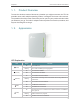
Chapter 1 Get to Know About Your Router 1. 1. Product Overview 1. 2. Appearance To meet the wireless needs of almost any situation you might encounter, the TP-Link portable router, with multiple operating modes, is designed for home and travel use. The portable size of the router means that you can put it in your pocket and take it with you wherever you go. The built-in adapter makes it perfect for travelers, students, and anyone else living life on the go.
Chapter 1 Get to Know About Your Router Port and Button Description Item Mode Switch WAN/LAN Power 3G/4G USB WPS Description This button is used to switch the operation mode of the router. This port functions as the WAN port in Router mode and as the LAN port in Hotspot, Access Point, Range Extender and Client mode. The port is used to connect the power adapter. This port is used to plug a 3G/4G modem or a USB disk into. To establish WPS connection, press this button.
Chapter 2 Connect the Hardware This chapter contains the following sections: • Position Your Router • Connect Your Router
Connect the Hardware Chapter 2 2. 1. Position Your Router • The Product should not be located where it will be exposed to moisture or excessive heat. • Place the router in a location where it can be connected to the various devices as well as to a power source. • Make sure the cables and power cord are safely placed out of the way so they do not create a tripping hazard. • The router can be placed on a shelf or desktop.
Connect the Hardware Chapter 2 1. Switch the operation mode to AP/Rng Ext/Client and connect the hardware according to Step A to D. 2. Connect your device to the router wirelessly. The Wi-Fi network name and password are on the router’s label. Note: If the hotel’s internet has an authentication process, you will need to authenticate it on EACH device. Internet Wired Router A 2. 2. 3. B C D Range Extender Mode Repeat signal from an existing wireless network.
Connect the Hardware Chapter 2 Internet A B Host AP OR Smart TV 2. 2. 5. OR Desktop Other Device Hotspot Router Mode In Hotspot Router mode, the router enables multiple users to share internet connection from WISP. 1. Switch the operation mode to Share Hotspot and plug the router into an electrical outlet within the range of the public hotspot. 2. Connect your device to the router wirelessly or via an Ethernet cable. The Wi-Fi network name and password are on the router’s label.
Chapter 3 Set Up Internet Connection Via Quick Setup Wizard This chapter introduces how to connect your router to the internet via the web-based Quick Setup Wizard.
Chapter 3 3. 1. Set Up Internet Connection Via Quick Setup Wizard Log Into the Router With a Web-based utility, it is easy to configure and manage the rouer. The Web-based utility can be used on any Windows, Macintosh or UNIX OS with a Web browser, such as Microsoft Internet Explorer, Mozilla Firefox or Apple Safari. Follow the steps below to log into your router. 1. Set up the TCP/IP Protocol in Obtain an IP address automatically mode on your computer. 2. Visit http://tplinkwifi.
Chapter 3 Set Up Internet Connection Via Quick Setup Wizard Note: • If you use DSL line and you are only provided an account name and a password by your ISP, choose PPPoE. • If you use cable TV or fiber cable, choose Dynamic IP. • If you are provided more information such as IP address, Subnet Mask and Default Gateway, choose Static IP. • Contact your ISP if you are not sure about the WAN connection information. You can also select AutoDetect to let the router detect your connection type automatically.
Chapter 3 Set Up Internet Connection Via Quick Setup Wizard 4. Click Finish to complete the configuration. Now your computers and Wi-Fi devices can connect to the Internet! 3. 2. 2. Access Point Mode 1. Either customize your Wireless Network Name and Wireless Password or keep the default ones, and then click Next. 2. Select the LAN IP type of the router or leave the default setting Smart IP for most cases, and then click Next.
Chapter 3 Set Up Internet Connection Via Quick Setup Wizard 3. Click Reboot to complete the configuration. 3. 2. 3. Range Extender Mode 1. Click Survey to find your host network and click Connect. Enter the host network’s password in the Wireless Password field, and then click Next. 2. Select the LAN IP type of the router or leave the default setting Smart IP for most cases, and then click Next.
Chapter 3 Set Up Internet Connection Via Quick Setup Wizard 3. Click Reboot to complete the configuration. 4. Relocate the router about halfway between your host AP and the Wi-Fi dead zone. The extended network shares the same network name and password as your host network. 3. 2. 4. Client Mode 1. Click Survey to find your host network and click Connect. Enter the host network’s password in the Wireless Password field, and then click Next.
Chapter 3 Set Up Internet Connection Via Quick Setup Wizard 2. Select the LAN IP type of the router or leave the default setting Smart IP for most cases, and then click Next. 3. Click Reboot to complete the configuration. Now you can connect your wired-only device to the router’s LAN or LAN/WAN port using an Ethernet cable. 3. 2. 5. Hotspot Router Mode 1. Select the WAN Connection Type. When using the router in a hotel room or a small office, select Dynamic IP.
Chapter 3 Set Up Internet Connection Via Quick Setup Wizard 2. In this case, we take dynamic IP that requires no more parameters for instance. For other connection types, please enter the parameters provided by your ISP. 3. Click Survey to find the public Wi-Fi network and click Connect. Enter the public Wi-Fi password in the Password field. In the AP Setting section, either customize your Local SSID and Wireless Password or keep the default ones, and then click Next. 4.
Chapter 4 Configure the Router in Standard Wireless Router This chapter presents how to configure the various features of the router working as a standard wireless router.
Chapter 4 4. 1. Status 1. Visit http://tplinkwifi.net, and log in with the username and password you set for the router. 2. Go to Status. You can view the current status information of the router. • Firmware Version - The version information of the router’s firmware. • Hardware Version - The version information of the router’s hardware. • LAN - This field displays the current settings of the LAN, and you can configure them on the Network > LAN page.
Chapter 4 • Name (SSID) - The SSID of the router. • Channel Width - The current wireless channel width in use. • • • • Mode - The current wireless working mode in use. Channel - The current wireless channel in use. MAC Address - The physical address of the router. WDS Status - The status of WDS connection. • WAN - This field displays the current settings of the WAN, and you can configure them on the Network > WAN page. • MAC Address - The physical address of the WAN port.
Chapter 4 Method ONE: Press the WPS Button on Your Client Device 1. Keep the WPS Status as Enabled and click Add Device. 2. Select Press the button of the new device in two minutes and click Connect. 3. Within two minutes, press the WPS button on your client device. 4. A success message will appear on the WPS page if the client device has been successfully added to the router’s network. Method TWO: Enter the Client’s PIN 1. Keep the WPS Status as Enabled and click Add Device. 2.
Chapter 4 3. A success message will appear on the WPS page if the client device has been successfully added to the router’s network. Method Three: Enter the Router’s PIN 1. Keep the WPS Status as Enabled and get the Current PIN of the router. 2. Enter the router’s current PIN on your client device to join the router’s Wi-Fi network. 4. 3. Working Mode 1. Visit http://tplinkwifi.net, and log in with the username and password you set for the router. 2. Go to Working Mode. 3.
Chapter 4 Click Release to release the IP parameters. • MTU Size - The normal MTU (Maximum Transmission Unit) value for most Ethernet networks is 1500 Bytes. It is not recommended that you change the default MTU size unless required by your ISP. • Use These DNS Servers - If your ISP providess you one or two DNS addresses, select Use These DNS Servers and enter the primary and secondary addresses. Otherwise, the DNS servers will be assigned dynamically from your ISP.
Chapter 4 • Subnet Mask - Enter the subnet mask in dotted-decimal notation provided by your ISP. Normally 255.255.255.0 is used as the subnet mask. • Default Gateway - Enter the gateway IP address in dotted-decimal notation provided by your ISP. • MTU Size - The normal MTU (Maximum Transmission Unit) value for most Ethernet networks is 1500 Bytes. It is not recommended that you change the default MTU size unless required by your ISP.
Chapter 4 • • • Note: field. Otherwise, enter the number of minutes you want to have elapsed before your Internet access disconnects. Connect Automatically - The connection can be re-established automatically when it is down. Time-based Connecting - The connection will only be established in the period from the start time to the end time (both are in HH:MM format). Connect Manually - You can click Connect/Disconnect to connect/disconnect immediately.
Chapter 4 • Detect Online Interval - The router will detect Access Concentrator online at every interval. The default value is 0. You can input the value between 0 and 120. The value 0 means no detect. • Primary DNS/Secondary DNS - If your ISP does not automatically assign DNS addresses to the router, please select Use the following DNS servers and enter the IP address in dotted-decimal notation of your ISP’s primary DNS server. If a secondary DNS server address is available, enter it as well.
Chapter 4 • • Connect Automatically - The connection can be re-established automatically when it is down. Connect Manually - You can click Connect/Disconnect to connect/disconnect immediately. This mode also supports the Max Idle Time function as Connect on Demand mode. The Internet connection can be disconnected automatically after a specified inactivity period (Max Idle Time) and not be able to re-establish when you attempt to access the Internet again.
Chapter 4 • Dynamic IP/ Static IP - Select either as required by your ISP. If Static IP is selected, please enter the IP address, subnet marsk, gateway and DNS also provided by your ISP. • Internet IP Address/ Internet DNS - The Internet IP address and DNS server address assigned by L2TP server.
Chapter 4 • User Name/Password - Enter the user name and password provided by your ISP. These fields are case-sensitive. • Confirm Password - Enter the Password provided by your ISP again to ensure the password you entered is correct. • Connect/Disconnect - Click this button to connect or disconnect immediately. • Dynamic IP/ Static IP - Select either as required by your ISP. If Static IP is selected, please enter the IP address, subnet marsk, gateway and DNS also provided by your ISP.
Chapter 4 • • Connect Automatically - The connection can be re-established automatically when it is down. Connect Manually - You can click Connect/Disconnect to connect/disconnect immediately. This mode also supports the Max Idle Time function as Connect on Demand mode. The Internet connection can be disconnected automatically after a specified inactivity period (Max Idle Time) and not be able to re-establish when you attempt to access the Internet again.
Chapter 4 • MAC Address - The physical address of the LAN ports. The value can not be changed. • IP Address - Enter the IP address in dotted-decimal notation of your router (factory default - 192.168.0.254). • Subnet Mask - An address code that determines the size of the network. Normally 255.255.255.0 is used as the subnet mask. • IGMP Proxy - The Internet Group Management Protocol (IGMP) feature allow you to watch TV on IPTV-supported devices on the LAN .
Chapter 4 address). It is strongly recommended that you change your network name (SSID). This value is case-sensitive. For example, TEST is NOT the same as test. • Mode - Select the desired mode. It is strongly recommended that you keep the default setting 11bgn mixed, so that all 802.11b/g/n wireless devices can connect to the router. Note: If 11bg mixed mode is selected, the Channel Width field will turn grey and the value will become 20M, and cannot be changed.
Chapter 4 • WEP Index - This option should be chosen if the key type is WEP (ASCII) or WEP (HEX). It indicates the index of the WEP key. • Auth Type - This option should be chosen if the key type is WEP (ASCII) or WEP (HEX). It indicates the authorization type of the Root AP. • Password - If the AP your router is going to connect needs password, you need to fill the password in this blank. 4. 5. 2. Wireless Security 1. Visit http://tplinkwifi.
Chapter 4 • • Wireless Password - Enter ASCII or Hexadecimal characters. For Hexadecimal, the length should be between 8 and 64 characters; for ASCII, the length should be between 8 and 63 characters. Group Key Update Period - Specify the group key update interval in seconds. The value can be 0 or at least 30. Enter 0 to disable the update. • WPA /WPA2-Enterprise - It’s based on Radius Server. • Version - Select Automatic, WPA or WPA2.
Chapter 4 network by their MAC addresses. For example, you want the wireless client A with the MAC address 00-0A-EB-B0-00-0B and the wireless client B with the MAC address 00-0A-EB-00-07-5F to access the router, but other wireless clients cannot access the router. How can I do that? 1. Visit http://tplinkwifi.net, and log in with the username and password you set for the router. 2. Go to Wireless > Wireless MAC Filtering. 3. Click Enable to enable the Wireless MAC Filtering function. 4.
Chapter 4 2. Go to Wireless > Wireless Advanced. 3. Configure the advanced settings of your wireless network and click Save. Note: If you are not familiar with the setting items on this page, it’s strongly recommended to keep the provided default values; otherwise it may result in lower wireless network performance. • Transmit Power - Select High, Middle or Low which you would like to specify for the router. High is the default setting and recommended.
Chapter 4 • Enable AP Isolation - This function isolates all connected wireless stations so that wireless stations cannot access each other through WLAN. This function will be disabled if WDS / Bridge is enabled. 4. 5. 5. Wireless Statistics 1. Visit http://tplinkwifi.net, and log in with the username and password you set for the router. 2. Go to Wireless > Wireless Statistics to check the data packets sent and received by each client device connected to the router.
Chapter 4 • DHCP Server - Enable or disable the DHCP server. If disabled, you must have another DHCP server within your network or else you must configure the computer manually. • Start IP Address - Specify an IP address for the DHCP Server to start with when assigning IP addresses. 192.168.0.100 is the default start address. • End IP Address - Specify an IP address for the DHCP Server to end with when assigning IP addresses. 192.168.0.199 is the default end address.
Chapter 4 • Client Name - The name of the DHCP client. • MAC Address - The MAC address of the DHCP client. • Assigned IP - The IP address that the router has allocated to the DHCP client. • Lease Time - The time of the DHCP client leased. After the dynamic IP address has expired, a new dynamic IP address will be automatically assigned to the user. You cannot change any of the values on this page. To update this page and show the current connected devices, click Refresh. 4. 6. 3.
Chapter 4 problem that external hosts cannot initiatively communicate with the specified devices in the local network. With the forwarding feature, the router can traverse the isolation of NAT so that clients on the Internet can reach devices on the LAN and realize some specific functions. The TP-Link router includes four forwarding rules. If two or more rules are set, the priority of implementation from high to low is Virtual Servers, Port Triggering, UPNP and DMZ. 4. 7. 1.
Chapter 4 5. Leave the status as Enabled and click Save. Done! Note: • It is recommended to keep the default settings of Internal Port and Protocol if you are not clear about which port and protocol to use. • If the service you want to use is not in the Common Service Port list, you can enter the corresponding parameters manually. You should verify the port number that the service needs. • You can add multiple virtual server rules if you want to provide several services in a router.
Chapter 4 4. Leave the status as Enabled and click Save. Note: • You can add multiple port triggering rules as needed. • The triggering ports can not be overlapped. • If the application you need is not listed in the Common Applications list, please enter the parameters manually. You should verify the incoming ports the application uses first and enter them in Incoming Ports field. You can input at most 5 groups of ports (or port sections). Every group of ports must be set apart with “,”.
Chapter 4 4. Select Enable and enter the IP address 192.168.0.100 in the DMZ Host IP Address filed. 5. Click Save. Done! 4. 7. 4. You’ve set your PC to a DMZ host and now you can make a team to game with other players. UPnP The UPnP (Universal Plug and Play) protocol allows the applications or host devices to automatically find the front-end NAT device and send request to it to open the corresponding ports.
Chapter 4 4. 8. Security 4. 8. 1. Basic Security This function allows you to protect your home network from cyber attacks and unauthorized users by implementing these network security functions. 1. Visit http://tplinkwifi.net, and log in with the username and password you set for the router. 2. Go to Security > Basic Security, and you can enable or disable the security functions. • Firewall - A firewall protects your network from Internet attacks.
Chapter 4 • VPN - VPN Passthrough must be enabled if you want to allow VPN tunnels using IPSec, PPTP or L2TP protocols to pass through the router’s firewall. • • • PPTP Passthrough - Point-to-Point Tunneling Protocol (PPTP) allows the Pointto-Point Protocol (PPP) to be tunneled through an IP network. If you want to allow PPTP tunnels to pass through the router, you can keep the default (Enabled).
Chapter 4 • Packets Statistics Interval (5~60) - The default value is 10. Select a value between 5 and 60 seconds from the drop-down list. The Packets Statistics Interval value indicates the time section of the packets statistics. The result of the statistics is used for analysis by SYN Flood, UDP Flood and ICMP-Flood. • DoS Protection - Denial of Service protection. Select Enable or Disable to enable or disable the DoS protection function. Only when it is enabled, will the flood filters be enabled.
Chapter 4 • Ignore Ping Packet From WAN Port - The default setting is disabled. If enabled, the ping packet from the Internet cannot access the router. • Forbid Ping Packet From LAN Port - The default setting is disabled. If enabled, the ping packet from LAN cannot access the router. This function can be used to defend against some viruses. 3. Click Save. 4. Click Blocked DoS Host List to display the DoS host table by blocking. 4. 8. 3. Local Management 1. Visit http://tplinkwifi.
Chapter 4 4. 8. 4. Remote Management 1. Visit http://tplinkwifi.net, and log in with the username and password you set for the router. 2. Go to Security > Remote Management, and you can manage your router from a remote device via the Internet. • Web Management Port - Web browser access normally uses the standard HTTP service port 80. This router’s default remote management web port number is 80.
Chapter 4 4. Go to Parental Control. 5. Select Enable and enter the MAC address 00-11-22-33-44-BB in the MAC Address of Parental PC field. 6. Click Add New. 7. Enter appropriate parameters in corresponding fields. • Enter 00-11-22-33-44-AA in the MAC Address of Children’s PC field. • • • Enter www.tp-link.com in the Allowed Website Name field. Select Schedule_1 you created from the Effective Time drop-down list. In the Status field, select Enable.
Chapter 4 4. 10. Access Control Access Control is used to deny or allow specific client devices to access your network with access time and content restrictions. I want to: How can I do that? Deny or allow specific client devices to access my network with access tiem and content restrictions. For example, If you want to restrict the Internet activities of host with MAC address 00-11-22-33-44-AA on the LAN to access www.tp-link.com only, please follow the steps below: 1. Visit http://tplinkwifi.
Chapter 4 3 ) Click Save. 4. Go to Access Control > Schedule and configure the schedule settings: 1 ) Click Add New. 2 ) Create a unique description (e.g. schedule_1) for the schedule in the Schedule Description field and set the day(s) and time period. 3 ) Click Save. 5. Go to Access Control > Rule and add a new access control rule. 1 ) Click Add New. 2 ) Give a name for the rule in the Rule Name field.
Chapter 4 3 ) Leave the status as Enabled as click Save. 6. Select Enable Internet Access Control to enable Access Control function. 7. Select Allow the packets specified by any enabled access control policy to pass through the Router as the default filter policy and click Save. Done! Now only the specific host(s) can visit the target(s) within the scheduled time period. 4. 11.
Chapter 4 2. Enter the following information. • • • Destination Network - The Destination Network is the address of the network or host that you want to assign to a static route. Subnet Mask - The Subnet Mask determines which portion of an IP address is the network portion, and which portion is the host portion. Default Gateway - This is the IP address of the default gateway device that allows the contact between the router and the network or host. 3.
Chapter 4 • Destination Network - The Destination Network is the address of the network or host to which the static route is assigned. • Subnet Mask - The Subnet Mask determines which portion of an IP address is the network portion, and which portion is the host portion. • Gateway - This is the IP address of the gateway device that allows for contact between the Router and the network or host.
Chapter 4 • Description - This is the information about the rules such as address range. • Egress Bandwidth - This field displays the max and min upload bandwidth through the WAN port. The default is 0. • Ingress Bandwidth - This field displays the max and min download bandwidth through the WAN port. The default is 0. • Enable - This field displays the status of the rule. • Modify - Click Modify/Delete to edit/delete the rule. ¾¾ To add a Bandwidth control rule: 1. Click Add New. 2.
Chapter 4 4. Click Save. ¾¾ To add IP & MAC Binding entries: 1. Click Add New. 2. Select the Bind checkbox. 3. Enter the MAC address and IP address. 4. Click Save. ¾¾ To modify or delete an existing entry: 1. Find the desired entry in the table. 2. Click Modify or Delete in the Modify column. ¾¾ To find an existing entry: 1. Click Find. 2. Enter the MAC address or IP address in the corresponding field. 3. Click Find on this page as shown below. 4. 13. 2.
Chapter 4 • MAC Address - The MAC address of the listed computer on the LAN. • IP Address - The assigned IP address of the listed computer on the LAN. • Status - Indicates whether or not the MAC and IP addresses are bound. • Configure - Load or delete an item. • • Load - Load the item to the IP & MAC Binding list. Delete - Delete the item. • Click Bind All to bind all the current items. • Click Load All to load all items to the IP & MAC Binding list. • Click Refresh to refresh all items.
Chapter 4 To set up for DDNS, follow these instructions: 1. Enter the Domain Name received from your dynamic DNS service provider. 2. Enter the User Name for your DDNS account. 3. Enter the Password for your DDNS account. 4. Click Login. 5. Click Save. • Connection Status - The status of the DDNS service connection is displayed here. • Logout - Click Logout to log out of the DDNS service. Dyndns DDNS If the dynamic DNS Service Provider you select is www.dyn.com, the following page will appear.
Chapter 4 2. Enter the Password for your DDNS account. 3. Enter the Domain Name you received from dynamic DNS service provider here. 4. Click Login. 5. Click Save. • Connection Status - The status of the DDNS service connection is displayed here. • Logout - Click Logout to log out of the DDNS service. No-ip DDNS If the dynamic DNS Service Provider you select is www.noip.com, the following page will appear. To set up for DDNS, follow these instructions: 1. Enter the User Name for your DDNS account.
Chapter 4 ¾¾ To set time manually: 3. Select your local time zone. 4. Enter the Date in Month/Day/Year format. 5. Enter the Time in Hour/Minute/Second format. 6. Click Save. ¾¾ To set time automatically: 7. Select your local time zone. 8. Enter the address or domain of the NTP Server I or NTP Server II. 9. Click Get GMT to get time from the Internet if you have connected to the Internet. ¾¾ To set Daylight Saving Time: 1. Select Enable DaylightSaving. 2.
Chapter 4 • Diagnostic Tool - Select one diagnostic tool. • • Ping - This diagnostic tool troubleshoots connectivity, reachability, and name resolution to a given host or gateway. Tracerouter - This diagnostic tool tests the performance of a connection. Note: You can use ping/traceroute to test both numeric IP address or domain name. If pinging/tracerouting the IP address is successful, but pinging/tracerouting the domain name is not, you might have a name resolution problem.
Chapter 4 Note: Only one user can use this tool at one time. Options “Number of Pings”, “Ping Size” and “Ping Timeout” are used for the Ping function. Option “Tracert Hops” is used for the Tracert function. 4. 15. 3. Firmware Upgrade TP-Link is dedicated to improving and richening the product features, giving users a better network experience. We will release the latest firmware at TP-Link official website. You can download the latest firmware file from the Support page of our website www.tp-link.
Chapter 4 • • The default IP Address: 192.168.0.1 The default Subnet Mask: 255.255.255.0 4. 15. 5. Backup & Restore The configuration settings are stored as a configuration file in the router. You can backup the configuration file in your computer for future use and restore the router to the previous settings from the backup file when needed. 1. Visit http://tplinkwifi.net, and log in with the username and password you set for the router. 2. Go to System Tools > Backup & Restore.
Chapter 4 4. 15. 7. Password 1. Visit http://tplinkwifi.net, and log in with the username and password you set for the router. 2. Go to System Tools > Password, and you can change the factory default username and password of the router. It is strongly recommended that you change the default username and password of the router, for all users that try to access the router’s web-based utility or Quick Setup will be prompted for the router’s username and password.
Chapter 4 • From - Your mail box address. The router will connect it to send logs. • SMTP Server - Your smtp server. It corresponds with the mailbox filled in the From field. You can log on the relevant website for help if you are not clear with the address. • • To - Recipient’s mail address. The destination mailbox which will receive logs Authentication - Most SMTP Server requires Authentication. It is required by most mailboxes that need user name and password to log in.
Chapter 4 • Mail Log - Click to send an email of current logs manually according to the address and validation information set in Mail Settings. • Clear Log - All the logs will be deleted from the router permanently, not just from the page. Click Next to go to the next page, or click Previous to return to the previous page. 4. 15. 9. Statistics 1. Visit http://tplinkwifi.net, and log in with the username and password you set for the router. 2.
Chapter 4 Packets The total number of packets received and transmitted in the last Packets Statistic interval seconds. Bytes Current ICMP Tx UDP Tx TCP SYN Tx Modify Reset Delete The total number of bytes received and transmitted in the last Packets Statistic interval seconds. The number of the ICMP packets transmitted to WAN per second at the specified Packets Statistics interval. It is shown like “current transmitting rate / Max transmitting rate”.
Chapter 5 Configure the Router in Access Point Mode This chapter presents how to configure the various features of the router working as an Access Point.
Chapter 5 5. 1. Status 1. Visit http://tplinkwifi.net, and log in with the username and password you set for the router. 2. Go to Status. You can view the current status information of the router in Access Point Mode. • Firmware Version - The version information of the router’s firmware. • Hardware Version - The version information of the router’s hardware. • Wired - This field displays the current settings of the LAN, and you can configure them on the Network > LAN page.
Chapter 5 • Channel - The current wireless channel in use. • Channel Width - The current wireless channel width in use. • • Mode - The current wireless mode which the router works on. MAC Address - The physical address of the router. • Traffic Statistics - The router’s traffic statistics. • Received (Bytes) - Traffic in bytes received from the WAN port. • Sent (Bytes) - Traffic in bytes sent out from the WAN port. • • Received (Packets) - Traffic in packets received from the WAN port.
Chapter 5 3. Within two minutes, press the WPS button on your client device. 4. A success message will appear on the WPS page if the client device has been successfully added to the router’s network. Method TWO: Enter the Client’s PIN 1. Keep the WPS Status as Enabled and click Add Device. 2. Select Enter the new device’s PIN, enter your client device’s current PIN in the PIN filed and click Connect. 3.
Chapter 5 2. Enter the router’s current PIN on your client device to join the router’s Wi-Fi network. 5. 3. Working Mode 1. Visit http://tplinkwifi.net, and log in with the username and password you set for the router. 2. Go to Working Mode. 3. Select the working mode as needed and click Save. 5. 4. Network 5. 4. 1. LAN 1. Visit http://tplinkwifi.net, and log in with the username and password you set for the router. 2. Go to Network > LAN. 3.