User Guide 450Mbps Wireless N Router TL-WR940N REV6.0.
Contents About This Guide .........................................................................................................1 Chapter 1. Get to Know About Your Router . . . . . . . . . . . . . . . . . . . . . . . . . . .2 1. 1. 1. 2. Product Overview. . . . . . . . . . . . . . . . . . . . . . . . . . . . . . . . . . . . . . . . . . . . . . . . . . . . . . . . . . . . 3 Panel Layout. . . . . . . . . . . . . . . . . . . . . . . . . . . . . . . . . . . . . . . . . . . . . . . . . . . . . . . . . . . .
4. 8. 4. 7. 3.Address Reservation . . . . . . . . . . . . . . . . . . . . . . . . . . . . . . . . . . . . . . . . . . . . . . . . . 37 Forwarding . . . . . . . . . . . . . . . . . . . . . . . . . . . . . . . . . . . . . . . . . . . . . . . . . . . . . . . . . . . . . . . . . 37 4. 8. 1.Virtual Servers . . . . . . . . . . . . . . . . . . . . . . . . . . . . . . . . . . . . . . . . . . . . . . . . . . . . . . . 37 4. 8. 2.Port Triggering . . . . . . . . . . . . . . . . . . . . . . . . . . . . . . . . . . . .
5. 1. 5. 2. 5. 3. 5. 4. Status . . . . . . . . . . . . . . . . . . . . . . . . . . . . . . . . . . . . . . . . . . . . . . . . . . . . . . . . . . . . . . . . . . . . . . 73 WPS . . . . . . . . . . . . . . . . . . . . . . . . . . . . . . . . . . . . . . . . . . . . . . . . . . . . . . . . . . . . . . . . . . . . . . . . 74 Working Mode . . . . . . . . . . . . . . . . . . . . . . . . . . . . . . . . . . . . . . . . . . . . . . . . . . . . . . . . . . . . . . 76 Network . . . . . . . . . . . . . . . . . . .
6. 5. DHCP. . . . . . . . . . . . . . . . . . . . . . . . . . . . . . . . . . . . . . . . . . . . . . . . . . . . . . . . . . . . . . . . . . . . . .104 6. 5. 1.DHCP Settings . . . . . . . . . . . . . . . . . . . . . . . . . . . . . . . . . . . . . . . . . . . . . . . . . . . . . .104 6. 5. 2.DHCP Client List . . . . . . . . . . . . . . . . . . . . . . . . . . . . . . . . . . . . . . . . . . . . . . . . . . . .105 6. 6. 6. 5. 3.Address Reservation . . . . . . . . . . . . . . . . . . . . . . . . . . . . .
About This Guide This guide is a complement to Quick Installation Guide. The Quick Installation Guide provides instructions for quick internet setup, while this guide contains details of each function and demonstrates how to configure them. When using this guide, please notice that features of the router may vary slightly depending on the model and software version you have, and on your location, language, and Internet service provider.
Chapter 1 Get to Know About Your Router Chapter 1 Get to Know About Your Router This chapter introduces what the router can do and shows its appearance.
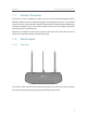
Chapter 1 1. 1. Get to Know About Your Router Product Overview The TP-Link router is designed to fully meet the need of Small Office/Home Office (SOHO) networks and users demanding higher networking performance. The powerful antennas ensure continuous Wi-Fi signal to all your devices while boosting widespread coverage throughout your home, and the built-in Ethernet ports supply high-speed connection to your wired devices.
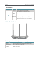
Chapter 1 Get to Know About Your Router LED Explanation LED Status Orange On Indication Power is on, but there is no internent connection. Router mode: The router is connected to the internet. Blue On Range Extender mode: The router is connected to the host network. Access Point mode: At least one of the router’s WAN/LAN ports is connected. Blinking Slowly Blinking Quickly 1. 2. 2. The system is starting up or firmware is being upgraded. Do not disconnect or power off your router.
Chapter 1 Get to Know About Your Router Item Description Press this button, and immediately press the WPS button on your device. The WPS LED of the router should change from flashing to solid on, indicating successful WPS Wi-Fi/WPS Button connection. Press and hold this button for more than 5 seconds to turn on or off the wireless function of your router. Internet Port For connecting to a DSL/Cable modem, or an Ethernet port.
Chapter 2 Connect to the Internet This chapter contains the following sections: • Position Your Router • Connect to the Internet
Chapter 2 2. 1. Connect to the Internet Position Your Router • The product should not be located in a place where it will be exposed to moisture or excessive heat. • Place the router in a location where it can be connected to multiple devices as well as to a power source. • Make sure the cables and power cord are safely placed out of the way so they do not create a tripping hazard. • The router can be placed on a shelf or desktop.
Chapter 2 Connect to the Internet 5 ) Verify that the hardware connection is correct by checking these LEDs. Power On Wi-Fi On Internet On Tips: If the Wi-Fi LED is off, press and hold the WPS/Wi-Fi button until it is on. 2. Connect your computer to the router. • Method 1: Wired Turn off the Wi-Fi on your computer and connect the devices as shown below. Ethernet cable • Method 2: Wirelessly 1 ) Find the SSID (Network Name) and Wireless Password printed on the label at the bottom of the router.
Chapter 2 Connect to the Internet 2 ) Immediately press the WPS button on your router. Close to 3. Enter http://tplinkwifi.net or 192.168.0.1 in the address bar of a web browser. Use admin for both username and password, and then click Login. Note: If the above screen does not appear, please refer to FAQ > Q3. 4. After successful login, select Standard Wireless Router mode and follow Quick Setup to complete the configuration. 5.
Chapter 2 Connect to the Internet Note: If the above screen does not appear, please refer to FAQ > Q3. 4. After successful login, select Repeater mode and follow Quick Setup to complete the configuration. Tips: Click Survey to choose your host network and fill in its wireless password. 5. Relocate: Place the router between your host router and the Wi-Fi dead zone. The location you choose must be within the range of your existing host network.
Chapter 2 Connect to the Internet 4. Enter http://tplinkwifi.net in the address bar of a web browser. Use admin for both usernane and password, and then click Login. Note: If the above screen does not appear, please refer to FAQ > Q3. 5. After successful login, select Access Point mode and follow the Quick Setup to complete the configuration. Note: If you want to change the default SSID (Network Name) and the password, please modify them on the Wireless page of Quick Setup. 6.
Chapter 3 Log In This chapter introduces how to log in to the web management page of the router.
Chapter 3 Log In With the web management page, it is easy to configure and manage the router. The webbased utility can be used on any Windows, Macintosh or UNIX OS with a web browser, such as Microsoft Internet Explorer, Mozilla Firefox or Apple Safari. Follow the steps below to log in to your router. 1. Set up the TCP/IP Protocol in Obtain an IP address automatically mode on your computer. 2. Visit http://tplinkwifi.net, and log in with the username and password you set for the router.
Chapter 4 Configure the Router in Standard Wireless Router This chapter presents how to configure the various features of the router working as a standard wireless router.
&RQƮJXUH WKH 5RXWHU LQ 6WDQGDUG :LUHOHVV 5RXWHU Chapter 4 4. 1. Status 1. Visit http://tplinkwifi.net, and log in with the username and password you set for the router. 2. Go to Status. You can view the current status information of the router. • Firmware Version - The version information of the router’s firmware. • Hardware Version - The version information of the router’s hardware. • LAN - This field displays the current settings of the LAN, and you can configure them on the Network > LAN page.
&RQƮJXUH WKH 5RXWHU LQ 6WDQGDUG :LUHOHVV 5RXWHU Chapter 4 • Name (SSID) - The SSID of the router. • Mode - The current wireless working mode. • Channel Width - The current wireless channel width. • Channel - The current wireless channel. • MAC Address - The physical address of the router. • WDS Status - The status of WDS connection. • WAN - This field displays the current settings of the WAN, and you can configure them on the Network > WAN page.
Chapter 4 &RQƮJXUH WKH 5RXWHU LQ 6WDQGDUG :LUHOHVV 5RXWHU Method ONE: Press the WPS Button on Your Client Device 1. Keep the WPS Status as Enabled and click Add Device. 2. Select Press the button of the new device in two minutes and click Connect. 3. Within two minutes, press the WPS button on your client device. 4. A success message will appear on the WPS page if the client device has been successfully added to the router’s network. Method TWO: Enter the Client’s PIN 1.
&RQƮJXUH WKH 5RXWHU LQ 6WDQGDUG :LUHOHVV 5RXWHU Chapter 4 3. A success message will appear on the WPS page if the client device has been successfully added to the router’s network. Method Three: Enter the Router’s PIN 1. Keep the WPS Status as Enabled and get the Current PIN of the router. 2. Enter the router’s current PIN on your client device to join the router’s Wi-Fi network. 4. 3. Working Mode 1. Visit http://tplinkwifi.net, and log in with the username and password you set for the router. 2.
Chapter 4 &RQƮJXUH WKH 5RXWHU LQ 6WDQGDUG :LUHOHVV 5RXWHU Click Release to release the IP parameters. • MTU Size - The normal MTU (Maximum Transmission Unit) value for most Ethernet networks is 1500 Bytes. It is not recommended that you change the default MTU size unless required by your ISP. • Use These DNS Servers - If your ISP providess you one or two DNS addresses, select Use These DNS Servers and enter the primary and secondary addresses.
Chapter 4 &RQƮJXUH WKH 5RXWHU LQ 6WDQGDUG :LUHOHVV 5RXWHU • Subnet Mask - Enter the subnet mask in dotted-decimal notation provided by your ISP. Normally 255.255.255.0 is used as the subnet mask. • Default Gateway - Enter the gateway IP address in dotted-decimal notation provided by your ISP. • MTU Size - The normal MTU (Maximum Transmission Unit) value for most Ethernet networks is 1500 Bytes. It is not recommended that you change the default MTU size unless required by your ISP.
Chapter 4 &RQƮJXUH WKH 5RXWHU LQ 6WDQGDUG :LUHOHVV 5RXWHU field. Otherwise, enter the number of minutes you want to have elapsed before your internet access disconnects. • Connect Automatically - The connection can be re-established automatically when it is down. • Time-based Connecting - The connection will only be established in the period from the start time to the end time (both are in HH:MM format). • Connect Manually - You can click Connect/Disconnect to connect/disconnect immediately.
Chapter 4 &RQƮJXUH WKH 5RXWHU LQ 6WDQGDUG :LUHOHVV 5RXWHU • Primary DNS/Secondary DNS - If your ISP does not automatically assign DNS addresses to the router, please select Use the following DNS servers and enter the IP address in dotted-decimal notation of your ISP’s primary DNS server. If a secondary DNS server address is available, enter it as well. BigPond Cable If your ISP provides BigPond cable connection, please select BigPond Cable.
Chapter 4 • &RQƮJXUH WKH 5RXWHU LQ 6WDQGDUG :LUHOHVV 5RXWHU Connect Manually - You can click Connect/Disconnect to connect/disconnect immediately. This mode also supports the Max Idle Time function as Connect on Demand mode. The internet connection can be disconnected automatically after a specified inactivity period (Max Idle Time) and not be able to re-establish when you attempt to access the internet again.
Chapter 4 &RQƮJXUH WKH 5RXWHU LQ 6WDQGDUG :LUHOHVV 5RXWHU • User Name/Password - Enter the user name and password provided by your ISP. These fields are case-sensitive. • Confirm Password - Enter the Password provided by your ISP again to ensure the password you entered is correct. • Connect/Disconnect - Click this button to connect or disconnect immediately. • Dynamic IP/ Static IP - Select either as required by your ISP.
Chapter 4 &RQƮJXUH WKH 5RXWHU LQ 6WDQGDUG :LUHOHVV 5RXWHU PPTP/Russia PPTP If your ISP provides PPTP connection, please select PPTP/Russia PPTP. • User Name/Password - Enter the user name and password provided by your ISP. These fields are case-sensitive. • Confirm Password - Enter the Password provided by your ISP again to ensure the password you entered is correct. • Connect/Disconnect - Click this button to connect or disconnect immediately.
&RQƮJXUH WKH 5RXWHU LQ 6WDQGDUG :LUHOHVV 5RXWHU Chapter 4 field. Otherwise, enter the number of minutes you want to have elapsed before your internet access disconnects. • Connect Automatically - The connection can be re-established automatically when it is down. • Connect Manually - You can click Connect/Disconnect to connect/disconnect immediately. This mode also supports the Max Idle Time function as Connect on Demand mode.
&RQƮJXUH WKH 5RXWHU LQ 6WDQGDUG :LUHOHVV 5RXWHU Chapter 4 • MAC Address - The physical address of the LAN ports. The value can not be changed. • IP Address - Enter the IP address in dotted-decimal notation of your router (factory default - 192.168.0.254). • Subnet Mask - An address code that determines the size of the network. Normally 255.255.255.0 is used as the subnet mask. • IGMP Proxy - The internet Group Management Protocol (IGMP) feature allow you to watch TV on IPTV-supported devices on the LAN .
Chapter 4 &RQƮJXUH WKH 5RXWHU LQ 6WDQGDUG :LUHOHVV 5RXWHU • Wireless Network Name - Enter a string of up to 32 characters. The default SSID is TP-Link_XXXX (XXXX indicates the last unique four numbers of each router’s MAC address). It is strongly recommended that you change your network name (SSID). This value is case-sensitive. For example, TEST is NOT the same as test. • Mode - Select the desired mode. It is strongly recommended that you keep the default setting 11bgn mixed, so that all 802.
&RQƮJXUH WKH 5RXWHU LQ 6WDQGDUG :LUHOHVV 5RXWHU Chapter 4 • WDS Mode - This field determines which WDS Mode will be used. It is not necessary to change the WDS mode unless you notice network communication problems with root AP. If you select Auto, then the router will choose the appropriate WDS mode automatically. • Key type - This option should be chosen according to the AP’s security configuration. It is recommended that the security type is the same as your AP’s security type.
Chapter 4 &RQƮJXUH WKH 5RXWHU LQ 6WDQGDUG :LUHOHVV 5RXWHU • Disable Security - The wireless security function can be enabled or disabled. If disabled, wireless clients can connect to the router without a password. It’s strongly recommended to choose one of the following modes to enable security. • WPA-PSK/WPA2-Personal - It’s the WPA/WPA2 authentication type based on preshared passphrase. • Version - Select Automatic, WPA-PSK or WPA2-PSK. • Encryption - Select Automatic, TKIP or AES.
&RQƮJXUH WKH 5RXWHU LQ 6WDQGDUG :LUHOHVV 5RXWHU Chapter 4 • 152-bit - Enter 32 hexadecimal digits (any combination of 0-9, a-f and A-F. Null key is not permitted) or 16 ASCII characters. 4. 5. 3. Wireless MAC Filtering Wireless MAC Filtering is used to deny or allow specific wireless client devices to access your network by their MAC addresses. I want to: Deny or allow specific wireless client devices to access my network by their MAC addresses.
&RQƮJXUH WKH 5RXWHU LQ 6WDQGDUG :LUHOHVV 5RXWHU Chapter 4 Done! 4. 5. 4. Now only client A and client B can access your network. Wireless Advanced 1. Visit http://tplinkwifi.net, and log in with the username and password you set for the router. 2. Go to Wireless > Wireless Advanced. 3. Configure the advanced settings of your wireless network and click Save.
&RQƮJXUH WKH 5RXWHU LQ 6WDQGDUG :LUHOHVV 5RXWHU Chapter 4 to a particular receiving station and negotiate the sending of a data frame. The default value is 2346. • Fragmentation Threshold - This value is the maximum size determining whether packets will be fragmented. Setting a low value for the Fragmentation Threshold may result in poor network performance because of excessive packets. 2346 is the default setting and is recommended.
&RQƮJXUH WKH 5RXWHU LQ 6WDQGDUG :LUHOHVV 5RXWHU Chapter 4 • 4. 6. Deny - If the Wireless MAC Filtering function is enabled, click this button to deny the client to access your network. Guest Network The Guest Network allows you to provide Wi-Fi access for guests without disclosing your host network. When you have guests in your house, apartment, or workplace, you can create a guest network for them. In addition, you can customize guest network settings to ensure network security and privacy. 1.
&RQƮJXUH WKH 5RXWHU LQ 6WDQGDUG :LUHOHVV 5RXWHU Chapter 4 • Enable Guest Network Bandwidth Control - If enabled, the Guest Network Bandwidth Control rules will take effect. • Egress Bandwidth For Guest Network - The upload speed through the WAN port for the guest network. • Ingress Bandwidth For Guest Network - The download speed through the WAN port for the guest network. • Guest Network - Enable or disable this function. • Network Name - Enter a value of up to 32 characters.
&RQƮJXUH WKH 5RXWHU LQ 6WDQGDUG :LUHOHVV 5RXWHU Chapter 4 • DHCP Server - Enable or disable the DHCP server. If disabled, you must have another DHCP server within your network or else you must configure the computer manually. • Start IP Address - Specify an IP address for the DHCP Server to start with when assigning IP addresses. 192.168.0.100 is the default start address. • End IP Address - Specify an IP address for the DHCP Server to end with when assigning IP addresses. 192.168.0.
&RQƮJXUH WKH 5RXWHU LQ 6WDQGDUG :LUHOHVV 5RXWHU Chapter 4 4. 7. 3. Address Reservation You can reserve an IP address for a specific client. When you have specified a reserved IP address for a PC on the LAN, this PC will always receive the same IP address each time when it accesses the DHCP server. 1. Visit http://tplinkwifi.net, and log in with the username and password you set for the router. 2. Go to DHCP > Address Reservation. 3. Click Add New and fill in the blanks.
&RQƮJXUH WKH 5RXWHU LQ 6WDQGDUG :LUHOHVV 5RXWHU Chapter 4 Virtual Servers can be used to set up public services in your local network, such as HTTP, FTP, DNS, POP3/SMTP and Telnet. Different service uses different service port. Port 80 is used in HTTP service, port 21 in FTP service, port 25 in SMTP service and port 110 in POP3 service. Please verify the service port number before the configuration. I want to: Share my personal website I’ve built in local network with my friends through the internet.
&RQƮJXUH WKH 5RXWHU LQ 6WDQGDUG :LUHOHVV 5RXWHU Chapter 4 • You can add multiple virtual server rules if you want to provide several services in a router. Please note that the Service Port should not be overlapped. Done! Users on the internet can enter http:// WAN IP (in this example: http:// 218.18.232.154) to visit your personal website. Note: • If you have changed the default Service Port, you should use http:// WAN IP: Service Port to visit the website.
&RQƮJXUH WKH 5RXWHU LQ 6WDQGDUG :LUHOHVV 5RXWHU Chapter 4 Ports field. You can input at most 5 groups of ports (or port sections). Every group of ports must be set apart with “,”. For example, 2000-2038, 2050-2051, 2085, 3010-3030. 4. 8. 3. DMZ When a PC is set to be a DMZ (Demilitarized Zone) host in the local network, it is totally exposed to the internet, which can realize the unlimited bidirectional communication between internal hosts and external hosts.
&RQƮJXUH WKH 5RXWHU LQ 6WDQGDUG :LUHOHVV 5RXWHU Chapter 4 4. 8. 4. UPnP The UPnP (Universal Plug and Play) protocol allows the applications or host devices to automatically find the front-end NAT device and send request to it to open the corresponding ports. With UPnP enabled, the applications or host devices on the local network and the internet can freely communicate with each other realizing the seamless connection of the network.
&RQƮJXUH WKH 5RXWHU LQ 6WDQGDUG :LUHOHVV 5RXWHU Chapter 4 4. 9. 1. Basic Security 1. Visit http://tplinkwifi.net, and log in with the username and password you set for the router. 2. Go to Security > Basic Security, and you can enable or disable the security functions. • Firewall - A firewall protects your network from internet attacks. • SPI Firewall - SPI (Stateful Packet Inspection, also known as dynamic packet filtering) helps to prevent cyber attacks by tracking more state per session.
&RQƮJXUH WKH 5RXWHU LQ 6WDQGDUG :LUHOHVV 5RXWHU Chapter 4 • ALG - It is recommended to enable Application Layer Gateway (ALG) because ALG allows customized Network Address Translation (NAT) traversal filters to be plugged into the gateway to support address and port translation for certain application layer “control/data” protocols such as FTP, TFTP, H323 etc. • FTP ALG - To allow FTP clients and servers to transfer data across NAT, keep the default Enable.
&RQƮJXUH WKH 5RXWHU LQ 6WDQGDUG :LUHOHVV 5RXWHU Chapter 4 • Packets Statistics Interval (5~60) - The default value is 10. Select a value between 5 and 60 seconds from the drop-down list. The Packets Statistics Interval value indicates the time section of the packets statistics. The result of the statistics is used for analysis by SYN Flood, UDP Flood and ICMP-Flood. • DoS Protection - Denial of Service protection. Select Enable or Disable to enable or disable the DoS protection function.
&RQƮJXUH WKH 5RXWHU LQ 6WDQGDUG :LUHOHVV 5RXWHU Chapter 4 For example, if you want to allow PCs with specific MAC addresses to access the router’s web management page locally from inside the network, please follow the instructions below: 1 ) Select Only the PCs listed can browse the built-in web pages to perform Administrator tasks. 2 ) Enter the MAC address of each PC separately. The format of the MAC address is XX-XX-XX-XX-XX-XX (X is any hexadecimal digit).
Chapter 4 &RQƮJXUH WKH 5RXWHU LQ 6WDQGDUG :LUHOHVV 5RXWHU For higher security, you can change the remote management web port to a custom port by entering a number between 1 and 65534 but do not use the number of any common service port. • Remote Management IP Address - This is the address you will use when accessing your router via a remote device. This function is disabled when the IP address is set to the default value of 0.0.0.0. To enable this function, change 0.0.0.0 to a valid IP address.
&RQƮJXUH WKH 5RXWHU LQ 6WDQGDUG :LUHOHVV 5RXWHU Chapter 4 6. Click Add New. 7. Enter appropriate parameters in corresponding fields. • Enter 00-11-22-33-44-AA in the MAC Address of Children’s PC field. • Enter Allow TP-Link in the Website Description field. • • • Enter www.tp-link.com in the Allowed Website Name field. Select Schedule_1 you created from the Effective Time drop-down list. In the Status field, select Enable. 8. Click Save.
&RQƮJXUH WKH 5RXWHU LQ 6WDQGDUG :LUHOHVV 5RXWHU Chapter 4 How can I do that? 1. Visit http://tplinkwifi.net, and log in with the username and password you set for the router. 2. Go to Access Control > Host and configure the host settings: 1 ) Click Add New. 2 ) Select MAC Address as the mode type. Create a unique description (e.g. host_1) for the host in the Host Description field and enter 00-11-22-33-44-AA in the MAC Address filed. 3 ) Click Save. 3.
&RQƮJXUH WKH 5RXWHU LQ 6WDQGDUG :LUHOHVV 5RXWHU Chapter 4 2 ) Create a unique description (e.g. schedule_1) for the schedule in the Schedule Description field and set the day(s) and time period. 3 ) Click Save. 5. Go to Access Control > Rule and add a new access control rule. 1 ) Click Add New. 2 ) Give a name for the rule in the Rule Name field. Select host_1 from the host drop-down list; select target_1 from the target drop-down list; select schedule_1 from the schedule drop-down list.
&RQƮJXUH WKH 5RXWHU LQ 6WDQGDUG :LUHOHVV 5RXWHU Chapter 4 Done! Now only the specific host(s) can visit the target(s) within the scheduled time period. 4. 12. Advanced Routing Static Routing is a form of routing that is configured manually by a network administrator or a user by adding entries into a routing table. The manually-configured routing information guides the router in forwarding data packets to the specific destination. 4. 12. 1. Static Routing List 1. Visit http://tplinkwifi.
Chapter 4 &RQƮJXUH WKH 5RXWHU LQ 6WDQGDUG :LUHOHVV 5RXWHU • Subnet Mask - The Subnet Mask determines which portion of an IP address is the network portion, and which portion is the host portion. • Default Gateway - This is the IP address of the default gateway device that allows the contact between the router and the network or host. 3. Select Enabled or Disabled for this entry on the Status drop-down list. 4. Click Save. You can also do the following operations to modify the current settings.
Chapter 4 &RQƮJXUH WKH 5RXWHU LQ 6WDQGDUG :LUHOHVV 5RXWHU 4. 13. Bandwidth Control 4. 13. 1. Control Settings 1. Visit http://tplinkwifi.net, and log in with the username and password you set for the router. 2. Go to Bandwidth Control > Control Settings. 3. Configure the bandwidth as needed and click Save. The values you configure for the Egress Bandwidth and Ingress Bandwidth should be less than 100,000Kbps.
Chapter 4 &RQƮJXUH WKH 5RXWHU LQ 6WDQGDUG :LUHOHVV 5RXWHU • Ingress Bandwidth - This field displays the max and min download bandwidth through the WAN port. The default is 0. • Enable - This field displays the status of the rule. • Modify - Click Modify/Delete to edit/delete the rule. ¾ To add a Bandwidth control rule: 1. Click Add New. 2. Enter the information as the figure shown below. 3. Click Save. 4. 14.
Chapter 4 &RQƮJXUH WKH 5RXWHU LQ 6WDQGDUG :LUHOHVV 5RXWHU 3. Enter the MAC address and IP address. 4. Click Save. ¾ To modify or delete an existing entry: 1. Find the desired entry in the table. 2. Click Modify or Delete in the Modify column. ¾ To find an existing entry: 1. Click Find. 2. Enter the MAC address or IP address in the corresponding field. 3. Click Find on this page as shown below. 4. 14. 2.
Chapter 4 &RQƮJXUH WKH 5RXWHU LQ 6WDQGDUG :LUHOHVV 5RXWHU • MAC Address - The MAC address of the listed computer on the LAN. • IP Address - The assigned IP address of the listed computer on the LAN. • Status - Indicates whether or not the MAC and IP addresses are bound. • Configure - Load or delete an item. • Load - Load the item to the IP & MAC Binding list. • Delete - Delete the item. • Click Bind All to bind all the current items. • Click Load All to load all items to the IP & MAC Binding list.
Chapter 4 &RQƮJXUH WKH 5RXWHU LQ 6WDQGDUG :LUHOHVV 5RXWHU To set up for DDNS, follow these instructions: 1. Enter the Domain Name received from your dynamic DNS service provider. 2. Enter the User Name for your DDNS account. 3. Enter the Password for your DDNS account. 4. Click Login. 5. Click Save. • Connection Status - The status of the DDNS service connection is displayed here. • Logout - Click Logout to log out of the DDNS service. Dyndns DDNS If the dynamic DNS service provider you select is www.
Chapter 4 &RQƮJXUH WKH 5RXWHU LQ 6WDQGDUG :LUHOHVV 5RXWHU No-ip DDNS If the dynamic DNS service provider you select is www.noip.com, the following page will appear. To set up for DDNS, follow these instructions: 1. Enter the User Name for your DDNS account. 2. Enter the Password for your DDNS account. 3. Enter the Domain Name you received from dynamic DNS service provider. 4. Click Login. 5. Click Save. • Connection Status - The status of the DDNS service connection is displayed here.
Chapter 4 &RQƮJXUH WKH 5RXWHU LQ 6WDQGDUG :LUHOHVV 5RXWHU • WAN - This section shows the current IPv6 information of the router’s WAN port, including Connection Type, IPv6 Address information, IPv6 Default Gateway, Primary IPv6 DNS and Secondary IPv6 DNS. • LAN - This section shows the current IPv6 information of the router’s LAN port, including IPv6 Address Assign Type, IPv6 Address and Link-local Address. 4. 16. 2. IPv6 Setup 1. Visit http://tplinkwifi.
Chapter 4 &RQƮJXUH WKH 5RXWHU LQ 6WDQGDUG :LUHOHVV 5RXWHU • DHCPv6 - Connections which use dynamic IPv6 address assignment. • Static IPv6 - Connections which use static IPv6 address assignment. • PPPoEv6 - Connections which use PPPoEV6 that requires a username and password. • Tunnel 6to4 - Connections which use 6to4 address assignment. SLAAC • IPv6 Address - The IPv6 address assigned by your ISP dynamically.
Chapter 4 &RQƮJXUH WKH 5RXWHU LQ 6WDQGDUG :LUHOHVV 5RXWHU DHCPv6 • IPv6 Address - The IPv6 address assigned by your ISP dynamically. • Default Gateway - Display the default gateway in colon-hexadecimal notation provided by your ISP. • Renew - Click Renew to renew the IPv6 parameters from your ISP. • Release - Click Release to release the IPv6 parameters from your ISP.
Chapter 4 &RQƮJXUH WKH 5RXWHU LQ 6WDQGDUG :LUHOHVV 5RXWHU Static IPv6 • IPv6 Address - Enter the IPv6 address in colon-hexadecimal notation provided by your ISP. • Default Gateway - Enter the default gateway in colon-hexadecimal notation provided by your ISP. • MTU Size (in bytes) - The normal MTU (Maximum Transmission Unit) value for most Ethernet networks is 1500 Bytes. For some ISPs, you may need to modify the MTU.
Chapter 4 • &RQƮJXUH WKH 5RXWHU LQ 6WDQGDUG :LUHOHVV 5RXWHU PPPoE Session - The PPP session type for IPv6 connection. There are two types: • Share with PPPoEv4 - The PPPoEv6 and PPPoEv4 use the same PPP session. • Create a new Session - The PPPoEv6 and PPPoEv4 use different PPP sessions. It is default to select this option. • Username/Password - Enter the username and password provided by your ISP. These fields are case-sensitive. • Address Mode - The way to get the IPv6 address and prefix.
&RQƮJXUH WKH 5RXWHU LQ 6WDQGDUG :LUHOHVV 5RXWHU Chapter 4 Tunnel 6to4 • Address/Subnet Mask/Default Gateway - The IPv4 address/ subnet mask/ default gateway assigned, in dotted-decimal notation. • Tunnel Address - The 6to4 tunnel address created by the device to access the IPv6 network. • MTU Size - The normal MTU (Maximum Transmission Unit) value for most Ethernet networks is 1480 Bytes. For some ISPs, you may need to modify the MTU.
Chapter 4 &RQƮJXUH WKH 5RXWHU LQ 6WDQGDUG :LUHOHVV 5RXWHU • Delegated - Get the IPv6 address prefix from the ISP automatically, and the device will delegate it to the LAN. • Static - Configure the Site Prefix and Site Prefix Length manually. Please contact your ISP to get more information before you configure them. • LAN IPv6 Address - Display the LAN IPv6 address created by the device. 5. Click Save. 4. 17. System Tools 4. 17. 1. Time Settings 1. Visit http://tplinkwifi.
Chapter 4 &RQƮJXUH WKH 5RXWHU LQ 6WDQGDUG :LUHOHVV 5RXWHU 2. Select the start time from the drop-down list in the Start field. 3. Select the end time from the drop-down list in the End field. 4. Click Save. Note: This setting will be used for some time-based functions such as firewall. You must specify your time zone once you log in to the router successfully; otherwise, time-based functions will not take effect. 4. 17. 2.
Chapter 4 &RQƮJXUH WKH 5RXWHU LQ 6WDQGDUG :LUHOHVV 5RXWHU • Diagnostic Tool - Select one diagnostic tool. • Ping - This diagnostic tool troubleshoots connectivity, reachability, and name resolution to a given host or gateway. • Tracerouter - This diagnostic tool tests the performance of a connection. Note: You can use ping/traceroute to test both numeric IP address or domain name.
Chapter 4 &RQƮJXUH WKH 5RXWHU LQ 6WDQGDUG :LUHOHVV 5RXWHU 4. 17. 3. Firmware Upgrade TP-Link is dedicated to improving and richening the product features, giving users a better network experience. We will release the latest firmware at TP-Link official website. You can download the latest firmware file from the Support page of our website www.tp-link.com and upgrade the firmware to the latest version. 1. Download the latest firmware file for the router from our website www.tp-link.com. 2.
Chapter 4 ¾ &RQƮJXUH WKH 5RXWHU LQ 6WDQGDUG :LUHOHVV 5RXWHU To backup configuration settings: Click Backup to save a copy of the current settings in your local computer. A “.bin“ file of the current settings will be stored in your computer. ¾ To restore configuration settings: 1. Click Browse... to locate the backup configuration file stored in your computer, and click Restore. 2. Wait a few minutes for the restoring and rebooting.
Chapter 4 &RQƮJXUH WKH 5RXWHU LQ 6WDQGDUG :LUHOHVV 5RXWHU It is strongly recommended that you change the default username and password of the router, for all users that try to access the router’s web management page or Quick Setup will be prompted for the router’s username and password. Note: The new username and password must not exceed 15 characters and not include any spacing. 3. Click Save. 4. 17. 8. System Log 1. Visit http://tplinkwifi.
Chapter 4 &RQƮJXUH WKH 5RXWHU LQ 6WDQGDUG :LUHOHVV 5RXWHU • From - Your mail box address. The router will connect it to send logs. • To - Recipient’s mail address. The destination mailbox which will receive logs • SMTP Server - Your smtp server. It corresponds with the mailbox filled in the From field. You can log on the relevant website for help if you are not clear with the address. • Authentication - Most SMTP Server requires Authentication.
&RQƮJXUH WKH 5RXWHU LQ 6WDQGDUG :LUHOHVV 5RXWHU Chapter 4 • Current Statistics Status - Enable or Disable. The default value is disabled. To enable, click the Enable button. If disabled, the function of DoS protection in Security settings will disabled. • Packets Statistics Interval (5-60) - The default value is 10. Select a value between 5 and 60 in the drop-down list. The Packets Statistic Interval indicates the time section of the packets statistic.
Chapter 5 &RQƮJXUH WKH 5RXWHU LQ Access Point Mode This chapter presents how to configure the various features of the router working as an Access Point.
&RQƮJXUH WKH 5RXWHU LQ $FFHVV 3RLQW 0RGH Chapter 5 5. 1. Status 1. Visit http://tplinkwifi.net, and log in with the username and password you set for the router. 2. Go to Status. You can view the current status information of the router in Access Point Mode. • Firmware Version - The version information of the router’s firmware. • Hardware Version - The version information of the router’s hardware.
&RQƮJXUH WKH 5RXWHU LQ $FFHVV 3RLQW 0RGH Chapter 5 • Channel - The current wireless channel. • Mode - The current wireless mode which the router works on. • Channel Width - The current wireless channel width. • MAC Address - The physical address of the router. • Traffic Statistics - The router’s traffic statistics. • Received (Bytes) - Traffic in bytes received from the WAN port. • Received (Packets) - Traffic in packets received from the WAN port.
Chapter 5 &RQƮJXUH WKH 5RXWHU LQ $FFHVV 3RLQW 0RGH 2. Select Press the button of the new device in two minutes and click Connect. 3. Within two minutes, press the WPS button on your client device. 4. A success message will appear on the WPS page if the client device has been successfully added to the router’s network. Method TWO: Enter the Client’s PIN 1. Keep the WPS Status as Enabled and click Add Device. 2.
&RQƮJXUH WKH 5RXWHU LQ $FFHVV 3RLQW 0RGH Chapter 5 Method Three: Enter the Router’s PIN 1. Keep the WPS Status as Enabled and get the Current PIN of the router. 2. Enter the router’s current PIN on your client device to join the router’s Wi-Fi network. 5. 3. Working Mode 1. Visit http://tplinkwifi.net, and log in with the username and password you set for the router. 2. Go to Working Mode. 3. Select Access Point and click Save. 5. 4. Network 5. 4. 1. LAN 1. Visit http://tplinkwifi.
&RQƮJXUH WKH 5RXWHU LQ $FFHVV 3RLQW 0RGH Chapter 5 • MAC Address - The physical address of the LAN ports. The value can not be changed. • Type - Either select Smart IP(DHCP) to get IP address from DHCP server, or Static IP to configure IP address manually. • IP Address - Enter the IP address in dotted-decimal notation if your select Static IP (factory default - 192.168.0.254). • Subnet Mask - An address code that determines the size of the network. Normally 255.255.255.0 is used as the subnet mask.
&RQƮJXUH WKH 5RXWHU LQ $FFHVV 3RLQW 0RGH Chapter 5 • Wireless Network Name - Enter a string of up to 32 characters. The default SSID is TP-Link_XXXX (XXXX indicates the last unique four numbers of each router’s MAC address). It is strongly recommended that you change your network name (SSID). This value is case-sensitive. For example, TEST is NOT the same as test. • Channel - This field determines which operating frequency will be used. The default channel is set to Auto.
Chapter 5 &RQƮJXUH WKH 5RXWHU LQ $FFHVV 3RLQW 0RGH • Disable Security - The wireless security function can be enabled or disabled. If disabled, wireless clients can connect to the router without a password. It’s strongly recommended to choose one of the following modes to enable security. • WPA-PSK/WPA2-Personal - It’s the WPA/WPA2 authentication type based on preshared passphrase. • Version - Select Automatic, WPA-PSK or WPA2-PSK. • Encryption - Select Automatic, TKIP or AES.
&RQƮJXUH WKH 5RXWHU LQ $FFHVV 3RLQW 0RGH Chapter 5 • Group Key Update Period - Specify the group key update interval in seconds. The value should be 30 or above. Enter 0 to disable the update. • WEP - It is based on the IEEE 802.11 standard. • Type - The default setting is Automatic, which can select Shared Key or Open System authentication type automatically based on the wireless client’s capability and request. • WEP Key Format - Hexadecimal and ASCII formats are provided here.
&RQƮJXUH WKH 5RXWHU LQ $FFHVV 3RLQW 0RGH Chapter 5 4. Select Allow the stations specified by any enabled entries in the list to access as the filtering rule. 5. Delete all or disable all entries if there are any entries already. 6. Click Add New and fill in the blank. 1 ) Enter the MAC address 00-0A-EB-B0-00-0B/00-0A-EB00-07-5F in the MAC Address field. 2 ) Enter wireless client A/B in the Description field. 3 ) Select Enabled in the Status drop-down list. 4 ) Click Save and click Back. 7.
&RQƮJXUH WKH 5RXWHU LQ $FFHVV 3RLQW 0RGH Chapter 5 • Transmit Power - Select High, Middle or Low which you would like to specify for the router. High is the default setting and recommended. • Beacon Interval - Enter a value between 40-1000 milliseconds for Beacon Interval here. Beacon Interval value determines the time interval of the beacons. The beacons are the packets sent by the router to synchronize a wireless network. The default value is 100.
&RQƮJXUH WKH 5RXWHU LQ $FFHVV 3RLQW 0RGH Chapter 5 2. Go to Wireless > Wireless Statistics to check the data packets sent and received by each client device connected to the router. • MAC Address - The MAC address of the connected wireless client. • Current Status - The running status of the connected wireless client. • Received Packets - Packets received by the wireless client. • Sent Packets - Packets sent by the wireless client.
&RQƮJXUH WKH 5RXWHU LQ $FFHVV 3RLQW 0RGH Chapter 5 • Rate - The unit for the Throughput. • Run Time - How long the Throughput Monitor runs. • Transmit - Wireless transmit rate information. • Receive - Wireless receive rate information. Click Start / Stop to start or stop wireless throughput monitor. 5. 6.
&RQƮJXUH WKH 5RXWHU LQ $FFHVV 3RLQW 0RGH Chapter 5 • Default Gateway (Optional) - It is suggested to input the IP address of the LAN port of the router. The default value is 192.168.0.254. • Default Domain (Optional) - Input the domain name of your network. • Primary DNS (Optional) - Input the DNS IP address provided by your ISP. • Secondary DNS (Optional) - Input the IP address of another DNS server if your ISP provides two DNS servers.
&RQƮJXUH WKH 5RXWHU LQ $FFHVV 3RLQW 0RGH Chapter 5 You cannot change any of the values on this page. To update this page and show the current attached devices, click Refresh. 5. 6. 3. Address Reservation You can reserve an IP address for a specific client. When you specify a reserved IP address for a PC on the LAN, this PC will always receive the same IP address each time when it accesses the DHCP server. 1. Visit http://tplinkwifi.net, and log in with the username and password you set for the router.
Chapter 5 &RQƮJXUH WKH 5RXWHU LQ $FFHVV 3RLQW 0RGH • Diagnostic Tool - Select one diagnostic tool. • Ping - This diagnostic tool troubleshoots connectivity, reachability, and name resolution to a given host or gateway. • Tracerouter - This diagnostic tool tests the performance of a connection. Note: You can use ping/traceroute to test both numeric IP address or domain name.
&RQƮJXUH WKH 5RXWHU LQ $FFHVV 3RLQW 0RGH Chapter 5 Note: Only one user can use this tool at one time. Options “Number of Pings”, “Ping Size” and “Ping Timeout” are used for the Ping function. Option “Tracert Hops” is used for the Tracert function. 5. 7. 2. Ping Watch Dog The Ping Watch Dog is dedicated for continuous monitoring of the particular connection to remote host using the Ping tool. It makes the router continuously ping a user defined IP address (it can be the internet gateway for example).
&RQƮJXUH WKH 5RXWHU LQ $FFHVV 3RLQW 0RGH Chapter 5 5. 7. 3. Firmware Upgrade TP-Link is dedicated to improving and richening the product features, giving users a better network experience. We will release the latest firmware at TP-Link official website. You can download the latest firmware file from the Support page of our website www.tp-link.com and upgrade the firmware to the latest version. 1. Download the latest firmware file for the router from our website www.tp-link.com. 2.
&RQƮJXUH WKH 5RXWHU LQ $FFHVV 3RLQW 0RGH Chapter 5 • To backup configuration settings: Click Backup to save a copy of the current settings in your local computer. A “.bin“ file of the current settings will be stored in your computer. • To restore configuration settings: 1. Click Choose File to locate the backup configuration file stored in your computer, and click Restore. 2. Wait a few minutes for the restoring and rebooting. Note: During the restoring process, do not power off or reset the router. 5.
&RQƮJXUH WKH 5RXWHU LQ $FFHVV 3RLQW 0RGH Chapter 5 It is strongly recommended that you change the default username and password of the router, for all users that try to access the router’s web-based utility or Quick Setup will be prompted for the router’s username and password. Note: The new username and password must not exceed 15 characters and not include any spacing. 3. Click Save. 5. 7. 8. System Log 1. Visit http://tplinkwifi.net, and log in with the username and password you set for the router.
Chapter 5 &RQƮJXUH WKH 5RXWHU LQ $FFHVV 3RLQW 0RGH • From - Your mail box address. The router will connect it to send logs. • To - Recipient’s mail address. The destination mailbox which will receive logs. • SMTP Server - Your smtp server. It corresponds with the mailbox filled in the From field. You can log on the relevant website for help if you are not clear with the address. • Authentication - Most SMTP Server requires Authentication.
&RQƮJXUH WKH 5RXWHU LQ $FFHVV 3RLQW 0RGH Chapter 5 • Save Log - Click to save all the logs in a txt file. • Mail Log - Click to send an email of current logs manually according to the address and validation information set in Mail Settings. • Clear Log - All the logs will be deleted from the router permanently, not just from the page. Click Next to go to the next page, or click Previous to return to the previous page. 5. 8.
Chapter 6 Configure the Router in Repeater Mode This chapter presents how to configure the various features of the router working as a Repeater.
&RQƮJXUH WKH 5RXWHU LQ 5HSHDWHU 0RGH Chapter 6 6. 1. Status 1. Visit http://tplinkwifi.net, and log in with the username and password you set for the router. 2. Go to Status. You can view the current status information of the router in Repeater Mode. • Firmware Version - The version information of the router’s firmware. • Hardware Version - The version information of the router’s hardware.
&RQƮJXUH WKH 5RXWHU LQ 5HSHDWHU 0RGH Chapter 6 • Channel - The current wireless channel. • Mode - The current wireless working mode. • Channel Width - The current wireless channel width. • MAC Address - The physical address of the router. • Traffic Statistics - The router’s traffic statistics. • Received (Bytes) - Traffic in bytes received from the WAN port. • Received (Packets) - Traffic in packets received from the WAN port. • Sent (Bytes) - Traffic in bytes sent out from the WAN port.
&RQƮJXUH WKH 5RXWHU LQ 5HSHDWHU 0RGH Chapter 6 • MAC Address - The physical address of the LAN ports. The value can not be changed. • Type - Either select Smart IP(DHCP) to get IP address from DHCP server, or Static IP to configure IP address manually. • IP Address - Enter the IP address in dotted-decimal notation if your select Static IP (factory default - 192.168.0.254). • Subnet Mask - An address code that determines the size of the network. Normally 255.255.255.0 is used as the subnet mask.
&RQƮJXUH WKH 5RXWHU LQ 5HSHDWHU 0RGH Chapter 6 • Wireless Name of Root AP - The SSID of AP that you want to connect to. • MAC Address of Root AP - The MAC address of AP that you want to connect to. • Mode - Select the desired mode. It is strongly recommended that you keep the default setting 11bgn mixed, so that all 802.11b/g/n wireless devices can connect to the router. Note: If 11bg mixed mode is selected, the Channel Width field will turn grey and the value will become 20M, and cannot be changed.
Chapter 6 &RQƮJXUH WKH 5RXWHU LQ 5HSHDWHU 0RGH • Disable Security - The wireless security function can be enabled or disabled. If disabled, wireless clients can connect to the router without a password. It’s strongly recommended to choose one of the following modes to enable security. • WPA-PSK/WPA2-Personal - It’s the WPA/WPA2 authentication type based on preshared passphrase. • Version - Select Automatic, WPA-PSK or WPA2-PSK. • Encryption - Select Automatic, TKIP or AES.
&RQƮJXUH WKH 5RXWHU LQ 5HSHDWHU 0RGH Chapter 6 • Group Key Update Period - Specify the group key update interval in seconds. The value should be 30 or above. Enter 0 to disable the update. • WEP - It is based on the IEEE 802.11 standard. • Type - The default setting is Automatic, which can select Shared Key or Open System authentication type automatically based on the wireless client’s capability and request. • WEP Key Format - Hexadecimal and ASCII formats are provided here.
&RQƮJXUH WKH 5RXWHU LQ 5HSHDWHU 0RGH Chapter 6 4. Select Allow the stations specified by any enabled entries in the list to access as the filtering rule. 5. Delete all or disable all entries if there are any entries already. 6. Click Add New and fill in the blank. 1 ) Enter the MAC address 00-0A-EB-B0-00-0B/00-0A-EB00-07-5F in the MAC Address field. 2 ) Enter wireless client A/B in the Description field. 3 ) Leave the status as Enabled. 4 ) Click Save and click Back. 7.
Chapter 6 &RQƮJXUH WKH 5RXWHU LQ 5HSHDWHU 0RGH • Transmit Power - Select High, Middle or Low which you would like to specify for the router. High is the default setting and recommended. • Beacon Interval - Enter a value between 40-1000 milliseconds for Beacon Interval here. Beacon Interval value determines the time interval of the beacons. The beacons are the packets sent by the Router to synchronize a wireless network. The default value is 100.
&RQƮJXUH WKH 5RXWHU LQ 5HSHDWHU 0RGH Chapter 6 6. 4. 5. Wireless Statistics 1. Visit http://tplinkwifi.net, and log in with the username and password you set for the router. 2. Go to Wireless > Wireless Statistics to check the data packets sent and received by each client device connected to the router. • MAC Address - The MAC address of the connected wireless client. • Current Status - The running status of the connected wireless client. • Received Packets - Packets received by the wireless client.
&RQƮJXUH WKH 5RXWHU LQ 5HSHDWHU 0RGH Chapter 6 • Transmit - Wireless transmit rate information. • Receive - Wireless receive rate information. Click Start / Stop to start or stop wireless throughput monitor. 6. 5. DHCP By default, the DHCP (Dynamic Host Configuration Protocol) Server is enabled and the router acts as a DHCP server; it dynamically assigns TCP/IP parameters to client devices from the IP Address Pool.
&RQƮJXUH WKH 5RXWHU LQ 5HSHDWHU 0RGH Chapter 6 • Default Domain (Optional) - Input the domain name of your network. • Primary DNS (Optional) - Input the DNS IP address provided by your ISP. • Secondary DNS (Optional) - Input the IP address of another DNS server if your ISP provides two DNS servers. Note: • To use the DHCP server function of the router, you must configure all computers on the LAN as Obtain an IP Address automatically.
&RQƮJXUH WKH 5RXWHU LQ 5HSHDWHU 0RGH Chapter 6 1 ) Enter the MAC address (in XX-XX-XX-XX-XX-XX format) of the client for which you want to reserve an IP address. 2 ) Enter the IP address (in dotted-decimal notation) which you want to reserve for the client. 3 ) Leave the status as Enabled. 4 ) Click Save. 6. 6. System Tools 6. 6. 1. Diagnostic Diagnostic is used to test the connectivity between the router and the host or other network devices. 1. Visit http://tplinkwifi.
&RQƮJXUH WKH 5RXWHU LQ 5HSHDWHU 0RGH Chapter 6 • Ping - This diagnostic tool troubleshoots connectivity, reachability, and name resolution to a given host or gateway. • Tracerouter - This diagnostic tool tests the performance of a connection. Note: You can use ping/traceroute to test both numeric IP address or domain name. If pinging/tracerouting the IP address is successful, but pinging/tracerouting the domain name is not, you might have a name resolution problem.
&RQƮJXUH WKH 5RXWHU LQ 5HSHDWHU 0RGH Chapter 6 • Enable - Turn on/off Ping Watch Dog. • IP Address - The IP address of the target host where the Ping Watch Dog Utility is sending ping packets. • Interval - Time interval between two ping packets which are sent out continuously. • Delay - Time delay before first ping packet is sent out when the router is restarted. • Fail Count - Upper limit of the ping packets the router can drop continuously.
&RQƮJXUH WKH 5RXWHU LQ 5HSHDWHU 0RGH Chapter 6 2. Go to System Tools > Factory Defaults. Click Restore to reset all settings to the default values. • The default Username: admin • The default Password: admin • The default IP Address: 192.168.0.254 • The default Subnet Mask: 255.255.255.0 6. 6. 5. Backup & Restore The configuration settings are stored as a configuration file in the router.
&RQƮJXUH WKH 5RXWHU LQ 5HSHDWHU 0RGH Chapter 6 Some settings of the router will take effect only after rebooting, including: • Change the LAN IP Address (system will reboot automatically). • Change the DHCP Settings. • Change the Working Modes. • Change the Web Management Port. • Upgrade the firmware of the router (system will reboot automatically). • Restore the router to its factory defaults (system will reboot automatically). • Update the configuration with the file (system will reboot automatically).
Chapter 6 &RQƮJXUH WKH 5RXWHU LQ 5HSHDWHU 0RGH • Auto Mail Feature - Indicates whether the auto mail feature is enabled or not. • Mail Settings - Set the receiving and sending mailbox address, server address, validation information as well as the timetable for Auto Mail Feature. • From - Your mail box address. The router will connect it to send logs. • To - Recipient’s mail address. The destination mailbox which will receive logs. • SMTP Server - Your smtp server.
&RQƮJXUH WKH 5RXWHU LQ 5HSHDWHU 0RGH Chapter 6 • User Name - Your mail account name filled in the From field. The part behind @ is included. • Password - Your mail account password. • Confirm The Password - Enter the password again to confirm. • Enable Auto Mail Feature - Select it to mail logs automatically. You could mail the current logs either at a specified time everyday or by intervals, but only one could be the current effective rule.
FAQ Q1. What should I do if I forget my wireless password? The default wireless password is printed on the label of the router. If the password has been altered, please connect your computer to the router using an Ethernet cable and follow the steps below: 1. Visit http://tplinkwifi.net, and log in with the username and password you set for the router. 2. Go to Wireless > Wireless Security to retrieve or reset your wireless password. Q2.
3 ) Click LAN settings and deselect the following three options, and click OK.
4 ) Go to Advanced > Restore advanced settings, and click OK to save the settings. • Use another web browser or computer to log in again. • Reset the router to its factory default settings and try again. • If the login still fails, please contact the technical support. Q4. How do I use the WDS Bridging function to extend my wireless network? For example, my house covers a large area. The wireless coverage of the router I’m using (the host router) is limited.
2 ) Click Save. Note: Log in to the web management page again if the IP address of the router has been altered. 3. Survey the SSID to be bridged: 1 ) Go to Wireless > Wireless Settings and click Enable WDS Bridging. 2 ) Click Survey, locate the host router’s SSID and click Choose (here we take TP-Link_2512 for example). 3 ) If the host router is set with a wireless password, you should enter its wireless password. 4 ) Click Save. 4. Disable DHCP: Go to DHCP, select Disable, and click Save.
Q5. What should I do if I cannot access the Internet after the configuration? 1. Visit http://tplinkwifi.net, and log in to with the username and password you set for the router. 2. Go to Status to check WAN status: If the IP address is a valid one, please try the following: • Your computer might not recognize any DNS server addresses. Please manually configure DNS server. 1 ) Go to DHCP. 2 ) Enter 8.8.8.8 as Primary DNS, and click Save. Tips: 8.8.8.8 is a safe and public DNS server operated by Google.
1 ) Visit http://tplinkwifi.net, and log in with the username and password you set for the router. 2 ) Go to Network > MAC Clone, select Clone MAC Address and click Save. Tips: • Some ISP may register the MAC address of your computer when you access the internet for the first time through their Cable modem. If you add a router into your network to share your internet connection, the ISP will not accept it as the MAC address is changed, so we need to clone your computer’s MAC address to the router.
1 ) Confirm your Internet Connection Type, which can be got from the ISP. 2 ) Visit http://tplinkwifi.net, and log in with the username and password you set for the router. 3 ) Go to Network > WAN. 4 ) Select your WAN Connection Type and fill in other parameters. 5 ) Click Save. 6 ) Restart the modem and the router. • Please upgrade the firmware of the router. If you’ve tried every method above but still cannot access the internet, please contact the technical support. Q6.
2 ) Clicking Troubleshoot and Windows might be able to fix the problem by itself. • On Windows XP 1 ) If you see the message Windows cannot configure this wireless connection, this is usually because Windows configuration utility is disabled or you are running another wireless configuration tool to connect the wireless network. 2 ) Exit the wireless configuration tool (the TP-Link Utility, for example).
Note: Wireless Password/Network Security Key is case sensitive. • Windows unable to connect to XXXX / Can not join this network / Taking longer than usual to connect to this network: • Check the wireless signal strength of your network. It is weak (1~3 bars), please move the router closer and try again. • Change the wireless channel of the router to 1, 6, or 11 to reduce interference from other networks. • Re-install or update the driver for your wireless adapter of the computer.
COPYRIGHT & TRADEMARKS Specifications are subject to change without notice. is a registered trademark of TP-Link Technologies Co., Ltd. Other brands and product names are trademarks or registered trademarks of their respective holders. No part of the specifications may be reproduced in any form or by any means or used to make any derivative such as translation, transformation, or adaptation without permission from TP-Link Technologies Co., Ltd. Copyright © 2017 TP-Link Technologies Co., Ltd.
FCC STATEMENT This equipment has been tested and found to comply with the limits for a Class B digital device, pursuant to part 15 of the FCC Rules. These limits are designed to provide reasonable protection against harmful interference in a residential installation. This equipment generates, uses and can radiate radio frequency energy and, if not installed and used in accordance with the instructions, may cause harmful interference to radio communications.
CE Mark Warning This is a class B product. In a domestic environment, this product may cause radio interference, in which case the user may be required to take adequate measures. RF Exposure Information This device meets the EU requirements (1999/5/EC Article 3.1a) on the limitation of exposure of the general public to electromagnetic fields by way of health protection. The device complies with RF specifications when the device used at 20 cm from your body.
NCC Notice & BSMI Notice: 㲐シ炰 ὅ㒂!Ỷ≇䌯暣㲊廣⮬⿏暣㨇䭉䎮彎㱽 䫔⋩Ḵ㡅! 䴻✳⺷娵嫱⎰㟤ᷳỶ≇䌯⮬柣暣㨇炻朆䴻姙⎗炻℔⎠ˣ⓮嘇ㆾἧ䓐侭⛯ᶵ⼿㑭 冒嬲㚜柣䌯ˣ≈⣏≇䌯ㆾ嬲㚜⍇姕妰ᷳ䈡⿏ㆾ≇傥ˤ 䫔⋩⚃㡅! Ỷ≇䌯⮬柣暣㨇ᷳἧ䓐ᶵ⼿⼙枧梃凒⬱ℐ⍲⸚㒦⎰㱽忂埴烊䴻䘤䎦㚱⸚㒦䎦尉 㗪炻ㅱ䩳⌛ 䓐炻᷎㓡┬军䃉⸚㒦㗪㕡⼿两临ἧ䓐ˤ⇵枭⎰㱽忂ᾉ炻㊯ὅ暣ᾉ夷⭂ἄ㤕 ᷳ䃉䶂暣ᾉˤỶ≇䌯⮬柣暣㨇暨⽵⍿⎰㱽忂ᾉㆾⶍ㤕ˣ䥹⬠ẍ⍲慓䗪䓐暣㲊廣⮬⿏暣㨇 姕⁁ᷳ⸚㒦ˤ ⬱ℐ媖娊⍲㲐シḳ枭 ɀ! 婳ἧ䓐⍇墅暣㸸ὃㅱ☐ㆾ⎒傥㊱䄏㛔䓊⑩㲐㖶䘬暣㸸栆✳ἧ䓐㛔䓊⑩ˤ ɀ! 㶭㻼㛔䓊⑩ᷳ⇵婳⃰㉼㌱暣㸸䶂ˤ婳⊧ἧ䓐㵚橼ˣ☜曏㶭㻼∹ㆾ㽽ⶫ忚埴㶭㻼ˤ ɀ! 㲐シ旚㼖炻婳⊧⮯㯜ㆾ℞Ṿ㵚橼㻹㿹⇘㛔䓊⑩ᶲˤ ɀ! ㍺㦥冯攳⎋ὃ忂桐ἧ䓐炻ẍ䡢ᾅ㛔䓊⑩䘬㑵ἄ⎗月᷎旚㬊忶䅙炻婳⊧⟝⠆ㆾ央味 攳⎋ˤ ɀ! 婳⊧⮯㛔䓊⑩伖㓦㕤月役䅙㸸䘬⛘㕡ˤ昌朆㚱㬋ⷠ䘬忂桐炻⏎⇯ᶵ⎗㓦⛐⭮攱ỵ 伖ᷕˤ ɀ! 婳ᶵ天䥩冒ㇻ攳㨇㭤炻ᶵ天▿娎冒埴䵕ᾖ㛔䓊⑩炻婳䓙㌰㪲䘬⮰㤕Ṣ⢓忚埴㬌枭 ⶍἄˤ цѧѥћѪѡѩ ѨќѧѩџѫѽѡѥљїѤѥ ўњѽћѤѥ
• The plug considered as disconnect device of adapter. • Use only power supplies which are provided by manufacturer and in the original packing of this product. If you have any questions, please don’t hesitate to contact us. Explanations of the symbols on the product label Symbol Explanation DC voltage RECYCLING This product bears the selective sorting symbol for Waste electrical and electronic equipment (WEEE).