COPYRIGHT & TRADEMARKS Specifications are subject to change without notice. is a registered trademark of TP-LINK Technologies Co., Ltd. Other brands and product names are trademarks or registered trademarks of their respective holders. No part of the specifications may be reproduced in any form or by any means or used to make any derivative such as translation, transformation, or adaptation without permission from TP-LINK Technologies Co., Ltd. Copyright © 2005 TP-LINK Technologies Co., Ltd.
COPYRIGHT & TRADEMARKS ......................................................................... 0 Package Contents............................................................................................................. 1 Chapter 1: About this User's Guide ................................................................................... 2 1.1 Usage................................................................................................................... 2 1.2 Assumpsit........................
TL-SF2226P+/TL-SL2226P+ Remote Smart Switch User Guide Package Contents The following contents should be found in your box: One Switch One AC power cable One Serial cable One User's Guide One Resource CD Two mounting brackets and screws Note: If any of the listed contents are damaged or missing, please contact the retailer from whom you purchased the Switch for assistance.
TL-SF2226P+/TL-SL2226P+ Remote Smart Switch User Guide Chapter 1: About this User's Guide Thank you for purchasing TL-SF2226P+/TL-SL2226P+ Remote Smart Switch! The TL-SF2226P+/TL-SL2226P+ provides powerful management functions. With the feature of high-performance, easy to use and economical, the TL-SF2226P+/TL-SL2226P+ is one of the best choice for you. 1.1 Usage This User's Guide tells you how to use the TL-SF2226P+/TL-SL2226P+ Remote Smart Switch. 1.
TL-SF2226P+/TL-SL2226P+ Remote Smart Switch User Guide Chapter 2: Introduction This part simply describes the features of TL-SF2226P+/TL-SL2226P+ Remote Smart Switch. For more details, please refer to Chapter 4. 2.
TL-SF2226P+/TL-SL2226P+ Remote Smart Switch User Guide Chapter 3: Installation 3.1 Installation Follow these steps to install the switch: The surface must support at least 5kg The power source must be within 1.5m Check the cable to make sure the connection to AC power Leave enough space for the ventilation 3.2 Rack Installation The TL-SF2226P+/TL-SL2226P+ can be mounting in an EIA standard size 19 inches rack. 1. Attach a mounting bracket to each side of the TL-SF2226P+ with the screws provided. 2.
TL-SF2226P+/TL-SL2226P+ Remote Smart Switch User Guide Figure 3-2 The view of mounting the TL-SF2226P+ in the rack 3.3 Power On The TL-SF2226P+/TL-SL2226P+ can be used with the power source in the range of 100 to 240 VAC, 50 to 60Hz. The internal power system of the TL-SF2226P+/TL-SL2226P+ can automatically adjust the operating power according to the power input. The POWER LED will be light when power on. 3.
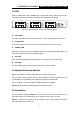
TL-SF2226P+/TL-SL2226P+ Remote Smart Switch User Guide Chapter 4: Explanation of Switch Appearance and the Method of Connecting Switch This chapter covers more details about front panel, rear panel, LED and extension module of the switch. 4.1 Front Panel There are 24 10/100Mbps ports and LED indicators on the front panel of the TL-SF2226P+. 1 3 5 7 9 11 13 15 17 19 21 23 2 4 6 8 10 12 14 16 18 20 22 24 Figure 4-1 Front Panel of the TL-SF2226P+ 4.
TL-SF2226P+/TL-SL2226P+ Remote Smart Switch User Guide 4.3 LED LEDs, including Power LED, 100Mbps LED, Link/Act LED, Slot1, Slot2 and CPU LED, can detect and indicate the state of the switch. More details are as follows. 1 3 5 7 9 11 13 15 17 19 21 23 2 4 6 8 10 12 14 16 18 20 22 24 Figure 4-3 LED Indicators view of TL-SF2226P+ Switch Power LED The power LED will be solid red when power on, or else, check the power connection.
TL-SF2226P+/TL-SL2226P+ Remote Smart Switch User Guide Chapter 5: Installation and the Usage of the Remote Management Software The TL-SF2226P+/TL-SL2226P+ is a smart switch, you can configure it with the remote Management software shipped with the switch, It’s very convenient for you to manage the switch. After install the software under windows OS, you can manage several switches at the same time.
TL-SF2226P+/TL-SL2226P+ Remote Smart Switch User Guide are four steps on configuring the switch. 1) Add 2) Connection 3) Configuration 4) Exit Caution: When you use the switch for the first time, you must reset the IP address and gateway of the switch. The witch default IP address is 192.168.0.100(for more details, please refer to Chapter 5). Here are details on how to use the SSU application.
TL-SF2226P+/TL-SL2226P+ Remote Smart Switch User Guide Figure 5-3 Click Add Group, you can see the dialog. As figure 5-4 Figure 5-4 b) Click the right button at Please Add Group on initialized interface and then pop up a menu, click Add Group.
TL-SF2226P+/TL-SL2226P+ Remote Smart Switch User Guide Figure 5-5 c) Click the add group icon on the tool bar. As figure 5-6. Figure 5-6 2) Add device and node in device group. In device group, you can add device and node, which are just like file and folder. The hiberarchy of node and device of a group are not more than five. If there is the fifth hiberarchy, the fifth hiberachy can only be a device. The device and node can be changed at any time you want.
TL-SF2226P+/TL-SL2226P+ Remote Smart Switch User Guide Open the group you added just now and click the right button on the device name, then there will pop up a menu. As figure 5-7. Figure 5-7 Click Add Dev/ Node, you will see a dialog. As figure 5-8. Figure 5-8 After adding device and node, you can see the interface as figure 5-9.
TL-SF2226P+/TL-SL2226P+ Remote Smart Switch User Guide Figure 5-9 Look at the device icon carefully, if the color of the icon is red, it means that the device can't communicate with the PC. Please check whether the power is on, the twisted pair is well connected and the ping is ok. If all is ok, you can click the save icon to save information of the device. 5.2.2 Connection Now you can connect the device.
TL-SF2226P+/TL-SL2226P+ Remote Smart Switch User Guide The color of the port on the panel is yellow, which means that the port is in connection. If it is red, it means that the port is forbidden to use. If the color of the port frame is red, it’s said that the port is management port. 5.2.3 Configuration If the device is well connected, you can configure the switch now. 5.2.3.1 Conventional Management 1.
TL-SF2226P+/TL-SL2226P+ Remote Smart Switch User Guide Figure 5-11 Current VLAN mode is shown in the combo box, select one mode you want in the combo box and click OK. If you change the VLAN mode, the information of previous VLAN will be lost and the switch will give new default information about VLAN. If the VLAN mode is port VLAN, all ports will be in a VLAN. If the VLAN mode is tag VLAN, all ports will be in a VLAN which tag's value is 1. After Configuring VLAN mode, you can configure VLAN now.
TL-SF2226P+/TL-SL2226P+ Remote Smart Switch User Guide Figure 5-13 Now go back to the main menu->Config->VLAN Config->Config Effect, Only execute this step, the Configuration will be valid. If the VLAN mode is not changed, this menu can't be seen. 2. TRUNK Config TRUNK can transmit net data through a group of ports. The switch looks a TRUNK as a big port regardless of it's composition. Default setting: no TRUNK.
TL-SF2226P+/TL-SL2226P+ Remote Smart Switch User Guide help file. Now go back to main menu->Config->TRUNK Config->Config Effect. Figure 5-15 Only execute this step, the Configuration will be valid. If the TRUNK is not changed, this menu can't be seen. 3. Port Config Click main menu->Config->Port Config or double click a port in the port list box. As figure 5-16. Figure 5-16 Now you can configure each parameter of the port except port priority.
TL-SF2226P+/TL-SL2226P+ Remote Smart Switch User Guide 10HD: 10Mbps, Half-Duplex. 10FD: 10Mbps, Full-Duplex. 100HD: 100Mbps, Half-Duplex. 100FD: 100Mbps, Full-Duplex 2) Flow Control: Disable: The port won't produce Flow Control packets and will discard the Flow Control packets received. Enable: The Switch will negotiate Flow Control on the specified port according to Full-Duplex or Half-Duplex.
TL-SF2226P+/TL-SL2226P+ Remote Smart Switch User Guide Figure 5-17 Now a dialog will be pop up. In the dialog, you should Enable QOS, set high priority and low priority and select a priority class in the list box. For more details, please refer to help file. Figure 5-18 5. Broadcast Storm Control When the Broadcast Storm Control is enabled, it will be valid. Click main menu-> Config-> Broadcast Control and you can configure the Broadcast Storm Control. For more details, please read help file. 6.
TL-SF2226P+/TL-SL2226P+ Remote Smart Switch User Guide you can see the interface as follows. For more details, please refer to help file. Figure 5-19 7. MAC Aging Time Dynamic forwarding table entries, which are made up of the source and destination MAC address and their associated port numbers, are deleted from the table if they are not accessed within the aging time. The aging time can be from 300 to 765 seconds.
TL-SF2226P+/TL-SL2226P+ Remote Smart Switch User Guide Caution: After change, if you can't connect with the switch, you can use RS232 to connect the switch and get the switch IP. 9. Switch VLAN Mode The TL-SF2226P+ can support three VLAN modes, no VLAN, port VLAN and tag VLAN. You can only choose one mode of the three as the current switch VLAN Mode. 10. System Auto Time Click main menu->Config->System Auto Time, you can configure the time in the text box.
TL-SF2226P+/TL-SL2226P+ Remote Smart Switch User Guide Chapter6 TELNET/Out-of-Band Management 6.1 Introduction Through TELNET you can realize Remote Log in to manage the Switch. Out-of-Band Management manages the switch locally through the console port, without occupying the bandwidth. Though TELNET and Out-of-Band have different presentation, their management contents are the same, both of them can be used to configure the switch's characters.
TL-SF2226P+/TL-SL2226P+ Remote Smart Switch User Guide Figure 6-1 The speed of the console port is 19200bps. The data bit is 8 bit. There is not Parity Test and flow control. The Stop bit is 1.Now you will see the interface as follows. Figure 6-2 Input user name and password, the default user name and password are admin, you can change it after logging in.
TL-SF2226P+/TL-SL2226P+ Remote Smart Switch User Guide Figure 6-3 6.3 How to connect TELNET Connect the management workstation to the management port on the switch. You can directly use TELNET command on the command DOS prompt in the Windows Attachment. The parameter following the TELNET command is the IP address of the switch which can be revised adapting to the network. However, when you reuse TELNET to access, the parameter will be the switch's IP address newly set. Here is an example: telnet 222.88.
TL-SF2226P+/TL-SL2226P+ Remote Smart Switch User Guide Input user name and password and you can manage the switch. If you can not log in, check whether the network is working, check whether there is other user who has already logged on. (Only one user can access the switch at one time through TELNET.) 6.4 The interface and operating way of TELNET/Out-of-Band No matter through TELNET or Out-of-Band Management, the users have two rights.
TL-SF2226P+/TL-SL2226P+ Remote Smart Switch User Guide it means that the port is connecting with remote management. You can not shut down the port in order that the remote connection can't be interrupted. You can edit properties of the ports with the space key. If the VLAN type is Tag based VLAN, the PVID can't be visible and can't be edit. As figure 5-6. Figure 6-6 VLAN Management Figure 6-7 VLAN Management includes VLAN Mode, Port Based VLAN and 802.1Q VLAN.
TL-SF2226P+/TL-SL2226P+ Remote Smart Switch User Guide Figure 6-8 Port Based VLAN is as follows. Figure 6-9 Only if current VLAN Mode is Port Based VLAN, you can see this interface, or you will see an error message. If you want to edit VLAN, you can look a trunk as a big port. 802.1Q VLAN is as follows.
TL-SF2226P+/TL-SL2226P+ Remote Smart Switch User Guide Figure 6-10 Only if the VLAN Mode is 802.1Q VLAN, you can see this interface, or you will see an error massage. The configuration method is similar to Port Based VLAN. If the VLAN state is DE, it means the VLAN is invalid. U means untag, T means tag. TRUNK Management TRUNK Management interface as follows: Figure 6-11 Before you enable a TRUNK, you must make the properties of the 4 ports be the same.
TL-SF2226P+/TL-SL2226P+ Remote Smart Switch User Guide rule when they are in the same VLAN. When you enable or disable a TRUNK, the switch will lose the info of static binding address which is relate to the TRUNK or the 4 ports. MAC Table Aging Time MAC Table Aging Time interface is as follows: Figure 6-12 Priority Management Priority Management interface is as follows, when the sate is close, other parameters can't be changed.
TL-SF2226P+/TL-SL2226P+ Remote Smart Switch User Guide Figure 6-14 Press Enter, you will see the interface as follows. Figure 6-15 There are three operations in Static MAC Table, add, delete and edit. The switch can bind 128 MAC at most, including Enable and Disable. Caution: If you configure the Static MAC Table, it will take effect immediately, you needn't save it. Broadcast Storm Broadcast Storm interface is as follows. When Broadcast State is Disable, other parameters can't be changed.
TL-SF2226P+/TL-SL2226P+ Remote Smart Switch User Guide Figure 6-16 2) Network Config Network Config interface is as follows, you can change the switch's IP, gateway, you can not change the switch's MAC address. Figure 6-17 Press w or s key to move cursor, press space to edit the switch's IP address, Default gateway. Input the new IP address and gateway, press enter. If you input a valid IP or gateway, you will get an error message.
TL-SF2226P+/TL-SL2226P+ 3) Remote Smart Switch User Guide Factory Reset This operation will lead to factory set of the switch. All config configured by the user will be valid except network config and user password. The operation will make the switch restart. 4) Change Password The password which can be changed is user password, not administrator password. The length of the password is not more than 7, the password can be null.
TL-SF2226P+/TL-SL2226P+ Remote Smart Switch User Guide Appendix A Technical Specifications TL-SF2226P+ Standards IEEE802.3 10BASE-T IEEE802.3u 100BASE-TX/FX Protocol CSMA/CD Ethernet Data Transfer Ethernet: 10Mbps(half duplex), 20Mbps(full duplex) Fast Ethernet: 100Mbps(half duplex), 200Mpbs(full duplex) Topology Star Network Media (Cable) 10Base-T: UTP category 3, 4, 5 cable (100m) 100Base-TX: UTP category 5 cable (100m) 100Base-FX: 9/125μm or 50/125μm or 62.
TL-SF2226P+/TL-SL2226P+ Remote Smart Switch User Guide Module Slot Two independent module slots Transmits Method Store-and-Forward Power Supply 100-240V ~ 50-60Hz 0.6A (internal universal power supply) Power Consumption Lower than 15 watts Environment Operating temperature: 0℃ ~ 40℃ (32℉~104℉) Storage temperature: -40℃ – 70℃ (-40℉~158℉) Storage humidity: 5% ~ 90% (non-condensing) Dimension(W x H x D) 17.3 in. × 10.2 in. × 1.9 in.