User Guide EAP115-Wall REV1.0.
CONTENTS Chapter 1 Introduction ...................................................................................................................... 1 Chapter 3 Management Mode ........................................................................................................ 4 Chapter 2 Network Topology .......................................................................................................... 2 3.1 Standalone Mode ...............................................................
6.3 Client...................................................................................................................................... 41 6.3.1 6.3.2 Chapter 7 7.1 7.2 LED ON/OFF ........................................................................................................................ 48 Wi-Fi Control ....................................................................................................................... 48 SSH ....................................................
Chapter 1 Introduction Auranet series products provide wireless coverage solutions for small-medium business. They can either work independently as standalone APs or be centrally managed by the EAP Controller software, providing a flexible, richly-functional but easily-configured enterprise-grade wireless network for small and medium business.
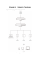
Chapter 2 Network Topology A typical network topology for EAP115-Wall is shown below.
To deploy the EAP in your local network, a DHCP server is required to assign IP addresses to the EAP and clients. Typically, a router acts as the DHCP server. A computer running the EAP Controller software can locate in the same or different subnet with the EAPs.
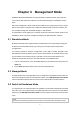
Chapter 3 Management Mode 300Mbps Wireless N Wall-Plate Access Point EAP115-Wall can either work under the control of the EAP Controller software or work independently as a standalone access point. When user establishes a large-scale wireless network, the management of every single EAP in the network is complex and complicated. With the EAP Controller software, you can centrally manage the mass EAPs simply in a web browser. The Standalone mode applies to a relatively small-sized wireless network.
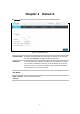
Chapter 4 Network On Network page you can configure the IP address of the standalone EAP. Figure 4-1 Network Page Dynamic/Static: By default, the EAP obtains an IP address from a DHCP server (typically a router). Select Static to configure IP address manually. Fallback IP: If the EAP fails to get a dynamic IP address from a DHCP server within ten seconds, the fallback IP will work as the IP address of the device.
Chapter 5 Wireless Wireless page, consisting of Wireless Settings, Portal, MAC Filtering, Scheduler, QoS and Rogue AP Detection, is shown below.
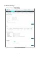
5.1 Wireless Settings Following is the page of Wireless Settings.
TIPS: Proceed to the following chapter for information on configuring the wireless network of the EAP. 5.1.1 Wireless Basic Settings Figure 5-3 Wireless Basic Settings 2.4GHz Wireless Radio: Check the box to enable 2.4GHz Wireless Radio. Wireless Mode: Select the protocol standard for the wireless network. Channel Width: Select the channel width of this device. Wireless network created by the EAP work within 2.4GHz. The EAP supports 802.11b/g/n, 802.11b/g, and 802.11n standards.
Channel: Select the channel used by this device to improve wireless performance. 1/2412MHz means the Channel is 1 and the frequency is 2412MHz. By default, channel is automatically selected. Tx Power(EIRP): Enter the transmit power value. By default, the value is 20. If the maximum transmit power is set to be larger than local regulation allows, the maximum Tx power regulated will be applied in actual situation. NOTE: In most cases, it is unnecessary to select maximum transmit power.
SSID Name: Enter up to 32 characters as the SSID name. Wireless VLAN ID: Set a VLAN ID (ranges from 0 to 4094) for the wireless network. Wireless networks with the same VLAN ID are grouped to a VLAN. SSID Broadcast: Enable this function, AP will broadcast its SSID to hosts in the surrounding environment, as thus hosts can find the wireless network identified by this SSID. If SSID Broadcast is not enabled, hosts must enter the AP’s SSID manually to connect to this AP.
Figure 5-5 Security Mode-WEP Type: Select the authentication type for WEP. Auto: The default setting is Auto, which can select Open System or Shared Key automatically based on the wireless station's capability and request. Open System: After you select Open System, clients can pass the authentication and associate with the wireless network without password. However, correct password is necessary for data transmission.
WPA-Enterprise Based on RADIUS server, WPA-Enterprise can generate different passwords for different users and it is much safer than WPA-PSK. However, it costs much to maintain and is more suitable for enterprise users. At present, WPA-Enterprise has two versions: WPA-PSK and WPA2-PSK. Figure 5-6 Security Mode_WPA-Enterprise Version: Select one of the following versions: Auto: Select WPA-PSK or WPA2-PSK automatically based on the wireless station's capability and request.
WPA-PSK Based on pre-shared key, security mode WPA-PSK is characterized by high security and simple configuration, which suits for common households and small business. WPA-PSK has two versions: WPA-PSK and WPA2-PSK. Figure 5-7 Security Mode_WPA-PSK Version: Auto: Select WPA-PSK or WPA2-PSK automatically based on the wireless station's capability and request. WPA-PSK: Pre-shared key of WPA-PSK. WPA2-PSK: Pre-shared key of WPA2-PSK.
Beacon Interval: Beacons are transmitted periodically by the device to announce the presence of a wireless network for the clients. Beacon Interval value determines the time interval of the beacons sent by the device. You can specify a value from 40 to 100. The default value is 100 milliseconds. DTIM Period: This value indicates the number of beacon intervals between successive Delivery Traffic Indication Messages (DTIMs) and this number is included in each Beacon frame.
Maximum Associated Clients: Enter the number of clients to be allowed for connection to the EAP. The number ranges from 1 to 99. 5.2 Portal Portal authentication enhances the network security by providing authentication service to the clients that just need temporary access to the wireless network. Such clients have to log into a web page to establish verification, after which they will access the network as guests.
NOTE: To apply Portal in a wireless network, please go to Wireless→Wireless Settings→SSIDs to enable Portal of a selected SSID. 5.2.1 Portal Configuration Three authentication types are available: No Authentication, Local Password and External RADIUS Server. 1. No Authentication:Users are required to finish only two steps: agree with the user protocol and click the Login button. 2. Local Password:Users are required to enter the preset password, which are saved in the EAP. 3.
Authentication Type: Select No Authentication. Authentication Timeout: After successful verification, an authentication session is established. Authentication Timeout decides the active time of the session. Within the active time, the device keeps the authentication session open with the associated client. To reopen the session, the client needs to log in the web authentication page and enter the user name and password again once authentication timeout is reached.
Local Password Figure 5-12 Portal Configuration_Local Password Authentication Type: Select Local Password. Password: Enter the password for local authentication. Please refer to No Authentication to configure Authentication Timeout, Redirect, Redirect URL, and Portal Customization. External RADIUS Server External RADIUS Server provides two types of portal customization: Local Web Portal and External Web Portal.
1. Local Web Portal Figure 5-13 Portal Configuration_External RADIUS Server_Local Web Portal Authentication Type: Select External RADIUS Server. RADIUS Server IP: Enter the IP address of the RADIUS server. Port: Enter the port for authentication service. RADIUS Password: Enter the shared secret of RADIUS server to log in to the RADIUS server. Please refer to No Authentication to configure Authentication Timeout, Redirect, Redirect URL, and Portal Customization.
2. External Web Portal Figure 5-14 Portal Configuration_External RADIUS Server_External Web Portal Authentication Type: Select External RADIUS Server. RADIUS Server IP: Enter the IP address of the RADIUS server. Port: Enter the port for authentication service. RADIUS Password: Enter the shared secret of RADIUS server to log in to the RADIUS server. Portal Customization: Select External Web Portal.
Click to add a new authentication policy and configure its parameters. Figure 5-16 Configure Free Authentication Policy Policy Name: Source Range: Enter a policy name. IP Destination IP Range: Enter the source IP address and subnet mask of the clients who can enjoy the free authentication policy. Leaving the field empty means all IP addresses can access the specific resources. Enter the destination IP address and subnet mask for free authentication policy.
Click the button OK in Figure 5-16 and the policy is successfully added as Figure 5-17 shows. Figure 5-17 Add Free Authentication Policy Here is the explanation of Figure 5-17: The policy name is Policy 1. Clients with IP address range 192.168.2.0/24 are able to visit IP range 10.10.10.0/24. Policy 1 is enabled. Click to edit the policy. Click to delete the policy. 5.3 MAC Filtering MAC Filtering uses MAC addresses to determine whether one host can access the wireless network.
Settings Enable Filtering: MAC Check the box to enable MAC Filtering. Station MAC Group Follow the steps below to add MAC groups. Step 1: Click , two tables will be shown. Figure 5-19 Station MAC Group Step 2: Click and fill in a name for the MAC group. Figure 5-20 Add a Group Step 3: Select one MAC group, click and input the MAC address you want to organize into this group.
Figure 5-21 Add a Group Member Click in Modify column to edit the MAC group name or MAC address. Click delete the MAC group or group member. to MAC Filtering Association Figure 5-22 MAC Filtering Association SSID Name: Displays the SSID of the wireless network. Band: Displays the frequency band the wireless network operates at. MAC Group Name: Select a MAC group from the drop-down list to allow or deny its members to access the wireless network.
5.4 Scheduler Scheduler allows you to configure rules with specific time interval for radios to operate, which automates the enabling or disabling of the radio. Figure 5-23 Scheduler Page Settings Scheduler: Check the box to enable Scheduler. Association Mode: Select Associated with SSID/AP, you can perform configurations on the SSIDs/AP. The display of Scheduler Association is based on your option here. Scheduler Profile Configuration Follow the steps below to add rules.
Figure 5-24 Scheduler Profile Configuration Step 2: Click and input a profile name for the rule. Figure 5-25 Add a Profile Step 3: Select one profile, and click rule.
Scheduler Association This zone will display different contents based on your selection of association mode in Settings. 1. Associated with SSID Figure 5-27 Scheduler Association_Associated with SSID SSID Name: Displays the SSID of the standalone AP. Band: Displays the frequency band which the wireless network operates at. Profile Name: Select a profile name from the drop-down list. Profile name is configured in Scheduler Profile Configuration.
5.5 QoS The EAP supports Quality of Service (QoS) to prioritize voice and video traffic over other traffic types. In normal use, we recommend you keep the default values for the EAP devices and station EDCA (Enhanced Distributed Channel Access). Figure 5-29 QoS Page Wi-Fi Multimedia (WMM): By default, WMM is enabled. After WMM is enabled, the device has the QoS function to guarantee the transmission of audio and video packets with high priority.
5.5.1 AP EDCA Parameters AP Enhanced Distributed Channel Access (EDCA) parameters affect traffic flowing from the EAP device to the client station. Figure 5-30 AP EDCA Parameters Queue: Queue displays the transmission queue. By default, the priority from high to low is Data 0, Data 1, Data 2, and Data 3. The priority may be changed if you reset the EDCA parameters. Data 0 (Voice)—Highest priority queue, minimum delay.
Maximum Burst The Maximum Burst is an AP EDCA parameter that applies only to traffic flowing from the EAP devices to the client station. This value specifies (in milliseconds) the maximum burst length allowed for packet bursts on the wireless network. A packet burst is a collection of multiple frames transmitted without header information. The decreased overhead results in higher throughput and better performance. The valid values are multiples of 32 between 0 and 8192. 5.5.
Minimum Contention Window: A list to the algorithm that determines the initial random backoff wait time (window) for retry of a transmission. This value cannot be higher than the value for the Maximum Contention Window. Maximum Contention The upper limit (in milliseconds) for the doubling of the random backoff value. This doubling continues until either the data frame is sent or the Maximum Contention Window size is reached.
Figure 5-32 Rogue AP Detection Page 5.6.1 Settings Figure 5-33 Enable Rogue AP Detection Rogue AP Detection: Check the box to enable Rogue AP Detection, then click Save. 5.6.2 Rogue AP List detected Information about the detected rogue APs is displayed in the list. By default, the status of the detected rogue AP is unknown. You can click Known in Action column to move the AP to the Trusted AP List.
Figure 5-34 Detected Rogue AP List Click to scan rogue APs. Make sure you have enabled Rogue AP Detection and saved the setting before you click the button. Action: Click Known to move the AP to the Trusted AP List. After the configurations are saved, the moved AP will not be displayed in the Detected Rogue AP List. MAC: The MAC address of the rogue AP. SSID: The SSID of the rogue AP. Band: Displays the frequency band which the wireless network of the rogue AP operates at.
MAC: The MAC address of the trusted AP. SSID: The SSID of the trusted AP. Band: Displays the frequency band which the wireless network of the trusted AP operates at. Channel: The channel on which the trusted AP is currently broadcasting. Security: Displays the enabling or disabling of the security mode of the wireless network. 5.6.4 Download/Backup Trusted AP List You can import a list of trusted APs from a saved list which is acquired from another AP or created from a text file.
Chapter 6 Monitoring On Monitoring page, you can monitor the network running status and statistics based on AP, SSID and Client. 6.1 AP AP List on the Monitoring page displays the device name, its MAC address and the number of clients. Below the AP List the AP’s detailed information will be shown, including Device Information, Wireless Settings, LAN Information, Client, LAN Traffic and Radio Traffic. Figure 6-1 AP Monitoring 6.1.
Device Name: Displays the device name. MAC: Displays the MAC address of the EAP. Num of Clients: Displays the number of clients connected to the EAP. Device Information Figure 6-3 Device Information Device Name: Displays the device name. Device Model: Displays the model of the device. Firmware Version: Displays the firmware version of the device. If you want to upgrade the firmware, please refer to 8.5 Firmware Upgrade. System Time: Displays the system time of the device.
Wireless Settings Figure 6-4 Wireless Settings Channel/Frequency: Displays the channel number and the operating frequency. If you want to change them, please refer to 5.1.1 Wireless Basic Settings. Channel Width: Displays the spectral width of the radio channel used by the device. If you want to change it, refer to 5.1.1 Wireless Basic Settings. IEEE802.11 Mode: Displays the radio standard used for operation of your device. If you want to change it, refer to 5.1.1 Wireless Basic Settings.
LAN Port1/ LAN Port2: Displays the maximum transmission rate and duplex mode (half-duplex or full-duplex) of the port. Client Figure 6-6 Client MAC: Displays the MAC address of the client of the AP selected in AP List. SSID: Displays the SSID the client is connected to. SNR(dB): Signal to Noise Ratio, the power ratio between the received wireless signal strength and the environmental noise strength. The bigger the value of SNR is, the better network performance the device provides.
Rx/Tx Bytes: Displays the total amount of data (in bytes) received/sent on the LAN port. Rx/Tx Dropped Packets: Displays the total amount of dropped packets received/sent on the LAN port. Rx/Tx Errors: Displays the total amount of error packets received/sent on the LAN port. Radio Traffic Click Radio Traffic and you can monitor the data transmission status of the wireless network. Figure 6-8 Radio Traffic Rx/Tx Packets: Displays the total amount of packets received/sent by the wireless network.
6.2 SSID Figure 6-9 SSID Monitoring 6.2.1 SSID List In SSID List you can monitor the related parameters of the wireless network. Figure 6-10 SSID List SSID Name: Displays the SSID name. If you want to modify it, please refer to 5.1.2 SSIDs. VLAN ID: Displays the VLAN which the SSID belongs to. If you want to change the VLAN ID, please refer to 5.1.2 SSIDs. Num of Clients: Displays the number of clients connected to the SSID. If you want to get more information about these clients, please refer to 5.
MAC Filtering: Displays the enabling or disabling of MAC Filtering. If you want to modify it, please refer to 5.1.2 SSIDs. Isolation: Displays the enabling or disabling of SSID Isolation. If you want to modify it, please refer to 5.1.2 SSIDs. Down(Byte): Displays the throughput of the downstream data. Up(Byte): Displays the throughput of the upstream data. 6.3 Client From User List, you can monitor the status of all the clients connected to the EAP including those who are authenticated.
Band: Displays the band the client is in. Access Point: Displays the name of the device to which the client is connected. SSID: Displays the SSID the client is connected to. SNR(dB): Signal to Noise Ratio, the power ratio between the received wireless signal strength and the environmental noise strength. The bigger the value of SNR, the better network performance the device provides. CCQ(%): Displays the wireless Client Connection Quality (CCQ).
CCQ(%): Displays the Client Connection Quality (CCQ) of the authenticated client. CCQ refers to the ratio of current effective transmission bandwidth and the theoretically maximum available bandwidth. CCQ reflects the actual link condition. Rate(Mbps): Displays the data rate at which the authenticated client transmits wireless packets. Down(Byte): Displays the throughput of the downstream data. Up(Byte): Displays the throughput of the upstream data.
Chapter 7 Management Management page is mainly used for device management and maintenance. 7.1 System Log System log records information about hardware, software as well as system issues and monitors system events. With the help of system log, you can get informed of system running status and detect the reasons for failure. Following is the page of System Log . Figure 7-1 System Log Page 7.1.1 Log List From Log List you can view detailed information about hardware, software, system issues and so on.
Figure 7-2 Log List 7.1.2 Log Settings You can choose the way to receive system logs in Log Settings zone, where these parameters can be configured: Enable Auto Mail, Enable Server and Enable Nvram. Figure 7-3 Log Settings Enable Auto Mail If Auto Mail Feature is enabled, system logs will be sent to a mailbox. The following content will be shown. Figure 7-4 Enable Auto Mail From: Enter the sender’s email address.
To: Enter the recipient’s email address, which will receive the system logs. SMTP Server: Enter the IP address of the SMTP server. Enable Authentication: Generally users are required to log in to the SMTP server by entering user name and password. Time Mode: Password: Enter the password of the sender’s email address. Confirm Password: Enter the password again for confirmation. System logs can be sent at specific time or time interval. User Name: Enter the sender’s email address.
Figure 7-6 Web Server Page HTTPS: HTTPS (Hypertext Transfer Protocol Secure) is enabled by default. Secure Server Port: Designate a secure server port for web server in HTTPS mode. By default the port is 443. Server Port: Designate a server port for web server in HTTP mode. By default the port is 80. Session Timeout: Set the session timeout time. If you do nothing with the web management page within the timeout time, the system will log out automatically.
Figure 7-7 Management Access Page MAC Authentication: Check the box to enable MAC Authentication. After MAC Authentication is enabled, only the PCs in MAC address list can log in the device’s web management page. By default this function is disabled. All PCs in LAN can log in and manage the device. MAC1~MAC4: Enter the MAC addresses of the PCs which are authorized to log in the device. 7.4 LED ON/OFF LED ON/OFF function allows you to control the LED.
Figure 7-9 Wi-Fi Control With the Wi-Fi Control enabled, you can turn on/off the Wi-Fi and LED simultaneously by pressing the button on the front panel. Note: You can enable Wi-Fi Control feature only when the LED ON/OFF is enabled. 7.6 SSH This device supports the SSH Server function that allows users to login and manage it through SSH connection on the SSH client software. SSH (Secure Shell) is a security protocol established on application and transport layers.
SSH Login: Check the box to enable SSH Server. By default, it is disabled. 7.7 Management VLAN Management VLAN provides a safer way for you to manage the EAP. With Management VLAN enabled, only the hosts in the management VLAN can manage the EAP. Since most hosts cannot process VLAN TAGs, connect the management host to the network via a switch, and set up correct VLAN settings for the switches on the network to ensure the communication between the host and the EAP in the management VLAN.
Following is the page of SNMP. Figure 7-12 SNMP Page SNMP Agent: Enable SNMP Agent and the SNMP Agent will collect the information of this device and respond to information requests from one or more management systems. SysContact: Enter the textual identification of the contact person for this managed node. SysName: Enter an administratively-assigned name for this managed node. SysLocation: Enter the physical location of this managed node.
Set Source: Defines the IP address (for example, 10.10.10.1) or subnet for management systems that can serve as Set Community to read and write the SNMP information of this device. The format of subnet is “IP address/bit” (such as 10.10.10.0/24). The default is 0.0.0.0, which means all hosts can read and write the SNMP information of this device. NOTE: Defining community can allow management systems in the same community to communicate with the SNMP Agent.
Chapter 8 System System page is mainly used to configure some basic information like user account and time, and realize functions including reboot, reset, backup, restore and upgrade the device. 8.1 User Account You can change the username and password to protect your device from unauthorized login. We recommend that you change the default user password on the very first system setup.
the system time, configure the system to acquire its time settings from a preconfigured NTP server or synchronize the system time with the PC’s clock. The device supports DST (Daylight Saving Time). Figure 8-2 Time Settings 8.2.1 Time Settings Figure 8-3 Time Settings Click the button and the device will obtain GMT time from NTP server. IP address of the NTP server has to be filled in.
Click the button and save the configuration, your PC’s time will be obtained as the device’s system time. Time zone: Select your local time zone from the drop-down list. Date: Set the current date, in format MM/DD/YYYY. For example, for November 25, 2014, enter 11/25/2014 in the field. Time: Specify the device’s time. Select the number from the dropdown list in time format HH/MM/SS.
Predefine Country: Select a predefined DST configuration. Europe is the predefined country by default. USA: Second Sunday in March, 02:00 ~ First Sunday in November, 02:00 European: Last Sunday in March, 01:00 ~ Last Sunday in October, 01:00 Australia: First Sunday in October, 02:00 ~ First Sunday in April, 03:00 New Zealand: Last Sunday in September, 02:00 ~ First Sunday in April, 03:00 Recurring Mode Figure 8-6 Recurring Mode Mode: Select Recurring Mode.
8.3 Reboot/Reset Figure 8-8 Reboot & Reset Click Reboot to restart the device. Click Reset to restore the device to factory default settings. 8.4 Backup & Restore Figure 8-9 Backup & Restore You can save the current configuration of the EAP as a backup file and restore the configuration via a backup file. To prevent the settings from being lost, we recommend that you back up the settings before you upgrade the device or upload a new configuration file.
8.5 Firmware Upgrade Figure 8-10 Firmware Upgrade Please log in http://www.tp-link.com/ to download the latest system file. Click Browse to choose the firmware file. Click Upgrade to upgrade the devices. NOTE: 1. Please select the proper software version that matches your hardware to upgrade. 2. To avoid damage, please do not turn off the device while upgrading. 3. After upgrading, the device will reboot automatically.
COPYRIGHT & TRADEMARKS Specifications are subject to change without notice. is a registered trademark of TP-Link Technologies CO., LTD. Other brands and product names are trademarks or registered trademarks of their respective holders. No part of the specifications may be reproduced in any form or by any means or used to make any derivative such as translation, transformation, or adaptation without permission from TP-Link Technologies CO., LTD. Copyright © 2016 TP-Link Technologies CO., LTD.
FCC STATEMENT This equipment has been tested and found to comply with the limits for a Class B digital device, pursuant to part 15 of the FCC Rules. These limits are designed to provide reasonable protection against harmful interference in a residential installation. This equipment generates, uses and can radiate radio frequency energy and, if not installed and used in accordance with the instructions, may cause harmful interference to radio communications.
provide a separation distance of at least 20 cm from all persons and must not be colocated or operating in conjunction with any other antenna or transmitter.” RF Exposure Information This device meets the EU requirements (1999/5/EC Article 3.1a) on the limitation of exposure of the general public to electromagnetic fields by way of health protection. The device complies with RF specifications when the device used at 20 cm from your body. CE Mark Warning This is a class B product.
Industry Canada Statement CAN ICES-3 (B)/NMB-3(B) Korea Warning Statements 당해 무선설비는 운용중 전파혼신 가능성이 있음. Продукт сертифіковано згідно с правилами системи УкрСЕПРО на відповідність вимогам нормативних документів законодавчими актами України.
BSMI Notice 安全諮詢及注意事項 請使用原裝電源供應器或只能按照本產品注明的電源類型使用本產品。 清潔本產品之前請先拔掉電源線。請勿使用液體、噴霧清潔劑或濕布進行清潔。 注意防潮,請勿將水或其他液體潑灑到本產品上。 插槽與開口供通風使用,以確保本產品的操作可靠並防止過熱,請勿堵塞或覆蓋開口。 請勿將本產品置放於靠近熱源的地方。除非有正常的通風,否則不可放在密閉位置中。 請不要私自打開機殼,不要嘗試自行維修本產品,請由授權的專業人士進行此項工作。 Explanation of the symbols on the product label Symbol Explanation Class II equipment DC voltage RECYCLING This product bears the selective sorting symbol for Waste electrical and electronic equipment (WEEE).
COPYRIGHT & TRADEMARKS Specifications are subject to change without notice. is a registered trademark of TP-Link Technologies CO., LTD. Other brands and product names are trademarks or registered trademarks of their respective holders. No part of the specifications may be reproduced in any form or by any means or used to make any derivative such as translation, transformation, or adaptation without permission from TP-Link Technologies CO., LTD. Copyright © 2016 TP-Link Technologies CO., LTD.
Any changes or modifications not expressly approved by the party responsible for compliance could void the user’s authority to operate the equipment. Note: The manufacturer is not responsible for any radio or TV interference caused by unauthorized modifications to this equipment. Such modifications could void the user’s authority to operate the equipment. FCC RF Radiation Exposure Statement: This equipment complies with FCC RF radiation exposure limits set forth for an uncontrolled environment.
Déclaration d'exposition aux radiations: Cet équipement est conforme aux limites d'exposition aux rayonnements IC établies pour un environnement non contrôlé. Cet équipement doit être installé et utilisé avec un minimum de 20 cm de distance entre la source de rayonnement et votre corps. Canadian Compliance Statement This device complies with Industry Canada license-exempt RSSs.
Safety Information When product has power button, the power button is one of the way to shut off the product; When there is no power button, the only way to completely shut off power is to disconnect the product or the power adapter from the power source. Don’t disassemble the product, or make repairs yourself. You run the risk of electric shock and voiding the limited warranty. If you need service, please contact us. Avoid water and wet locations.
Explanation of the symbols on the product label Symbol Explanation Class II equipment DC voltage RECYCLING This product bears the selective sorting symbol for Waste electrical and electronic equipment (WEEE). This means that this product must be handled pursuant to European directive 2012/19/EU in order to be recycled or dismantled to minimize its impact on the environment.