User Guide MC100CM MC110CS Fast Ethernet Media Converter MC111CS MC112CS WDM Fast Ethernet Media Converter Rev: 2.0.
COPYRIGHT & TRADEMARKS Specifications are subject to change without notice. is a registered trademark of TP-LINK TECHNOLOGIES CO., LTD. Other brands and product names are trademarks or registered trademarks of their respective holders. No part of the specifications may be reproduced in any form or by any means or used to make any derivative such as translation, transformation, or adaptation without permission from TP-LINK TECHNOLOGIES CO., LTD. Copyright © 2013 TP-LINK TECHNOLOGIES CO., LTD.
FCC STATEMENT This equipment has been tested and found to comply with the limits for a Class A digital device, pursuant to part 15 of the FCC Rules. These limits are designed to provide reasonable protection against harmful interference when the equipment is operated in a commercial environment. This equipment generates, uses, and can radiate radio frequency energy and, if not installed and used in accordance with the instruction manual, may cause harmful interference to radio communications.
IC STATEMENT This Class A digital apparatus complies with Canadian ICES-003. Cet appareil numérique de la classe A est conforme à la norme NMB-003 du Canada.
CONTENTS Package contents ...........................................................................1 Chapter 1 Introduction ...............................................................2 1.1 Overview of the Converter ..........................................2 1.2 Conventions ................................................................3 1.3 Features......................................................................3 1.4 Connectors and Network Cables Supported...............3 1.
Package contents The following items should be found in your package: ¾ One Converter ¾ One AC-DC Power Adapter (DC9V/600mA) ¾ One User Guide ¾ One Purchasing Guide Note: Make sure that the package contains the above items. If any of the listed items are damaged or missing, please contact your distributor.
Chapter 1 Introduction Thank you for choosing the MC100CM/MC110CS Fast Ethernet Media Converters or the MC111CS/MC112CS WDM Fast Ethernet Media Converters! 1.1 Overview of the Converter MC100CM and MC110CS are Fast Ethernet Media Converters.
1.2 Conventions The Converter mentioned in this guide stands for Fast Ethernet Media Converters or the WDM Fast Ethernet Media Converters without any explanation. The TP port mentioned in this User Manual stands for the TX port without any explanations. Note: The four converters are sharing this User Guide. The differences between them please refer to the table of the section 1.4. 1.3 Features ¾ Complies with 802.3u 10/100Base-TX, 100Base-FX standards.
¾ Connectors: RJ-45, SC. ¾ Network Cables: Cat.5 Twisted-Pair (below abbreviated as TP), 9/125um Single-mode fiber and 50/125, 62.5/125um Multi-mode fiber. Transmission Transmission Output Center Distance Media Wavelength Model NO. Interface MC100CM RJ45--SC 2km Multi-mode Fiber, TP 1310nm MC110CS RJ45--SC 20km Single-mode Fiber, TP 1310nm MC111CS RJ45--SC 20km Single-mode Fiber, TP 1550nmTX 1310nmRX MC112CS RJ45--SC 20km Single-mode Fiber, TP 1310nmTX 1550nmRX 1.
Name PWR LFP Status Power on Off Power off On The Link Fault Pass Through function enable. Off The Link Fault Pass Through function disable. On FX Link/Act SPD FDX/Col TP Link/Act Indication On Flashing There’s a valid link. The converter is receiving or transmitting data from the fiber optic connector. Off There’s no valid link. On The TP port is connected to 100Base-Tx Off The TP port is connected to 10Base-Tx device or no connection.
1.5.2 Switch ¾ TP_AUTO: The TP port operates in Auto-Negotiation mode; ¾ TP_DIS: The TP port operates in FORCE mode; ¾ TP_100M: The TP port operates in 100Base-Tx; ¾ TP_10M: The TP port operates in 10Base-T mode; ¾ TP_FDX: The TP port operates in Full-Duplex mode; ¾ TP_HDX: The TP port operates in Half-Duplex mode; ¾ LFP_OFF: The Link Fault Pass Through function disable; ¾ LFP_ON: The Link Fault Pass Through function enable.
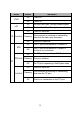
The Mode Of The Device Switch TP:AUTO; LFP ON TP_AUTO, TP_100M, TP_FDX, LFP_ON TP:AUTO; LFP OFF TP_AUTO, TP_100M, TP_FDX, LFP_OFF TP:FORCE,100M,FULL; LFP ON TP_DIS, TP_100M, TP_FDX, LFP_ON TP:FORCE,100M,FULL; LFP OFF TP_DIS, TP_100M, TP_FDX, LFP_OFF TP:FORCE,100M, HALF; LFP ON (TP_DIS or TP_AUTO), TP_100M, TP_HDX, LFP_ON TP:FORCE,100M, HALF; LFP OFF (TP_DIS or TP_AUTO), TP_100M, TP_HDX, LFP_OFF TP:FORCE,10M,FULL; LFP ON TP_DIS, TP_10M, TP_FDX, LFP_ON TP:FORCE,10M,FULL; LFP OFF TP_DIS, TP_10
With the Link Fault Pass Through function enabled (optional with switch LFP), TP port and FX port of the same converter will inform each other the fault link status so that when one side of the link fails, the other side will force the link to shut down as soon as noticed. The procedure will be illustrated as shown below. If link fail happens on TP port (A), the FX port (A) sends non-idle pattern to notice the FX port (B).
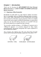
Chapter 2 Installation Guide 2.1 Fast Ethernet Media Converter 1. The SC fiber connector of MC100CM transmits/receives data by 1310nm short wave laser on multi-mode fiber. 2. The SC fiber connector of MC110CS transmits/receives data by 1310nm short wave laser on single-mode fiber. Transmits and receives data on different fibers Note: You have to use either two MC100CM connectors or two MC110CS connectors to cooperate. 2.2 WDM Fast Ethernet Media Converter 1.
2. The SC fiber connector of MC112CS transmits data by 1310nm short wave laser while receives data by 1550nm short wave laser on one single-mode fiber. Transmits and receives data on the same fiber Note: You have to use MC111CS and MC112CS at the same time to cooperate.
Chapter 3 Configuration In order to achieve the aim of effectively expanding a Fast Ethernet network, you can use the converter like the following examples: 1. Place two converters back to back between the following end devices. Note: You should use two MC100CM Media Converters or two MC110CS Media Converters, or one MC111CS and one MC112CS to expand your network. Error will occur when you use other ways. 2.
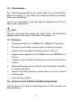
3.1 Installation Procedure Use a fiber cable to connect two converters, or connect a converter with a 100Base-FX Device. 1. Connection of a Converter and a 10/100Base-TX Device (HUB or Switch). • Make sure that the length of the Cat.5 twisted pair cable between the 10/100Base-TX device and the converter is less than 100 meters. • Connect one end of the Cat.5 twisted pair cable to the RJ45 jack on the converter and the other end of the cable to the RJ45 jack on the 10/100Base-TX device. 2.
Appendix: Specifications Standard IEEE 802.3 / IEEE 802.3u Connector 1 SC fiber optic; 1 RJ45 jack Cat.5 Twisted Pair:100m Max.