User Guide MC100CM MC110CS Fast Ethernet Media Converter MC111CS MC112CS WDM Fast Ethernet Media Converter REV2.1.
COPYRIGHT & TRADEMARKS Specifications are subject to change without notice. is a registered trademark of TP-LINK TECHNOLOGIES CO., LTD. Other brands and product names are trademarks or registered trademarks of their respective holders. No part of the specifications may be reproduced in any form or by any means or used to make any derivative such as translation, transformation, or adaptation without permission from TP-LINK TECHNOLOGIES CO., LTD. Copyright © 2015 TP-LINK TECHNOLOGIES CO., LTD.
FCC STATEMENT This equipment has been tested and found to comply with the limits for a Class A digital device, pursuant to part 15 of the FCC Rules. These limits are designed to provide reasonable protection against harmful interference when the equipment is operated in a commercial environment. This equipment generates, uses, and can radiate radio frequency energy and, if not installed and used in accordance with the instruction manual, may cause harmful interference to radio communications.
Продукт сертифіковано згідно с правилами системи УкрСЕПРО на відповідність вимогам нормативних документів та вимогам, що передбачені чинними законодавчими актами України. Safety Information When product has power button, the power button is one of the way to shut off the product; When there is no power button, the only way to completely shut off power is to disconnect the product or the power adapter from the power source. Don’t disassemble the product, or make repairs yourself.
●請勿將本產品置放於靠近熱源的地方。除非有正常的通風,否則不 可放在密閉位置中。 ●請不要私自打開機殼,不要嘗試自行維修本產品,請由授權的專業 人士進行此項工作。 此為甲類資訊技術設備,于居住環境中使用時,可能會造成射頻擾動, 在此種情況下,使用者會被要求採取某些適當的對策。 This product can be used in the following countries: AT BG BY CA CZ DE DK EE ES FI FR GB GR HU IE IT LT LV MT NL NO PL PT RO RU SE SK TR UA US
CONTENTS Package contents ........................................................................... 1 Chapter 1 Introduction ............................................................... 2 1.1 Overview of the Converter .......................................... 2 1.2 Conventions ................................................................ 3 1.3 Features ...................................................................... 3 1.4 Connectors and Network Cables Supported............... 3 1.
Package contents The following items should be found in your package: One Converter One AC-DC Power Adapter (DC9V/600mA) One User Guide One Purchasing Guide Note: Make sure that the package contains the above items. If any of the listed items are damaged or missing, please contact your distributor.
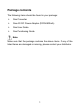
Chapter 1 Introduction Thank you for choosing the MC100CM/MC110CS Fast Ethernet Media Converters or the MC111CS/MC112CS WDM Fast Ethernet Media Converters! 1.1 Overview of the Converter MC100CM and MC110CS are Fast Ethernet Media Converters.
1.2 Conventions The Converter mentioned in this guide stands for Fast Ethernet Media Converters or the WDM Fast Ethernet Media Converters without any explanations. The TP port mentioned in this User Manual stands for the TX port without any explanations. Note: The four converters are sharing this User Guide. Their differences are in the table in Section 1.4. 1.3 Features Complies with 802.3u 10/100Base-TX, 100Base-FX standards. Provides one SC fiber connector and one RJ-45 connector.
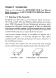
Connectors: RJ-45, SC. Network Cables: Cat.5 Twisted-Pair (below abbreviated as TP), 9/125um Single-mode fiber and 50/125, 62.5/125um Multi-mode fiber. Transmission Transmission Output Center Distance Media Wavelength Model NO. Interface MC100CM RJ45--SC 2km Multi-mode Fiber, TP 1310nm MC110CS RJ45--SC 20km Single-mode Fiber, TP 1310nm MC111CS RJ45--SC 20km Single-mode Fiber, TP 1550nmTX 1310nmRX MC112CS RJ45--SC 20km Single-mode Fiber, TP 1310nmTX 1550nmRX 1.
Name PWR LFP FX Link/Act SPD Status Power on. Off Power off. On The Link Fault Pass Through function enable. Off The Link Fault Pass Through function disable. On There’s a valid link. Flashing TP Link/Act The converter is receiving or transmitting data from the fiber optic connector. Off There’s no valid link. On The TP port is connected to 100Base-Tx Off The TP port is connected to 10Base-Tx device or no connection.
1.5.2 Switch TP_AUTO: The TP port operates in Auto-Negotiation mode; TP_DIS: The TP port operates in FORCE mode; TP_100M: The TP port operates in 100Base-Tx; TP_10M: The TP port operates in 10Base-T mode; TP_FDX: The TP port operates in Full-Duplex mode; TP_HDX: The TP port operates in Half-Duplex mode; LFP_OFF: The Link Fault Pass Through function is disabled; LFP_ON: The Link Fault Pass Through function is enabled.
The Mode Of The Device Switch TP:AUTO; LFP ON TP_AUTO, TP_100M, TP_FDX, LFP_ON TP:AUTO; LFP OFF TP_AUTO, TP_100M, TP_FDX, LFP_OFF TP:FORCE,100M,FULL; LFP ON TP_DIS, TP_100M, TP_FDX, LFP_ON TP:FORCE,100M,FULL; LFP OFF TP_DIS, TP_100M, TP_FDX, LFP_OFF TP:FORCE,100M, HALF; LFP ON (TP_DIS or TP_AUTO), TP_100M, TP_HDX, LFP_ON TP:FORCE,100M, HALF; LFP OFF (TP_DIS or TP_AUTO), TP_100M, TP_HDX, LFP_OFF TP:FORCE,10M,FULL; LFP ON TP_DIS, TP_10M, TP_FDX, LFP_ON TP:FORCE,10M,FULL; LFP OFF TP_DIS, TP_10
With the Link Fault Pass Through function enabled (optional with switch LFP), TP port and FX port of the same converter will inform each other the fault link status so that when one side of the link fails, the other side will force the link to shut down as soon as noticed. The procedure will be illustrated as shown below. If link fail happens on TP port (A), the FX port (A) sends non-idle pattern to notice the FX port (B).
Chapter 2 Installation Guide 2.1 Fast Ethernet Media Converter 1. The SC fiber connector of MC100CM transmits/receives data by 1310nm short wave laser on multi-mode fiber. 2. The SC fiber connector of MC110CS transmits/receives data by 1310nm short wave laser on single-mode fiber. Transmits and receives data on different fibers Note: You have to use either two MC100CM connectors or two MC110CS connectors to cooperate. 2.2 WDM Fast Ethernet Media Converter 1.
2. The SC fiber connector of MC112CS transmits data by 1310nm short wave laser while receives data by 1550nm short wave laser on one single-mode fiber. Transmits and receives data on the same fiber Note: You have to use MC111CS and MC112CS at the same time to cooperate.
Chapter 3 Configuration In order to effectively expand a Fast Ethernet network, you can use the converter like the following examples: 1. Place two converters back to back between the following end devices. Note: You should use two MC100CM Media Converters or two MC110CS Media Converters, or one MC111CS and one MC112CS to expand your network. Error will occur when you use other ways. 2. Another effective application is to place one converter directly between a 10/100Base-TX device and a 100Base-FX device.
3.1 Installation Procedure Use a fiber cable to connect two converters, or connect a converter with a 100Base-FX Device. 1. Connection of a Converter and a 10/100Base-TX Device (HUB or Switch). • Make sure that the length of the Cat.5 twisted pair cable between the 10/100Base-TX device and the converter is less than 100 meters. • Connect one end of the Cat.5 twisted pair cable to the RJ45 jack on the converter and the other end of the cable to the RJ45 jack on the 10/100Base-TX device. 2.
Appendix: Specifications Standard IEEE 802.3 / IEEE 802.3u Connector 1 SC fiber optic; 1 RJ-45 jack Cat.5 Twisted Pair:100m Max.