Business Networking Solution Installation Guide Redundant Power Supply RPS150 Dual Bay Rackmountable RPS Shelf RPS2
COPYRIGHT & TRADEMARKS Specifications are subject to change without notice. is a registered trademark of TP-LINK TECHNOLOGIES CO., LTD. Other brands and product names are trademarks of their respective holders. No part of the specifications may be reproduced in any form or by any means or used to make any derivative such as translation, transformation, or adaptation without permission from TP-LINK TECHNOLOGIES CO., LTD. Copyright © 2014 TP-LINK TECHNOLOGIES CO., LTD. All rights reserved. http://www.tp-link.
Related Document This Installation Guide is also available in PDF on our website. To obtain the latest documentation and product information, please visit the official website: http://www.tp-link.com About this Installation Guide This Installation Guide describes the hardware characteristics, installation methods and the points that should be attended to during the installation. This Installation Guide is structured as follows: Chapter 1 Introduction.
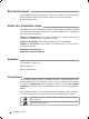
Contents Chapter 1 Introduction ——————————— 01 1.1 Product Overview ...................................................................01 1.2 Features ......................................................................................01 1.3 Appearance ...............................................................................01 Chapter 2 Installation ———————————— 04 2.1 Package Contents ...................................................................04 2.2 Safety Precautions ........
Redundant Power Supply CCCCCCCCCC Introduction 1111 Product Overview The TP-LINK Redundant Power Supply (RPS) RPS150 is designed to maximize availability for the business network. RPS150 is used as a redundant power supply for TP-LINK RPS capable L2 and L3 Managed switches. When worked with these switches, RPS150 provides a quick failover feature to ensure that the connected switches can work uninterruptedly in the event of an internal power supply failure.
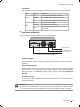
Redundant Power Supply Indicators You can monitor the running status of RPS150 through the Power and FAN LEDs. LED Power FAN ■■ Status Indication On The system power supply is normal Flashing The system power supply is abnormal Off The system power supply is off or abnormal On The fan works normally Flashing The fan works abnormally Off The power supply is off or the fan works abnormally Rear Panel of RPS150 The rear panel of RPS150 is shown as the following figure.
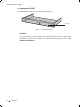
Redundant Power Supply ■■ Apearance of RPS2 The appearance of RPS2 is shown as the following figure. RPS Slot FFFFFFFFFFF Appearance of RPS2 RPS Slot To install RPS150 into RPS2, please insert RPS150 into the RPS Slot. Each RPS2 is designed to hold up to 2 RPS150. For detail instructions, please refer to 2.4 Product Installation.
Redundant Power Supply CCCCCCCCCC Installation 2222 Package Contents Make sure that the package contains the following items. If any of the listed items is damaged or missing, please contact your distributor.
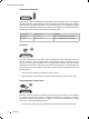
Redundant Power Supply Temperature/Humidity 40℃ 0℃ Please keep a proper temperature and humidity in the equipment room. Too high/low humidity may lead to bad insulation, electricity leakage, mechanical property changes and corrosions. Too high temperature may accelerate aging of the insulation materials and can thus significantly shorten the service life of the device. For normal temperature and humidity of the device, please check the following table.
Redundant Power Supply ■■ ■■ Keep the device far from high-frequency, strong-current devices, such as radio transmitting station. Use electromagnetic shielding when necessary. Lightening Protection Extremely high voltage currents can be produced instantly when lightning occurs and the air in the electric discharge path can be instantly heated up to 20,000℃. As this instant current is strong enough to damage electronic devices, more effective lightning protection measures should be taken.
Redundant Power Supply 2222 Installation Tools ■■ Phillips Screwdriver ■■ ESD-preventive wrist wrap 2222 Product Installation The RPS150 can be installed either in a standard 19-inch rack via RPS2 or directly on a tabletop. ■■ Desktop Installation To install the device on the desktop, please follow the steps: Caution: Please set 5~10cm gaps around the device for heat dissipation and air circulation. Please avoid any heavy thing placed on the device.
Redundant Power Supply 333Secure the RPS2 to each side of the fixed guide slot with screws. Verify the stability and horizontality of RPS2 in the rack. Rack RPS2 RPS Slot FFFFFFFFFFF Install the RPS2 to a standard rack 444Insert the RPS150 in to the RPS2 and fix it with screws, as illustrated in the figure below: FFFFFFFFFFF Insert RPS150 into RPS2 Note: Do not attach the supplied rubber feet on the bottom of RPS150 if it is supposed to be inserted into RPS2 in the bracket.
Redundant Power Supply CCCCCCCCCC Connection 3333 Connect to Ground Connecting the device to ground is to quickly release the lightning over-voltage and over-current of the device, which is also a necessary measure to protect the body from electric shock. In different environments, the device may be grounded differently. The following will instruct you to connect the device to the ground in two ways, connecting to the grounding bar or connecting to the ground via the power cord.
Redundant Power Supply 3333 Connect to the Powered Device RPS INPUT The RPS150 can be used as a redundant backup power supply unit for multiple switch models. Follow the steps below to connect the RPS150 to a powered device. 111Confirm that the power supply of the RPS150 is cut off. 222Remove the protective covers covering the redundant power socket of RPS150 and the switch.
Redundant Power Supply 3333 Power On The RPS150 requires 100-240V~50/60HZ AC power input. 111Confirm that the power supply satisfies the requirement of the input voltage of RPS150; 222Plug the negative connector of the provided AC power cord into the power socket of RPS150, and the positive connector into a power outlet as the following figure shown. After RPS150 is powered on normally, the Power LED and FAN LED indicators on its front panel will light on all the time.
Redundant Power Supply Appendix A Specifications Item Content AC Power Input 100-240V~ 50/60Hz 2.5A DC Power Output 12V 12.
Redundant Power Supply Appendix B Technical Support ■■ ■■ For more help, please go to: http://www.tp-link.com/en/support/faq To download the latest Firmware, Driver, Utility and User Guide, please go to: http://www.tp-link.com/en/support/download ■■ 13 For all other technical support, please contact us by using the following details: Global Tel: +86 755 2650 4400 Fee: Depending on rate of different carriers, IDD. E-mail: support@tp-link.
Redundant Power Supply Russian Federation Tel: 8 (4991 754 5560 (Moscow NO.1 8 (8001 250 5560 (Toll-free within RF1 E-mail: support.ru@tp-link.com Service time: From 9:00 to 21:00 (Moscow time1 *Except weekends and holidays in RF Singapore Tel: +65 6284 0493 Fee: Depending on rate of different carriers. E-mail: support.sg@tp-link.com Service time: 24hrs, 7 days a week Switzerland Tel: +41 (01 848 800 998 (German Service1 Fee: 4-8 Rp/min, depending on rate of different time. E-mail: support.ch@tp-link.
Website: http://www.tp-link.com E-mail: smb@tp-link.com.cn 7106504299 REV1.0.