Business Networking Solution Installation Guide JetStream Gigabit L2 Managed Switch T2600G-18TS (TL-SG3216) T2600G-28TS (TL-SG3424) T2600G-52TS (TL-SG3452) T2600G-28MPS (TL-SG3424P)
About this Installation Guide This Installation Guide describes the hardware characteristics, installation methods and the points that should be attended to during the installation. This Installation Guide is structured as follows: Chapter 1 Introduction. This chapter describes the external components of the switch. Chapter 2 Installation. This chapter illustrates how to install the switch. Chapter 3 Lightning Protection. This chapter illustrates how to prevent lightning damage. Chapter 4 Connection.
JetStream Gigabit L2 Managed Switch Contents Chapter 1 Introduction———————————— 01 1.1 1.2 Product Overview..................................................01 Appearance.............................................................01 Chapter 2 Installation———————————— 07 2.1 Package Contents................................................07 2.3 Installation Tools....................................................09 2.2 2.4 Safety Precautions...............................................
JetStream Gigabit L2 Managed Switch Chapter 1 1.1 Introduction Product Overview T260 0 G -18TS , T260 0 G -28TS , T260 0 G -52TS and T260 0 G -28 MPS are G igabit Et hernet sw itching product s recentl y developed by TP- Link . T260 0G -18TS possesses 16 RJ45 por ts and 2 SFP slots . T260 0G -28TS/ T260 0G -28MPS possesses 24 RJ45 por ts and 4 SFP slots. T2600G-52TS characterizes with 48 RJ45 ports and 4 SFP slots.
JetStream Gigabit L2 Managed Switch The front panel of T2600G-28TS is shown as the following figure. Figure 1-2 Front Panel of T2600G-28TS T2600G-28TS LEDs Console (RJ45) Console (USB) 10/100/1000Mbps RJ45 Port SFP Port LEDs LED PWR SYS 1000Mbps Link/Act Status Indication On The switch is powered on. Flashing Power supply is abnormal. Off Flashing On/Off On Off On Flashing Off The switch is powered off or power supply is abnormal. The switch works properly.
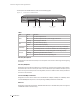
JetStream Gigabit L2 Managed Switch The front panel of The T2600G-52TS is shown as the following figure. Figure 1-3 Front Panel of T2600G-52TS Console Console(USB) Console (USB) Console (RJ45) 10/100/1000Mbps RJ45 Port LEDs SFP Port Console (USB) Port Designed to connect with the USB port of a computer for monitoring and configuring the switch. The switch has an RJ-45 console port and a micro-USB console port available. Console input is active on only one console port at a time.
JetStream Gigabit L2 Managed Switch SFP Port Designed to install the SFP module. T2600G-52TS features 4 individual SFP ports and supports 1000M SFP module connection only. The front panel of The T2600G-28MPS is shown as the following figure. Figure 1-4 Front Panel of T2600G-28MPS LEDs Console (RJ45) Console (USB) 10/100/1000Mbps RJ45 Port SFP Port T2600G-28MPS has an LED mode switch button which is for switching the LED status indication.
JetStream Gigabit L2 Managed Switch LEDs LED PWR SYS Status Indication Off The switch is powered off or power supply is abnormal. On The switch is powered on. Flashing Power supply is abnormal. Flashing The switch works properly. On/Off The switch works improperly. The remaining PoE power≤7W. On PoE Max The remaining PoE power keeps≤7W after this LED is on for 2 minutes. Flashing The remaining PoE power>7W. Off FAN Speed or PoE (Port 1-24) Green All the fans work properly.
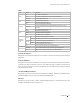
JetStream Gigabit L2 Managed Switch Port Feature Model 10/100/1000Mbps RJ45 Port SFP Port Console Port T2600G-28TS 24 4 2 T2600G-18TS T2600G-52TS T2600G-28MPS 16 48 24 2 2 4 2 4 2 Rear Panel ■■ The rear panel of the switch is shown as the following figure. Figure 1-5 Rear Panel 100-240V~50/60Hz 0.5A Kensington Security slot Grounding Terminal Power Socket Kensington Security Slot Secure the lock (not provided) into the security slot to prevent the device from being stolen.
JetStream Gigabit L2 Managed Switch Chapter 2 2.1 Installation Package Contents Make sure that the package contains the following items. If any of the listed items is damaged or missing, please contact your distributor. One Power Cord, One Console Cable and One USB Cable One Switch This Installation Guide Business Networking Solution Installation Guide Two mounting brackets and the fittings One Resouce CD 2.
JetStream Gigabit L2 Managed Switch Please keep a proper temperature and humidity in the equipment room. Too high/low humidity may lead to bad insulation, electricity leakage, mechanical property changes and corrosions. Too high temperature may accelerate aging of the insulation materials and can thus significantly shorten the service life of the device. For normal temperature and humidity of the device, please check the following table.
JetStream Gigabit L2 Managed Switch enough to damage electronic devices, more effective lightning protection measures should be taken. ■■ Ensure the rack and device are well earthed. ■■ Make sure the power socket has a good contact with the ground. ■■ Keep a reasonable cabling system and avoid induced lightning. ■■ Use the signal SPD (Surge Protective Device) when wiring outdoor. Note: For detailed lightning protection measures, please refer to Chapter 3 Lightning Protection.
JetStream Gigabit L2 Managed Switch Figure 2-1 Desktop Installation Feet Bottom of the Device Notch Rack Installation ■■ To install the device in an EIA standard-sized, 19-inch rack, follow the instructions described below: 1. Check the grounding and stability of the rack. 2. Secure the supplied rack-mounting brackets to each side of the device with supplied screws, as illustrated in the following figure. Figure 2-2 Bracket Installation Rack-mounting Bracket Screw 3.
JetStream Gigabit L2 Managed Switch Chapter 3 3.1 Lightning Protection Cabling Reasonably In the actual network environment, you may need cable outdoors and indoors, and the requirements for cabling outdoors and indoors are different. A reasonable cabling system can decrease the damage of induced lightning to devices. Note: It's not recommended using Ethernet cables outdoors. When cabling outdoors, please use a signal lightning arrester.
JetStream Gigabit L2 Managed Switch ■■ Requirements for Cabling Indoors When cabling indoors, keep a certain distance away from the devices that may cause highfrequency interferences, such as down-conductor cable, powerline, power transformer and electromotor. ■■ ■■ The main cable should be paved in the metal raceway of the access shaft. When cabling, keep the loop area formed by the cable itself as small as possible.
JetStream Gigabit L2 Managed Switch Device Min Distance (m) Transformer room 2.00 Switch case Elevator tower Air-conditioner room 3.2 1.00 2.00 2.00 Connect to Ground Connecting the device to ground is to quickly release the lightning over-voltage and over-current of the device, which is also a necessary measure to protect the body from electric shock. In different environments, the device may be grounded differently.
JetStream Gigabit L2 Managed Switch ■■ Connecting to the Ground via the Grounding Terminal Use the grounding bar If the device is installed in the Equipment Room, where a grounding bar is available, you are recommended to connect the device to the grounding bar as shown in the following figure. Figure 3-1 Connecting to the Grounding Bar Switch (Rear Panel) Ground Cable Grounding Terminal Grounding Bar Note: The grounding bar and the ground cable are not provided with our product.
JetStream Gigabit L2 Managed Switch When equipotential bonding, please note that the cable should be copper wrapped Kelly with its area being 6mm 2 at least. The shorter cable the better, and use a grounding bar to establish an equipotential bonding point. Note: The equipotential bonding cable and ground cable are not provided with our product. If needed, please self purchase it. Use Lightning Arrester Power lightning arrester and signal lightning arrester are used for lighting protection.
JetStream Gigabit L2 Managed Switch Chapter 4 4.1 Connection Ethernet Port Connect an Ethernet port of the switch to the computer by RJ45 cable as the following figure shows. Figure 4-1 Connecting the RJ45 Port RJ45 Port 4.2 RJ45 Cable SFP Port Figure 4-2 demonstrates the connection of SFP port to an SFP module. Figure 4-2 Inserting the SFP Module SFP Slot SFP Module 4.
JetStream Gigabit L2 Managed Switch Figure 4-3 Connecting the Console (RJ-45) Port Console(RJ45) Connect the Console (USB) port of the device with your computer by the USB cable as the following figure shows. Figure 4-4 Connecting the Console (USB) Port Console(USB) T2600G -28TS You can also manage the device through the console port, for details please refer to the CLI Reference Guide on the resource CD. Note: ■■ ■■ ■■ 4.4 Console (RJ-45) port and Console (USB) port cannot be used cocurrently.
JetStream Gigabit L2 Managed Switch 4.5 ■■ The power socket, device and rack are well grounded. ■■ The device is correctly connected to other network devices. Power On Plug in the negative connector of the provided power cord into the power socket of the device, and the positive connector into a power outlet as the following figure shows. Figure 4-5 Connecting to Power Supply 100-24 0V~50/6 0Hz 0.5A Note: The figure is to illustrate the application and principle.
JetStream Gigabit L2 Managed Switch Chapter 5 5.1 Configuration Configure the Switch via GUI 1. To access the GUI of the switch, open a web browser and type the default management address http://192.168.0.1 in the address field of the browser, then press the Enter key. Figure 5-1 Web Browser Note: To log on to the GUI of the switch, the IP address of your PC should be set in the same subnet addresses of the switch. The IP address is 192.168.0.x ("x" is any number from 2 to 254), Subnet Mask is 255.
JetStream Gigabit L2 Managed Switch Figure 5-3 Main Page of the Switch 5.2 Configure the Switch Using CLI You can log on to the switch and access the CLI by the following two methods: ■■ Log on to the switch by the Console (USB) port or Console (RJ-45) port on the switch. ■■ Log on to the switch remotely by a Telnet or SSH connection through an Ethernet port. ■■ Logon by a Console Port The switch has two console ports: an RJ-45 console port and a Micro-USB console port.
JetStream Gigabit L2 Managed Switch 4. Configure the terminal emulation program or the terminal. You can use the default settings as follows: ■■ Baud rate: 38400 bps ■■ Data bits: 8 ■■ Parity: none ■■ Stop bits: 1 ■■ Flow control: none 5. The DOS prompt ”T2600G-28TS>” will appear after pressing the Enter button as Figure 5-4 shows. It indicates that you can use the CLI now.
JetStream Gigabit L2 Managed Switch 4. Type telnet 192.168.0.1 in the command prompt shown as Figure 5-6, and press the Enter button. Figure 5-6 Connecting the Switch 5. Type the default user name and password (both of them are admin), then press the Enter button so as to enter User EXEC Mode. Figure 5-7 Enter into the User EXEC Mode For detailed CLI configuration instructions, please refer to the CLI Reference Guide on the resource CD.
JetStream Gigabit L2 Managed Switch Appendix A Troubleshooting Q1. What could I do if I forgot the username and password of the switch? 1. Connect the console port of the PC to the console port of the switch and open a terminal emulation 2. Power off and restart the switch. Perform the action indicated by the terminal emulation program to reach the bootUtil menu. The action differs from product to product. Possible actions are listed below: program. • 3. • Press any key to stop autoboot.
JetStream Gigabit L2 Managed Switch Q3. What should I do if I cannot access the web management page? Please try the following: 1. Check every port LED on the switch and make sure the Ethernet cable is connected properly. 3. Power off the switch and, after a while, power it on again. 2. 4. 5. Try another port on the switch and make sure the Ethernet cable is suitable and works normally. Make sure the IP address of your PC is set within the subnet of the switch.
JetStream Gigabit L2 Managed Switch Appendix B Hardware Specifications Item Standards Content IEEE 802.3, IEEE 802.3i, IEEE 802.3u, IEEE 802.3ab, IEEE 802.3ad, IEEE 802.3z, IEEE 802.3x, IEEE 802.1p, IEEE 802.1q, IEEE 802.1x, IEEE 802.1d, IEEE 802.1s, IEEE 802.1w IEEE 802.3af/at (For T2600G-28MPS only) 10Base-T: UTP/STP of Cat. 3 or above Transmission Medium 100Base-TX: UTP/STP of Cat. 5 or above 1000Base-T: 4-pair UTP (≤100m) of Cat. 5e, and Cat.
FCC STATEMENT This equipment has been tested and found to comply with the limits for a Class A digital device, pursuant to part 15 of the FCC Rules. These limits are designed to provide reasonable protection against harmful interference when the equipment is operated in a commercial environment. This equipment generates, uses, and can radiate radio frequency energy and, if not installed and used in accordance with the instruction manual, may cause harmful interference to radio communications.
BSMI Notice 安全諮詢及注意事項 1) 請使用原裝電源供應器或只能按照本產品注明的電源類型使用本產品。 2) 清潔本產品之前請先拔掉電源線。請勿使用液體、噴霧清潔劑或濕布進行清潔。 3) 注意防潮,請勿將水或其他液體潑灑到本產品上。 4) 插槽與開口供通風使用,以確保本產品的操作可靠並防止過熱,請勿堵塞或覆蓋開口。 5) 請勿將本產品置放於靠近熱源的地方。除非有正常的通風,否則不可放在密閉位置中。 6) 請不要私自打開機殼,不要嘗試自行維修本產品,請由授權的專業人士進行此項工作。 7) 此為甲類資訊技術設備,于居住環境中使用時,可能會造成射頻擾動,在此種情況下,使用者會被要求採取某些適當的對策。 Industry Canada Statement CAN ICES-3 (A)/NMB-3(A) Explanation of the symbols on the product label Symbol Explanation AC voltage Indoor use only RECYCLING This product bears the selective sorting symbo
For technical support and other information, please visit http://www.tp-link.com/support, or simply scan the QR code. The products of TP-Link partly contain software code developed by third parties, including software code subject to the GNU General Public License (“GPL”). As applicable, the terms of the GPL and any information on obtaining access to the respective GPL Code used in TP-Link products are available to you in GPL-Code-Centre under (http://www.tp-link.com/en/support/gpl/).