
Installation Instructions

JetStream Gigabit L2 Managed Switch
18
Connection
■
The power socket, device and rack are well grounded.
■
The device is correctly connected to other network devices.
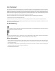
4.5 Power On
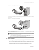
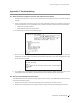
Plug in the negative connector of the provided power cord into the power socket of the device, and
the positive connector into a power outlet as the following figure shows.
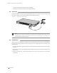
Figure 4-5 Connecting to Power Supply
100-240V~50/60Hz 0.5A
Note:
The figure is to illustrate the application and principle. The power plug you get from the
package and the socket in your situation will comply with the regulation in your country, so
they may dier from the gure above.
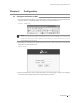
4.6 Initialization
After the device is powered on, it begins the Power-On Self-Test. A series of tests run automatically
to ensure the device functions properly. During this time, its LED indicators will respond in the
following order:
1. The PWR LED indicator lights on all the time. The SYS LED and the LED indicators of all the ports
keep off.
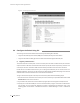
2. After about one minute, the SYS LED and LED indicators of all the ports will flash momentarily and
then turn off.
3. Several seconds later, the SYS LED indicator will flash, which represents a successful
initialization.