User Guide TL-SF1016 TL-SF1016DS TL-SF1024 TL-SF1024D TL-SF1048 16/24/48-port 10/100Mbps Fast Ethernet Switch Rev: 2.0.
COPYRIGHT & TRADEMARKS Specifications are subject to change without notice. is a registered trademark of TP-LINK TECHNOLOGIES CO., LTD. Other brands and product names are trademarks or registered trademarks of their respective holders. No part of the specifications may be reproduced in any form or by any means or used to make any derivative such as translation, transformation, or adaptation without permission from TP-LINK TECHNOLOGIES CO., LTD. Copyright © 2011 TP-LINK TECHNOLOGIES CO., LTD.
FCC STATEMENT This equipment has been tested and found to comply with the limits for a Class A digital device, pursuant to part 15 of the FCC Rules. These limits are designed to provide reasonable protection against harmful interference when the equipment is operated in a commercial environment. This equipment generates, uses, and can radiate radio frequency energy and, if not installed and used in accordance with the instruction manual, may cause harmful interference to radio communications.
CONTENTS Package Contents ................................................................................................ 1 Chapter 1 Product Introduction....................................................................... 2 1.1 Product Overview .............................................................................................2 1.2 Features ...........................................................................................................
Package Contents The following contents should be found in your box: ¾ One TL-SF1016/TL-SF1016DS/TL-SF1024/TL-SF1024D/TL-SF1048 Switch ¾ One power cord ¾ This User Guide ¾ Mounting screws and two “L” planks Note: Make sure that the package contains the above items. If any of the listed items are damaged or missing, please contact with your distributor. TL-SF1016DS and TLSF1024D do not include mounting screws and two “L” planks.
Chapter 1 Product Introduction This chapter describes the features of the model of TL-SF1016/TL-SF1016DS/TLSF1024/TL-SF1024D/TL-SF1048 16/24/48-port 10/100Mbps Fast Ethernet Switch. TL-SF1016, TL-SF1024 and TL-SF1048 just differ in the size, the number of LED indicators and ports, and all figures in this guide are of TL-SF1016. 1.1 Product Overview TL-SF1016/TL-SF1016DS/TL-SF1024/TL-SF1024D/TL-SF1048 16/24/48-port Switch provides 16/24/48 10/100Mbps Auto-Negotiation RJ45 ports.
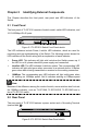
Chapter 2 Identifying External Components This Chapter describes the front panel, rear panel and LED indicators of the Switch. 2.1 Front Panel The front panel of TL-SF1016 consists of switch model, switch LED indicators, and 16 10/100Mbps RJ-45 ports. Figure 2-1 TL-SF1016 Switch Front Panel sketch The LED indicators include Power, Link/Act LED indicators, which are used for monitoring and pre-troubleshooting of the Switch.
¾ Grounding Terminal: TL-SF1016 already comes with Lightning Protection Mechanism. You can also ground the Switch through the PE (Protecting Earth) cable of AC cord or with Ground Cable. For detail information, please refer to section 3.3 Connect to Ground. ¾ AC Power Socket: Connect the female connector of the power cord here, and the male connector to the AC power outlet. Please make sure the voltage of the power supply meets the requirement of the input voltage.
Chapter 3 Installation 3.1 Precautions To ensure a long-term and stable performance of the Switch, please pay attention to the following before the installation. 1) Safety Requirements • Before cleaning the Switch, cut off the power supply. Do not clean it by the waterish cloth, and never use any other liquid cleaning method. • Take waterproof measures during storage, transportation and operation of the equipment. • Use only the power cord provided with the Switch.
3.2 Installation This Switch can be either installed on the standard 19-inch mountable rack or located on the desktop. Caution: Please unplug the power cord before installing or removing the Switch. 3.2.1 Desktop Installation To install the Switch on the desktop, please follow the steps: 1) Set the Switch on a flat surface strong enough to support the entire weight of the Switch with all fittings. 2) Remove the adhesive backing papers from the rubber feet.
1) Secure the supplied rack-mounting brackets to each side of the Switch with supplied screws, as illustrated in the following figure. Figure 3-2 Attaching Brackets 2) After the brackets are attached to the Switch, use suitable screws (not provided) to secure the brackets to the rack, as illustrated in the following figure. Figure 3-3 Mounting Switch 3) Connect the Switch to network devices. 4) Supply power to the Switch with the provided power cord.
3.3 Connect to Ground Connecting the Switch to ground is to quickly release the lightning over-voltage and over-current of the Switch, which is also a necessary measure to protect the body from electric shock. In different environments, the Switch may be grounded differently. The following will instruct you to connect the Switch to the ground in two ways, connecting to the Grounding Bar or connecting to the Ground via the power cord.
Figure 3-5 * The figure is to illustrate the application and principle. The power plug you get from the package and the socket in your situation will comply with the regulation in your country, so they may differ from the figure above. Note: If you intend to connect the Switch to the ground via the PE (Protecting Earth) cable of AC power cord, please make sure the PE (Protecting Earth) cable in the electrical outlet is well grounded in advance. 3.
Appendix A: Specifications General Standards IEEE802.3 10Base-T, IEEE802.
Appendix B: Troubleshooting 1. The Power LED is not lit ¾ Make sure the AC power cord connected the Switch with power source properly. ¾ Make sure the power source is ON. 2. The Link/Act LED is not lit when a device is connected to the corresponding port ¾ Make sure that the cable connectors are firmly plugged into the Switch and the device. ¾ Make sure the connected device is turned on and working well. ¾ The cable must be less than 100 meters long (328 feet).