TL-SG1016DE/TL-SG1024DE 16/24-port Gigabit Easy Smart Switch REV1.0.
COPYRIGHT & TRADEMARKS Specifications are subject to change without notice. is a registered trademark of TP-LINK TECHNOLOGIES CO., LTD. Other brands and product names are trademarks or registered trademarks of their respective holders. No part of the specifications may be reproduced in any form or by any means or used to make any derivative such as translation, transformation, or adaptation without permission from TP-LINK TECHNOLOGIES CO., LTD. Copyright © 2013 TP-LINK TECHNOLOGIES CO., LTD.
Safety Information z z z When product has power button, the power button is one of the way to shut off the product; When there is no power button, the only way to completely shut off power is to disconnect the product or the power adapter from the power source. Don’t disassemble the product, or make repairs yourself. You run the risk of electric shock and voiding the limited warranty. If you need service, please contact us. Avoid water and wet locations.
CONTENTS Package Contents ..........................................................................................................................1 Chapter 1 About this Guide...........................................................................................................2 1.1 Intended Readers .........................................................................................................2 1.2 Conventions.................................................................................
.4 802.1Q PVID Setting ..................................................................................................27 Chapter 6 QoS............................................................................................................................29 6.1 QoS Basic...................................................................................................................30 6.2 Bandwidth Control .........................................................................................
Package Contents The following items should be found in your box: ¾ One 16/24-port Gigabit Easy Smart Switch ¾ One power cord ¾ Two mounting brackets and other fittings ¾ Installation Guide ¾ Resource CD for TL-SG1016DE/TL-SG1024DE switch, including: • This User Guide • Other Helpful Information Note: Make sure that the package contains the above items. If any of the listed items are damaged or missing, please contact your distributor.
Chapter 1 About this Guide This User Guide contains information for setup and management of TL-SG1016DE/TL-SG1024DE 16/24-port Gigabit Easy Smart Switch. Please read this guide carefully before operation. 1.1 Intended Readers This Guide is intended for network managers familiar with IT concepts and network terminologies. 1.
Chapter Introduction Chapter 3 Login to the Switch Introduces how to log on to the Web management page. Chapter 4 System This module is used to configure system properties of the switch. Here mainly introduces: z System Info: View device information and define the device description. z IP Setting: Get and modify the network parameters of the switch. z User Account: Modify the username and password for users to log on to the Web management page. z Switching: Configure the basic functions of the switch.
Chapter 2 Introduction Thanks for choosing the TL-SG1016DE/TL-SG1024DE 16/24-port Gigabit Easy Smart Switch! 2.1 Overview of the Switch The TL-SG1016DE/TL-SG1024DE 16/24-port Gigabit Easy Smart Switch is an ideal upgrade from an unmanaged switch, designed for Small and Medium Business networks that require simple network management. Network administrators can effectively monitor traffic via Port Mirroring, Loop Prevention and Cable Test features.
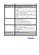
The following parts are located on the front panel of the switch: ¾ Reset: With the switch powered on, press this button for five seconds or above to reset the software setting back to factory default setting. ¾ 1000Mbps Ports: Designed to connect to the device with a bandwidth of 10Mbps, 100Mbps or 1000Mbps. Each has a corresponding 1000Mbps LED and link/Act LED. ¾ LEDs Name Status On Power 1000Mbps Link/Act Flashing Indication Power is on. Power supply is abnormal.
Chapter 3 Login to the Switch 3.1 Login 1) To access the configuration utility, open a web-browser and type the default address http://192.168.0.1 in the address field of the browser, then press the Enter key. Figure 3-1 Web-browser Tips: To log in to the switch, the IP address of your PC should be set in the same subnet addresses of the switch. The IP address is 192.168.0.x ("x" is any number from 2 to 254), Subnet Mask is 255.255.255.0.
Figure 3-3 Main Setup-Menu Note: Clicking Apply can only make the new configurations effective before the switch is rebooted. If you want to keep the configurations effective even the switch is rebooted, please click Save Config. You are suggested to click Save Config before cutting off the power or rebooting the switch to avoid losing the new configurations.
Chapter 4 System The System module is mainly for basic settings of the switch, including six submenus: System Info, IP Setting, User Account, Switching, Monitoring and System Tools. 4.1 System Info On this page you can view the system information and define the device description. Choose the menu System→System Info to load the following page. Figure 4-1 System Info The following entries are displayed on this screen: ¾ System Info Device Description: Displays the device model number.
Figure 4-2 IP Address Setting The following entries are displayed on this screen: ¾ IP Address Setting DHCP Setting: Allows you to enable or disable the switch to serve as DHCP client. If DHCP client is enabled, the switch will obtain the IP address, subnet Mask and default gateway from the DHCP Server automatically; otherwise, these three items should be configured manually. By default, it is disabled. IP Address: Specify the system IP address of the switch. The default system IP address is 192.168.0.
Figure 4-3 User Account Setting You are kindly suggested to retype the new password in "Confirm Password" box instead of copying in order to avoid mistakes. Note: 1. The length of user name and password should not be more than 16 characters using digits, English letters and underlines only. 2. The default username/password is admin/admin. 4.4 Switching Switching module is used to configure the basic functions of the switch, including three submenus: Port Setting, IGMP Snooping and Port Trunk. 4.4.
Figure 4-4 Port Setting The following entries are displayed on this screen: ¾ Port Setting Port: Select the desired port for configuration. It is multi-optional. Status: Allows you to enable of disable the port. “Enable" Indicates that the port is operational and "Disable" indicates the port is non-operational. If a port is unused for a long time, its status can be set to “Disable” to cut down the energy cost. Speed/Duplex: Select the Speed and Duplex mode for the port.
Note: The switch cannot be managed through the disabled port. Please enable the port which is used to manage the switch. 4.4.2 IGMP Snooping Internet Group Management Protocol (IGMP) snooping is a multicast control mechanism, which can be used on the switch for dynamic registration of the multicast group. IGMP Snooping allows the switch to recognize the IGMP messages transmitted between network stations or devices and an IGMP host.
z For the newly joined member ports in a trunk group, their default setting of Port setting (Speed and Duplex, Flow Control), QoS will be configured the same as that of the first member port in the trunk group. z The trunk member ports cannot be set as mirroring port. z Before setting the trunk, its member ports should be divided to the same VLAN, and have the same PVID and drop the untagged packet rule. Change of the trunk setting will not affect the VLAN setting.
Port: Select the port as the trunk group member. It is multi-optional. Clearing all the ports of the trunk group will delete this trunk group. Tips: Calculate the bandwidth for a trunk group: If a trunk consists of the four ports whose Speed/Duplex mode is 1000Mbps/Full Duplex, the whole bandwidth of the trunk group is up to 8000Mbps (2000Mbps * 4) because the bandwidth of each member port is 2000Mbps counting the up-linked speed of 1000Mbps and the down-linked speed of 1000Mbps. 4.
Link Status: Displays whether the port is link up or link down. TxGoodPkt: Displays the number of good packets transmitted on the port. The error packets are not counted in. TxBadPkt: Displays the number of error packets transmitted on the port. RxGoodPkt: Displays the number of good packets received on the port. The error packets are not counted in. RxBadPkt: Displays the number of error packets received on the port. 4.5.
Figure 4-8 Port Mirror The following entries are displayed on this screen: ¾ ¾ Port Mirror Port Mirror: Allows you to enable or disable the port mirror feature of the specified port. Mirroring Port: Select a port from the pull-down list as the mirroring port. Mirrored Port Mirrored Port: Select a port from the pull-down list as the mirrored port to monitor the traffic. Trunk member cannot be defined here. It is multi-optional.
Ingress: Select whether to monitor the ingress traffic. When the ingress is enabled, the ingress traffic received by the mirrored port will be copied to the mirroring port. Egress: Select whether to monitor the egress traffic. When the egress is enabled, the outgoing packets sent by the mirrored port will be copied to the mirroring port. Note: 1. The trunk member cannot be selected as the mirroring port. 2. A port cannot be set as the mirrored port and the mirroring port simultaneously. 3.
Test Result: Displays the connection status of the cable connected to the port. The test results of the cable include “No Cable”, “Open”, “Short”, ”Open Short”, “Normal”, “Cro Cable” and “others”. Cable Fault Distance(m): Displays the error length (in meters) of the cable. Note: The test result is just for your reference. 4.5.4 Loop Prevention With loop prevention feature enabled, the switch can detect loops using loop detection packets.
Figure 4-11 Backup and Restore The following entries are displayed on this screen: ¾ Config Backup Backup Config: ¾ Click the Backup Config button to save the current configuration as a file to your computer. You are suggested to take this measure before upgrading. Config Restore Restore Config: Click the Restore Config button to restore the backup configuration file. It will take effect after the switch automatically reboots. Note: 1. It will take a few minutes to backup the configuration.
Figure 4-12 System Reboot Note: To avoid damage, please don't turn off the device while rebooting. 4.6.3 System Reset On this page you can reset the switch to the default. All the settings will be cleared after the switch is reset. Choose the menu System→System Tools→System Reset to load the following page. Figure 4-13 System Reset Note: After the system is reset, the switch will be reset to the default and all the settings will be cleared. 4.6.
Figure 4-14 Firmware Upgrade Note: 1. Don’t interrupt the upgrade. 2. You are suggested to backup the configuration before upgrading. 3. Please select the proper software version matching with your hardware to upgrade. 4. To avoid damage, please don't turn off the device while upgrading. 5. After upgrading, the device will reboot automatically.
Chapter 5 VLAN The traditional Ethernet is a data network communication technology based on CSMA/CD (Carrier Sense Multiple Access/Collision Detect) via shared communication medium. Through the traditional Ethernet, the overfull hosts in LAN will result in serious collision, flooding broadcasts, poor performance or even breakdown of the Internet.
each of the other ports. Each VLAN contains two ports, the uplink port and one of the other ports in the switch, so the uplink port can communicate with any other port but other ports cannot communicate with each other. 2. Port Based VLAN VLANs are divided based on ports. By default, the Port Based VLAN is enabled. 3. 802.1Q VLAN The IEEE 802.1Q protocol defines a new format of the frame; it adds a Tag header in the original Ethernet frame, as follows: Figure 5-2 IEEE 802.
Figure 5-3 MTU VLAN Configuration Note: 1. The uplink port will form several VLANs with each of the other ports. Each VLAN contains two ports, the uplink port and one of the other ports in the switch, thus the uplink port can communicate with any other port but other ports cannot communicate with each other. 2. For the first time the MTU VLAN mode is enabled, the switch will set port 1 as the uplink port by default. 5.
The following entries are displayed on this screen: ¾ Port Based VLAN Configuration Port Based VLAN Configuration: Enable or disable Port Based VLAN mode. VLAN ID: Enter the ID number of VLAN. It ranges from 2 to 32. Port: Displays the port number. Member: Click the check box to select the port of the VLAN. It is multi-optional. If this field is checked, it indicates the port belongs to the current VLAN. Note: A VLAN cannot be the subset or superset of the other VLANs. 5.3 802.
Figure 5-5 802.1Q VLAN Configuration To ensure the normal communication of the factory switch, the default VLAN of all ports is set to be VLAN1. VLAN 1 cannot be modified or deleted. The following entries are displayed on this screen: ¾ 802.1Q VLAN Configuration 802.1Q VLAN Configuration: Enable or disable 802.1Q VLAN mode. VLAN ID: Enter the ID number of VLAN. It ranges from 2 to 4094. VLAN Name: Give a name to the VLAN for identification. Port: Displays the port number.
Tagged: Click the check box to configure the egress rule of the traffic on this port as tagged. The switch adds the tag header before sending the packet. Not Member: Click the check box to exclude the port from the current VLAN. 5.4 802.1Q PVID Setting PVID (Port Vlan ID) is the default VID of the port. When the switch receives an un-VLAN-tagged packet, it will add a VLAN tag to the packet according to the PVID of its received port and forward the packets.
¾ 802.1Q VLAN Port Setting Select: Select the desired port for configuration. It is multi-optional. Port: Displays the port number. PVID: Enter a PVID number for the port. When adding the tag header to the received untagged packet, the switch will automatically uses this PVID value as the VLAN ID of the added tag. Note: 802.1Q VLAN should be enabled before setting PVID.
Chapter 6 QoS QoS (Quality of Service) functions to provide different quality of service for various network applications and requirements and optimize the bandwidth resource distribution so as to provide a network service experience of a better quality. ¾ QoS This switch classifies the ingress packets, maps the packets to four different priority queues and then forwards the packets according to Strict-Priority scheduling algorithms to implement QoS function.
to four different priority queues. After that, the switch will preferentially send packets in the queue with higher priority, and only when the queue with higher priority is empty, packets in the queue with lower priority are sent. 2. 802.1P Based Figure 6-2 802.1Q frame As shown in the figure above, each 802.1Q Tag has a Pri field, comprising 3 bits. The 3-bit priority field is 802.1p priority in the range of 0 to 7. The 802.
Figure 6-4 QoS Basic The following entries are displayed on this screen: ¾ Global Config QoS Mode: Select the desired QoS mode. • Port Based: The switch classifies the ingress packets and maps the packets to different priority queues based on which port the packets come from. • 802.
and maps the packets to different priority queues based on the 802.1p priority field in the 802.1Q tag. ¾ Port-based Priority Setting Port: Select the desired port to configure its priority queue. It is multi-optional. Priority Queue: Specify the priority queue the packets from the port are mapped to. The priorities are labeled as 1~4 and among them the bigger the value, the higher the priority. 6.
The following entries are displayed on this screen: ¾ Bandwidth Control Setting Port: Select the desired port for bandwidth control configuration. It is multi-optional. Status: Allows you to enable or disable the bandwidth control function.. Rate(Kbit/sec): Select the rate for receiving/sending packets on the port. The packet traffic exceeding the rate will be discarded. It ranges from 0 to 100000, and must be integral multiple of 64.
Figure 6-6 Storm Control Setting The following entries are displayed on this screen: ¾ Storm Control Setting Port: Select the desired port for storm control configuration. It is multi-optional. Status: Allows you to enable or disable the storm control function. Total Rate: Select the rate for receiving packets on the port. The packet traffic exceeding the rate will be discarded. It ranges from 0 to 100000, and must be integral multiple of 64.
Included Type: Storm Select to filter broadcast/multicast/UL frame in the network, if the transmission rate of the chosen packets exceeds the set rate, the packets will be automatically discarded to avoid network broadcast storm. It is multi-optional. • UL-Frame: If UL-Frame packets traffic exceeds the rate on the port, they will be discarded. • Multicast: If multicast packets traffic exceeds the rate on the port, they will be discarded.
Appendix A: Specifications IEEE802.3 10Base-T Ethernet IEEE802.3u 100Base-TX Standards IEEE802.3ab 1000Base-T Gigabit Ethernet IEEE802.3x Flow Control IEEE802.1p QoS IEEE802.1q VLAN Ethernet: 10Mbps HD, 20Mbps FD Transmission Rate Fast Ethernet: 100Mbps HD, 200Mbps FD Gigabit Ethernet: 2000Mbps FD 10Base-T: UTP/STP of Cat. 3 or above Transmission Medium 100Base-TX: UTP/STP of Cat. 5 or above 1000Base-T: 4-pair UTP (≤100m) of Cat. 5, Cat. 5e, Cat.
Appendix B: Configuring the PCs In this section, we’ll introduce how to install and configure the TCP/IP correctly in Windows 2000. First make sure your Ethernet Adapter is working, refer to the adapter’s manual if necessary. 1) On the Windows taskbar, click the Start button, and then click Control Panel. 2) Click the Network and Internet Connections icon, and then click on the Network Connections tab in the appearing window.
5) The following TCP/IP Properties window will display and the IP Address tab is open on this window by default. Figure B-3 6) Select Use the following IP address. And the following items will be available. If the switch's IP address is 192.168.0.1, specify IP address as 192.168.0.x (x is from 2 to 254), and the Subnet mask as 255.255.255.0. Now: Click OK to save your settings.