Easy Smart Configuration Utility REV1.2.
CONTENTS Chapter 1 About this Guide.................................................................................1 1.1 Intended Readers ...................................................................................................... 1 1.2 Conventions............................................................................................................... 1 1.3 Overview of This Guide .............................................................................................
6.3 802.1Q VLAN .......................................................................................................... 31 6.4 802.1Q PVID Setting ............................................................................................... 32 Chapter 7 QoS ....................................................................................................34 7.1 QoS Basic................................................................................................................ 36 7.
Easy Smart Configuration Utility User Guide Chapter 1 About this Guide This User Guide contains information for setup and guidance of the Easy Smart Configuration Utility. Please read this guide carefully before operation. 1.1 Intended Readers This Guide is intended for network managers familiar with IT concepts and network terminologies. 1.2 Conventions In this Guide the following conventions are used: ¾ Menu Name→Submenu Name indicates the menu structure.
Easy Smart Configuration Utility User Guide Chapter Introduction Chapter 3 System This module is used to configure system properties of the switch. Here mainly introduces: Chapter 4 Switching Chapter 5 Monitoring z System Info: View device information and define the device description. z IP Setting: Get and modify the network parameters of the switch. z User Account: Modify the username and password for users to login the Web management page.
Easy Smart Configuration Utility User Guide Chapter Introduction Chapter 6 VLAN This module is used to configure VLANs to control broadcast in LANs. Here mainly introduces: z z z z Chapter 7 QoS This module is used to configure QoS function to provide different quality of service for various network applications and requirements. Here mainly introduces: z z z Chapter 8 Help MTU VLAN: Set the MTU VLAN mode. Port Based VLAN: Set the Port-Based VLAN mode 802.1Q VLAN: Set the 802.1Q Tag VLAN mode. 802.
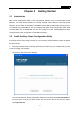
Easy Smart Configuration Utility User Guide Chapter 2 2.1 Getting Started Introduction Easy Smart Configuration Utility is the management software for the TP-LINK Easy Smart Switches. The utility allows operators to centrally manage entire networks of the Easy Smart Switches, which include TL-SG105E/TL-SG108E/TL-SG1016DE/TL-SG1024DE.
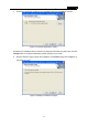
Easy Smart Configuration Utility User Guide If the home screen does not display, browse the files on the CD and double-click AutoRun.exe. You can also directly read the User Guide and double-click the icon in the Utility folder to install the utility with the same steps from the following step 2 to step 3. AutoRun is not provided on the resource CD of TL-SG1016DE/TL-SG1024DE. Please double-click the installation icon to install the utility. 2.
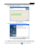
Easy Smart Configuration Utility User Guide c. Choose the destination location for the installation files and click Next to continue. Figure 2-3 Choose Destination Location By default, the installation files are saved in the Program Files folder of system disk. Click the Change button to modify the destination location properly to your need. d. Now the wizard is ready to begin the installation. Click Install to begin the installation on the following screen.
Easy Smart Configuration Utility User Guide e. The InstallShield Wizard is installing Easy Smart Configuration Utility shown as the following screen. Please wait for a while. Figure 2-5 Setup Status f. Click Finish to complete the installation on the following screen. Figure 2-6 InstallShield Wizard Complete 3.
Easy Smart Configuration Utility User Guide 2.3 Switch Discovery When the utility is launched, it immediately searches the network for TP-LINK Easy Smart Switches. The discovered switches are listed as below. Figure 2-7 Main Page Click Help in the left bottom to access the TP-LINK support website for more help. Note: The maximum number of the discovered switches is 30. 2.4 Switch Settings You can select a switch and click to configure or display its status.
Easy Smart Configuration Utility User Guide The setting figure will be shown as below: Figure 2-9 Switch Setting You can configure the switch’s Device Description, DHCP Setting, IP Address, Subnet Mask and Default Gateway on this page. The login User Name and Password are required to complete the configuration. By default, they are both admin. When the switch IP Address is not in the same subnet with host IP Address, it can be discovered by the utility, but you cannot login the utility management page.
Easy Smart Configuration Utility User Guide 2.6 Utility Features Overview You can select a switch and click or double click its corresponding entry to log on to the switch for further configuration. Please ensure that host IP address and switch IP address must be in the same subnet. Figure 2-10 Discovered Switch Enter the User Name and Password to login the configuration interface. They are both admin by default. You can select Remember Me to remember the User Name and Password.
Easy Smart Configuration Utility User Guide The configuration figure is shown as blow: Figure 2-12 Switch Configuration Device description field shows the device model number of the switch that you are managing. Click the icon to save the current configurations. Click the icon to return to the discovering page. Note: The switch you log on to should be in the same subnet with your computer.
Easy Smart Configuration Utility User Guide 2.7 Uninstall the Utility If you want to remove the Easy Smart Configuration Utility, please take the following steps: 1. On the Windows taskbar, click the Start button, point to All ProgramsÆTP-LINK Æ Easy Smart Configuration Utility, and then click Uninstall Easy Smart Configuration Utility, shown as the following figure. Figure 2-13 Preparing Setup 2. Then the following screen will appear. If you want to stop the remove process, click Cancel.
Easy Smart Configuration Utility User Guide 3. On the continued screen, click Yes to remove the utility from your PC. Figure 2-15 Uninstall the Utility 4. Click Finish to complete.
Easy Smart Configuration Utility User Guide Chapter 3 System The System module is mainly for system configuration of the switch, including seven submenus: System Info, IP Setting, User Account, Backup and Restore, System Reboot, System Reset and Firmware Upgrade. 3.1 System Info On this page you can view the system information and define the device description. Choose the menu System→System Info to load the following page.
Easy Smart Configuration Utility User Guide 3.2 IP Setting Each device in the network possesses a unique IP address. You can login the IP Setting page to operate the switch using this IP address. The switch supports the DHCP mode to obtain an IP address from the DHCP server. On this page you can get and modify the network parameters of the switch. Choose the menu System→IP Setting to load the following page.
Easy Smart Configuration Utility User Guide Figure 3-3 System User Setting The following entries are displayed on this screen: ¾ System User Setting User Name: Create a name for administrator’s login. Old Password: Type in the old password. Password: Type in a new password for administrator’s login. Confirm Password: Retype the new password. Note: 1. The length of user name and password should not be more than 16 characters using digits, letters and underlines only. 2.
Easy Smart Configuration Utility User Guide The following entries are displayed on this screen: ¾ System Config Backup Backup Config: Click the Backup Config button to save the current configuration as a file to your computer. You are suggested to take this measure before upgrading. ¾ System Config Restore Restore Config: Click the Choose File button to select the backup configuration file, and then click the Restore Config button. It will take effect after the switch automatically reboots. Note: 1.
Easy Smart Configuration Utility User Guide Choose the menu System→System Reset to load the following page. Figure 3-6 System Reset Note: After the system is reset, the switch will be reset to the default and all the settings will be cleared. 3.7 Firmware Upgrade The switch system can be upgraded via this management page. To upgrade the system is to get more functions and better performance. Go to http://www.tp-link.com to download the updated firmware.
Easy Smart Configuration Utility User Guide Chapter 4 Switching Switching module is used to configure the basic functions of the switch, including three submenus: Port Setting, IGMP Snooping and Port Trunk. 4.1 Port Setting On this page, you can configure the basic parameters for the ports. When the port is disabled, the packets on the port will be discarded. Disabling the port which is vacant for a long time can reduce the power consumption effectively. And you can enable the port when it is in need.
Easy Smart Configuration Utility User Guide Speed and Duplex: Config: Select the Speed and Duplex mode for the port. The device connected to the switch should be in the same Speed and Duplex mode with the switch. When “Auto” is selected, the Speed and Duplex mode will be determined by auto-negotiation. Actual: Displays the actual working state of the port. Flow Control: Config: Select On/Off to Enable/Disable the Flow Control feature.
Easy Smart Configuration Utility User Guide Figure 4-2 IGMP Snooping The following entries are displayed on this screen: ¾ IGMP Snooping IGMP Snooping: ¾ 4.3 Enable or disable IGMP snooping function globally on the switch. Multicast IP Table IP Address: Displays the multicast IP address. VLAN ID: Displays the VLAN ID of the multicast group. If the packet does not carry VLAN ID, then here displays the PVID of the port.
Easy Smart Configuration Utility User Guide On this page, you can configure and view the information of the trunk group of the switch. Choose the menu Switching→Port Trunk to load the following page. Figure 4-3 Trunk Config Here you can configure and view the port parameters. ¾ ¾ Trunk Config Trunk ID: Select an identified number for the trunk group from the drop-down list. Port: Select the port as the trunk group member. It is multi-optional.
Easy Smart Configuration Utility User Guide Chapter 5 Monitoring Monitoring module monitors the traffic information of the switch, and provides the convenient method to locate and solve the network problem, includes four submenus: Port Statistics, Port Mirror, Cable Test and Loop Prevention. 5.1 Port Statistics On this page you can view the statistic information of each port, which facilitates you to monitor the traffic and locate faults promptly.
Easy Smart Configuration Utility User Guide 5.2 Port Mirror Port mirror function is to monitor and mirror network traffic by forwarding copies of incoming and outgoing packets from one/multiple ports (mirrored port) to a specific port (mirroring port). Usually, the mirroring port is connected to a data diagnosis device, which is used to analyze the mirrored packets for monitoring and troubleshooting the network. Choose the menu Monitoring→Port Mirror to load the following page.
Easy Smart Configuration Utility User Guide 5.3 Cable Test This switch provides cable test to diagnose the connection status of the cable connected to the switch and the distance to the problem location, which facilitates you to locate and diagnose the trouble spot of the network. Choose the menu Monitoring→Cable Test to load the following page. Figure 5-3 Cable Test The following entries are displayed on this screen: ¾ Cable Test Port: Displays the port number of the switch.
Easy Smart Configuration Utility User Guide 5.4 Loop Prevention With loop prevention feature enabled, the switch can detect loops using loop detection packets. When a loop is detected, the switch will block the corresponding port automatically. Choose the menu Monitoring→Loop Prevention to load the following page.
Easy Smart Configuration Utility User Guide Chapter 6 VLAN The traditional Ethernet is a data network communication technology based on CSMA/CD (Carrier Sense Multiple Access/Collision Detect) via shared communication medium. Through the traditional Ethernet, the overfull hosts in LAN will result in serious collision, flooding broadcasts, poor performance or even breakdown of the Internet.
Easy Smart Configuration Utility User Guide (3) Network configuration workload for the host is reduced. VLAN can be used to group specific hosts. When the physical position of a host changes within the range of the VLAN, you do not need to change its network configuration. There are 3 types of VLAN modes supported in the switch: 1. MTU VLAN MTU VLAN (Multi-Tenant Unit VLAN) defines an uplink port which will build up several VLANs with each of the other ports.
Easy Smart Configuration Utility User Guide The VLAN module is mainly for VLAN configuration, including four submenus: MTU VLAN, Port Based VLAN, 802.1Q VLAN and 802.1Q PVID Setting. 6.1 MTU VLAN On this page you can choose to enable MTU VLAN mode and configure VLANs. Choose the menu VLAN→MTU VLAN to load the following page. Figure 6-3 MTU VLAN Configuration The following entries are displayed on this screen: ¾ 6.2 MTU VLAN Setting MTU VLAN Status: Enable/Disable the MTU VLAN function globally.
Easy Smart Configuration Utility User Guide Choose the menu VLAN→Port Based VLAN to load the following page. Figure 6-4 Port Based VLAN Configuration To ensure the normal communication of the factory switch, the default VLAN of all ports is set to VLAN1. VLAN 1 cannot be deleted. The following entries are displayed on this screen: ¾ Global Config Port Based VLAN Configuration: ¾ Enable or disable Port Based VLAN mode.
Easy Smart Configuration Utility User Guide Note: A VLAN cannot be the subset or superset of other VLANs. 6.3 802.1Q VLAN On this page you can configure 802.1Q VLAN feature and view the related settings. Choose the menu VLAN→802.1Q VLAN to load the following page. Figure 6-5 802.1Q VLAN Configuration To ensure the normal communication of the factory switch, the default VLAN of all ports is set to be VLAN1. VLAN 1 cannot be modified or deleted.
Easy Smart Configuration Utility User Guide VLAN Name: Give a name to the VLAN for identification. Untagged Ports: Click the port icon to configure the egress rule of the traffic on this port as untagged. The switch drops the tag header before sending the packet. Tagged Ports: Click the port icon to configure the egress rule of the traffic on this port as tagged. The switch adds the tag header before sending the packet. 6.4 VLAN ID: Displays the ID number of VLAN.
Easy Smart Configuration Utility User Guide Figure 6-6 802.1Q VLAN PVID Setting The following entries are displayed on this screen: ¾ 802.1Q VLAN PVID Setting Select: Select the desired port for configuration. It is multi-optional. Port: Displays the port number. PVID: Enter a PVID number for the port. When adding the tag header to the received untagged packet, the switch will automatically uses this PVID value as the VLAN ID of the added tag. LAG: Displays the LAG to which the port belongs.
Easy Smart Configuration Utility User Guide Chapter 7 QoS QoS (Quality of Service) functions to provide different quality of service for various network applications and requirements and optimize the bandwidth resource distribution so as to provide a network service experience of a better quality. ¾ QoS This switch classifies the ingress packets, maps the packets to four different priority queues and then forwards the packets according to WRR scheduling algorithms to implement QoS function.
Easy Smart Configuration Utility User Guide 1. Port Based When port-base QoS mode is enabled, the user can manually map the ingress packets of the port to four different priority queues. After that, the switch will preferentially send packets in the queue with higher priority, and only when the queue with higher priority is empty, packets in the queue with lower priority are sent. 2. 802.1P Based Figure 7-2 802.1Q Frame As shown in the figure above, each 802.1Q Tag has a Pri field, comprising 3 bits.
Easy Smart Configuration Utility User Guide 7.1 QoS Basic This switch classifies the ingress packets, maps the packets to different priority queues and then forwards the packets to implement QoS function. This switch implements two priority modes based on port and on 802.1P. The port-based QoS mode supports four priority queues. The port priority queues are labeled as 1, 2, 3, and 4. On this page you can configure and view QoS mode and the port-based priority setting.
Easy Smart Configuration Utility User Guide ¾ 7.2 Port Based Priority Setting Select: Select the desired port for configuration. It is multi-optional. Port: Displays the port number. Priority Queue: Specify the priority queue the packets from the port are mapped to. The priorities are labeled as 1~4 and among them the bigger the value, the higher the priority. LAG: Displays the LAG number which the port belongs to.
Easy Smart Configuration Utility User Guide Port: Displays the port number of the switch. Ingress Rate (bps): Configure the bandwidth for receiving packets on the port. You can select a rate from the dropdown list or select "Manual" to set Ingress rate, the system will automatically select integral multiple of 64Kbps that closest to the rate you entered as the real Ingress rate. Egress Rate(bps): Configure the bandwidth for sending packets on the port.
Easy Smart Configuration Utility User Guide Choose the menu QoS→Storm Control to load the following page. Figure 7-6 Storm Control Setting The following entries are displayed on this screen: ¾ Storm Control Config Select: Select the desired port for Storm Control configuration. It is multi-optional. Port: Displays the port number of the switch. Bc Limit: Enable/Disable broadcast control feature for the port. Mc Limit: Enable/Disable multicast control feature for the port.
Easy Smart Configuration Utility User Guide Chapter 8 Help This page contains two submenus: Help and About. 8.1 Help Choose the menu Help→Help to load the following page. Figure 8-1 Help Click Online Help to access the TP-LINK support website and the online user guide for the Easy Smart Configuration Utility (the latest copy of this manual). 8.2 About To view the utility software version, choose the menu Help→About.