
Operation Manual
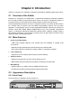


The front p
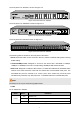
anel of TL-SG2424 is shown as Figure 2-2.
Figure 2-2 Front Panel of TL-SG2424
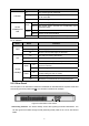
The front panel of TL-SG2424P is shown as Figure 2-3.
Figure 2-3 Front Panel of TL-SG2424P
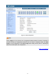
The front panel ofTL-SG2452 is shown as Figure 2-4.
Figure 2-4 Front Panel of TL-SG2452
The following parts are located on the front panel of the switch:
Reset: Press this button for five seconds or above to reset the software setting back to factory
default setting.
10/100/1000Mbps Ports: Designed to connect to the device with a bandwidth of 10Mbps,
100Mbps or 1000Mbps. Each has a corresponding 1000Mbps LED and link/Act LED.
SFP Ports: Designed to install the SFP module. TL-SG2216/TL-SG2424/TL-SG2424P switch
features some SFP transceiver slots that are shared with the associated RJ45 ports. The
associated two ports are referred to as “combo” ports, which means they cannot be used
simultaneously, otherwise only SFP ports work. TL-SG2452 features 4 individual SFP ports.
Note:
The SFP port can only be used with a gigabit module.
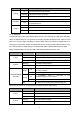
LEDs
For TL-SG2216/TL-SG2424:
Name Status Indication
On Power is on.
Flashing Power supply is abnormal.
Power
Off Power is off or power supply is abnormal.
7