Enterprise Networking Solution Installation Guide L2 Managed Switch TL-SG5428/TL-SG5412F
COPYRIGHT & TRADEMARKS Specifications are subject to change without notice. is a registered trademark of TP-LINK TECHNOLOGIES CO., LTD. Other brands and product names are trademarks of their respective holders. No part of the specifications may be reproduced in any form or by any means or used to make any derivative such as translation, transformation, or adaptation without permission from TP-LINK TECHNOLOGIES CO., LTD. Copyright © 2012 TP-LINK TECHNOLOGIES CO., LTD. All rights reserved. http://www.tp-link.
Related Document The User Guide and CLI Reference Guide of the product are provided on the resource CD. To obtain the latest product information, please visit the Official Website: http://www.tp-link.com About this Installation Guide This Installation Guide describes the hardware characteristics, installation methods and the points that should be attended to during installation. This Installation Guide is structured as follows: Chapter 1 Introduction.
Audience This Installation Guide is for: Network Engineer Network Administrator Conventions Due to the similarity in the structure of the L2 Managed Switch series, in this Installation Guide we take TL-SG5428 as an example to illustrate Chapter 2 Installation, Chapter 3 Lightning Protection and Chapter 4 Connection. This guide uses the specific formats to highlight special messages. The following table lists the notice icons that are used throughout this guide. Remind to be careful.
Contents Chapter 1 Introduction— ———————————— 01 1.1 Product Overview..........................................01 1.2 Appearance..................................................01 Chapter 2 Installation—————————————— 04 2.1 Package Contents..........................................04 2.2 Safety Precautions.........................................04 2.3 Installation Tools...........................................06 2.4 Product Installation.......................................
L2 Managed Switch CCCCCCCCCCCIntroduction 1111 Product Overview TL-SG5428 and TL-SG5412F are Gigabit Ethernet switching products recently developed by TP-LINK. TL-SG5428 possesses 24 RJ45 ports and 4 SFP slots, while TL-SG5412F characterizes with 12 SFP slots and 4 RJ45 ports. The SFP slot enables remote connection with SFP slots on other devices through SFP module and fiber. TL-SG5412F is compatible with all kinds of gigabit SFP modules.
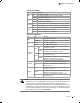
L2 Managed Switch LEDs ( for TL-SG5428 ) LED PWR SYS 1000Mbps Link/Act Status Indication On The Switch is powered on Off The Switch is powered off or power supply is abnormal Flashing Power supply is abnormal Flashing The Switch works properly On/Off The Switch works improperly On A device is linked to the corresponding port and running at 1000Mbps Off A 10/100Mbps device or no device is linked to the corresponding port On A device is linked to the corresponding port and running properl
L2 Managed Switch Port Feature Model 10/100/1000Mbps RJ45 Port SFP Port Console Port TL-SG5428 24 4 1 TL-SG5412F 4 12 1 10/100/1000Mbps RJ45 Port Designed to connect to the device with a bandwidth of 10Mbps, 100Mbps or 1000Mbps. For TL-SG5428, each 10/100/1000Mbps RJ45 port has a corresponding 1000Mbps LED and Link/Act LED. But for TL-SG5412F, each 10/100/1000Mbps RJ45 port has a corresponding 10/100/1000BASE-T LED. SFP Port Designed to install the SFP module.
L2 Managed Switch CCCCCCCCCCCInstallation 2222 Package Contents Make sure that the package contains the following items. If any of the listed items is damaged or missing, please contact your distributor. One Power Cord, One Console Cable and one Ground Cable One Switch This Installation Guide TL-SG5428 Two mounting brackets and the fittings One Resource CD TL-SG5428 2222Safety Precautions To avoid any device damage and bodily injury caused by improper use, please observe the following rules.
L2 Managed Switch Please keep a proper temperature and humidity in the equipment room. Too high/low humidity may lead to bad insulation, electricity leakage, mechanical property changes and corrosions. Too high temperature may accelerate aging of the insulation materials and can thus significantly shorten the service life of the device. For normal temperature and humidity of the device, please check the following table.
L2 Managed Switch protection measures should be taken. ■■ Ensure the rack and device are well earthed. ■■ Make sure the power socket has a good contact with the ground. ■■ Keep a reasonable cabling system and avoid induced lightning. ■■ Use the signal SPD (Surge Protective Device) when wiring outdoor. Note: For detailed lightning protection measures, please refer to Chapter 3 Lightning Protection.
L2 Managed Switch 333 Turnover the device and attach the supplied rubber feet to the recessed areas on the bottom at each corner of the device. Feet Bottom of the Device Notch TL-SG 5428 FFFFFFFFFFFFDesktop Installation ■■ Rack Installation To install the device in an EIA standard-sized, 19-inch rack, follow the instructions described below: 111 Check the grounding and stability of the rack.
L2 Managed Switch CCCCCCCCCCCLightning Protection 3333 Cabling Reasonably In the actual network environment, you may need cable outdoors and indoors, and the requirements for cabling outdoors and indoors are different. A reasonable cabling system can decrease the damage of induced lightning to devices. Note: It’s not recommended using Ethernet cables outdoors. When cabling outdoors, please use a signal lightning arrester.
L2 Managed Switch ■■ Requirements for the distance between Ethernet cable and other pipelines are shown in the table. Ethernet Cable Other Pipelines Min Parallel Net Length Min Parallel-overlapping Net Height L (mm1 H (mm1 Down-conductor 1000 300 PE 50 20 Service pipe 150 20 Compressed air pipe 150 20 Thermal pipe (not wrapped1 500 500 Thermal pipe (wrapped1 300 300 Gas pipe 300 20 The two diagrams below demonstrate parallel net length and parallel-overlapping net height.
L2 Managed Switch 3333Connect to Ground Connecting the device to ground is to quickly release the lightning over-voltage and over-current of the device, which is also a necessary measure to protect the body from electric shock. In different environments, the device may be grounded differently. The following will instruct you to connect the device to the ground in two ways, connecting to the grounding bar or connecting to the ground via the power cord.
L2 Managed Switch Note: ■■ ■■ The figure is to illustrate the application and principle. The power cord you get from the package and the socket in your situation will comply with the regulation in your country, so they may differ from the figure above. If you intend to connect the device to the ground via the PE (Protecting Earth) cable of AC power cord, please make sure the PE (Protecting Earth) cable in the electrical outlet is well grounded in advance.
L2 Managed Switch 3333Use Lightning Arrester Power lightning arrester and signal lightning arrester are used for lighting protection. Power lightning arrester is used for limiting the voltage surge due to a lightning. If an outdoor AC power cord should be directly connected to the device, please use a power lightning arrester. Note: Power lightning arrester is not provided with our product. If needed, please self purchase it.
L2 Managed Switch CCCCCCCCCCCConnection 4444 Ethernet Port Connect the Ethernet ports of the Switch to the network devices by RJ45 cable as the following figure shown. RJ45 Port RJ45 Cable TL-SG54 28 FFFFFFFFFFFFConnecting the RJ45 Port 4444SFP Port Connect the SFP port to a SFP module. For the switch, if an SFP transceiver (purchased separately) is installed in a slot and has a valid link on the port, the associated RJ45 port will be disabled and cannot be used.
L2 Managed Switch Optical fiber Optical fiber can be used as a medium for telecommunication and computer networking. It is especially advantageous for long-distance communications, because light propagates through the fiber with much less attenuation compared to electrical cables. For short distance applications, such as a network in an office building, optical fiber permits transmission over longer distances and at higher bandwidths (data rates) than other forms of communication.
L2 Managed Switch 4444Console Port CLI (Command Line Interface) enables you to manage the Switch, thus you can load the CLI after connecting the PCs or Terminals to the console port on the Switch via the provided cable. Connect the console port of the device with your computer by the console cable as the following figure shown. TL-SG5428 FFFFFFFFFFFFConnecting the Console Port You can also manage the device through the console port, for details please refer to the CLI Reference Guide on the resource CD.
L2 Managed Switch FFFFFFFFFFFFConnecting to Power Supply Note: The figure is to illustrate the application and principle. The power cord you get from the package and the socket in your situation will comply with the regulation in your country, so they may differ from the figure above. 4444Initialization After the device is powered on, it begins the Power-On Self-Test. A series of tests run automatically to ensure the device functions properly.
L2 Managed Switch CCCCCCCCCCCConfiguration 5555 Configure the Switch via GUI 111 To access the GUI of the Switch, open a web browser and type the default management address http://192.168.0.1 in the address field of the browser, then press the Enter key. FFFFFFFFFFFFWeb Browser Note: To log on to the GUI of the Switch, the IP address of your PC should be set in the same subnet addresses of the Switch. The IP address is 192.168.0.x ("x" is any number from 2 to 254), Subnet Mask is 255.255.255.0.
L2 Managed Switch 5555Configure the Switch Using CLI You can log on to the Switch and access the CLI by the following two methods: ■■ ■■ Log on to the Switch by the console port on the Switch. Log on to the Switch remotely by a Telnet or SSH connection through an Ethernet port. ■■ Logon by a Console Port To log on to the switch by the console port on the Switch, please take the following steps: 111 Connect the PCs or Terminals to the console port on the Switch by a provided cable.
L2 Managed Switch FFFFFFFFFFFFSelect the port to connect 555 Configure the port selected in the step above as the following Figure 5-7 shown. Configure Bits per second as 38400, Data bits as 8, Parity as None, Stop bits as 1, Flow control as None, and then click OK. FFFFFFFFFFFFPort Settings 666 Type the User name and Password in the Hyper Terminal window, the factory default value for both of them is admin. The DOS prompt” TP-LINK>” will appear after pressing the Enter button as Figure 5-8 shown.
L2 Managed Switch ■■ Logon by Telnet To log on to the switch by a Telnet connection, please take the following steps: 111 Make sure the switch and the PC are in the same LAN. 222 Click Start→Run to open the Run window. FFFFFFFFFFFFOpen the Run window 333 Type cmd in the prompt Run window as Figure 5-10 and click OK. FFFFFFFFFFFFFRun Window 444 Type telnet 192.168.0.1 in the command prompt shown as Figure 5-11, and press the Enter button.
L2 Managed Switch 555 Type the User name and Password (the factory default value for both of them is admin) and press the Enter button, then you can use the CLI now, which is shown as Figure 5-12. FFFFFFFFFFFFFLog in the Switch For detailed CLI configuration instructions, please refer to the CLI Reference Guide on the resource CD.
L2 Managed Switch AAAAAAAAAAAATroubleshooting QQQQ What could I do if I forgot the username and password of the Switch? 111 Connect the console port of the PC to the console port of the Switch and open hyper terminal. 222 Power off and restart the Switch. When you are prompted that “Press CTRL-B to enter the bootUtil” in the hyper terminal, please press CTRL-B key to enter into bootUtil menu shown as the following figure. 333 Enter the reset command to reset the system.
L2 Managed Switch AAAAAAAAAAAAHardware Specifications Item Content IEEE 802.3 10Base-T IEEE 802.3u 100Base-TX Standards IEEE 802.3ab 1000Base-T IEEE 802.3z 1000Base-X IEEE 802.3x Flow Control 10Base-T: UTP/STP of Cat. 3 or above 100Base-TX: UTP/STP of Cat. 5 or above Transmission Medium 1000Base-T: 4-pair UTP (≤100m1 of Cat. 5, Cat. 5e, and Cat.
L2 Managed Switch AAAAAAAAAAAATechnical Support ■■ For more help, please go to: http://www.tp-link.com/en/support/faq ■■ To download the latest Firmware, Driver, Utility and User Guide, go to: http://www.tp-link.com/en/support/download ■■ For all other technical support, please contact us by using the following details: Global Tel: +86 755 26504400 E-mail: support@tp-link.com Service time: 24hrs, 7 days a week Singapore Tel: +65 62840493 E-mail: support.sg@tp-link.
L2 Managed Switch Germany/Austria Switzerland Tel: +49 1805 875465 (German Service) / +49 1805 TPLINK E-mail: support.de@tp-link.com Fee: 0.14 EUR/min from the German fixed phone network and up to 0.42 EUR/min from mobile phone Service time: Monday to Friday 9:00 AM to 6:00 PM GMT+ 1 or GMT+ 2 (Daylight Saving Time in Germany) *Except bank holidays in Hesse Tel: +41 (0) 848 800998 (German Service) E-mail: support.ch@tp-link.
Website: http://www.tp-link.com Tel: +86 755 26504400 E-mail: support@tp-link.com 7106503848 Rev: 2.0.