Business Networking Solution Installation Guide Gigabit Uplink Unmanaged Switch TL-SL1226/TL-SL1351
COPYRIGHT & TRADEMARKS Specifications are subject to change without notice. is a registered trademark of TP-LINK TECHNOLOGIES CO., LTD. Other brands and product names are trademarks of their respective holders. No part of the specifications may be reproduced in any form or by any means or used to make any derivative such as translation, transformation, or adaptation without permission from TP-LINK TECHNOLOGIES CO., LTD. Copyright © 2014 TP-LINK TECHNOLOGIES CO., LTD. All rights reserved. http://www.tp-link.
Related Document This Installation Guide is also available in PDF on our website. To obtain the latest documentation and prodcut information, please visit the official website: http://www.tp-link.com About this Installation Guide This Installation Guide describes the hardware characteristics, installation methods and the points that should be attended to during installation. This Installation Guide is structured as follows: Chapter 1 Introduction.
Contents Chapter 1 Introduction ——————————— 01 1.1 Product Overview ...................................................................01 1.2 Features ......................................................................................01 1.3 Appearence ...............................................................................02 Chapter 2 Installation ———————————— 04 2.1 Package Contents ...................................................................04 2.2 Safety Precautions ........
Gigabit Uplink Unmanaged Switch CCCCCCCCCC Introduction 1111 Product Overview TL-SL1226/TL-SL1351 Gigabit Uplink Unmanaged Switch provides you with a highperformance, low-cost, easy-to-use, seamless and standard upgrade to boost your old network to 1000Mbps. Increase the speed of your network server and backbone connections, making Gigabit connection to a server or uplinking a network necessarily.
Gigabit Uplink Unmanaged Switch 1111 Appearence ■■ Front Panel The front panel of TL-SL1226 is shown as the following figure. LEDs 10/100Mbps RJ45 Port 10/100/1000Mbps RJ45 Port Figure 1-1 Front Panel of TL-SL1226 The front panel of TL-SL1351 is shown as the following figure.
Gigabit Uplink Unmanaged Switch 10/100/1000Mbps Port Designed to connect to the device with a bandwidth of 10Mbps, 100Mbps or 1000Mbps. Each has a corresponding 1000Mbps LED. SFP Port (for TL-SL1351 Only) Designed to install the SFP module. TL-SL1351 features one individual SFP port. ■ Rear Panel The rear panel of TL-SL1226 is shown as the following figure. Grounding Terminal Power Socket Figure 1-3 Rear Panel of TL-SL1226 The rear panel of TL-SL1351 is shown as the following figure.
Gigabit Uplink Unmanaged Switch Chapter 2 Installation 2.1 Package Contents Make sure that the package contains the following items. If any of the listed items is damaged or missing, please contact your distributor. One Switch One Power Cord This Installation Guide Two mounting brackets and the fittings 2.2 Safety Precautions To avoid any device damage and bodily injury caused by improper use, please observe the following rules. ■■ Safety Precautions ■■ Keep the power off during the installation.
Gigabit Uplink Unmanaged Switch ■■ Site Requirements To ensure normal operation and long service life of the device, please install it in an environment that meets the requirements described in the following subsection. Temperature/Humidity ȭ ȭ Please keep a proper temperature and humidity in the equipment room. Too high/low humidity may lead to bad insulation, electricity leakage, mechanical property changes and corrosions.
Gigabit Uplink Unmanaged Switch Lightening Protection Extremely high voltage currents can be produced instantly when lightning occurs and the air in the electric discharge path can be instantly heated up to 20,000℃. As this instant current is strong enough to damage electronic devices, more effective lightning protection measures should be taken. ■■ Ensure the rack and device are well earthed. ■■ Make sure the power socket has a good contact with the ground.
Gigabit Uplink Unmanaged Switch 2.4 Product Installation ■■ Desktop Installation To install the device on the desktop, please follow the steps: 111Set the device on a flat surface strong enough to support the entire weight of the device with all fittings. 222Remove the adhesive backing papers from the rubber feet. 333Turnover the device and attach the supplied rubber feet to the recessed areas on the bottom at each corner of the device.
Gigabit Uplink Unmanaged Switch Rack Figure 2-3 Rack Installation Caution: Please set 5~10cm gaps around the device for air circulation. Please avoid any heavy thing placed on the device. Please mount devices in sequence from the bottom to top of the rack and ensure a certain clearance between devices for the purpose of heat dissipation.
Gigabit Uplink Unmanaged Switch Chapter 3 Lightning Protection 3.1 Cabling Reasonably In the actual network environment, you may need cable outdoors and indoors, and the requirements for cabling outdoors and indoors are different. A reasonable cabling system can decrease the damage of induced lightning to devices. Note: It's not recommended using Ethernet cables outdoors. When cabling outdoors, please use a signal lightning arrester.
Gigabit Uplink Unmanaged Switch ■■ Requirements for Cabling Indoors When cabling indoors, keep a certain distance away from the devices that may cause high-frequency interferences, such as down-conductor cable, powerline, power transformer and electromotor. ■■ ■■ The main cable should be paved in the metal raceway of the access shaft. When cabling, keep the loop area formed by the cable itself as small as possible.
Gigabit Uplink Unmanaged Switch Device Min Distance (m1 Switch case 1.00 Transformer room 2.00 Elevator tower 2.00 Air-conditioner room 2.00 3.2 Connect to Ground Connecting the device to ground is to quickly release the lightning over-voltage and over-current of the device, which is also a necessary measure to protect the body from electric shock. In different environments, the device may be grounded differently.
Gigabit Uplink Unmanaged Switch ■■ Connecting to the Ground via the Power Supply If the device is installed in the normal environment, the device can be grounded via the PE (Protecting Earth) cable of the AC power supply as shown in the following figure. Figure 3-2 Connecting to the Ground Note: The figure is to illustrate the application and principle.
Gigabit Uplink Unmanaged Switch Grounding Terminal Equipotential Bonding Cable Ground Cable Grounding Bar Figure 3-3 Equipotential Bonding When equipotential bonding, please note that the cable should be copper wrapped 2 Kelly with its area being 6mm at least. The shorter cable the better, and use a grounding bar to establish an equipotential bonding point. Note: The equipotential bonding cable is not provided with our product. If needed, please self purchase it. 3.
Gigabit Uplink Unmanaged Switch Signal lightning arrester is used to protect RJ45 ports of the device from lightning. When cabling outdoors, please install a signal lightning arrester before connecting the cable to the device. When purchasing or using a signal lightning arrester, please observe the following rules: ■■ ■■ The port rate of the signal lightning arrester should match the rate of the desired port on the device. If it is not matched, this signal lighting arrester will not work.
Gigabit Uplink Unmanaged Switch Chapter 4 Connection 4.1 Ethernet Port Please connect the Ethernet ports of the switch to the network devices by RJ45 cable as the following figure shown. RJ45 Port RJ45 Cable Figure 4-1 Connecting the RJ45 Port 4.2 SFP Port Connect the SFP port to a SFP module. The switch could identify and configure the SFP module automatically (for TL-SL1351 only). SFP Port SFP Module Figure 4-2 Inserting the SFP Module 4.
Gigabit Uplink Unmanaged Switch 4.4 Power On Plug in the female connector of the provided power cord into the power socket of the device, and the male connector into a power outlet as the following figure shown. Figure 4-3 Connecting to Power Supply Note: The figure is to illustrate the application and principle. The power plug you get from the package and the socket in your situation will comply with the regulation in your country, so they may differ from the figure above. 4.
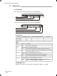
Gigabit Uplink Unmanaged Switch Appendix A Hardware Specifications Item Content IEEE802.3 10Base-T IEEE802.3u 100Base-TX Standards IEEE802.3ab 1000Base-T IEEE802.3z 1000Base-X (for TL-SL1351 only1 ANSI/IEEE Std 802.3 Nway IEEE802.3x 10Base-T: UTP/STP of Cat. 3 or above(maximum 100m1 Transmission Medium 100Base-TX: UTP/STP of Cat. 5 or above(maximum 100m1 1000Base-TX: UTP/STP of Cat.
Gigabit Uplink Unmanaged Switch Appendix B Technical Support ■■ For more troubleshooting help, go to: http://www.tp-link.com/en/support/faq ■■ To download the latest Firmware, Driver, Utility and User Guide, go to: http://www.tp-link.com/en/support/download ■■ 18 For all other technical support, please contact us by using the following details: Global Tel: +86 755 2650 4400 Fee: Depending on rate of different carriers, IDD. E-mail: support@tp-link.
Gigabit Uplink Unmanaged Switch Indonesia Tel: (+621 021 6386 1936 Fee: Depending on rate of different carriers. E-mail: support.id@tp-link.com Service time: Sunday to Friday, 09:00 to 12:00, 13:00 to 18:00 *Except public holidays France Tel: 0820 800 860 (French service1 Fee: 0.118 EUR/min from France Email: support.fr@tp-link.com Service time: Monday to Friday, 09:00 to 18:00 *Except French Bank holidays Australia/New Zealand Tel: NZ 0800 87 5465 (Toll Free1 AU 1300 87 5465 (Depending on 1300 policy.
Website: http://www.tp-link.com E-mail: support@tp-link.com 7106504623 Rev4.0.