TL-SL2218/TL-SL2428 Smart Switch Rev: 1.1.
COPYRIGHT & TRADEMARKS Specifications are subject to change without notice. is a registered trademark of TP-LINK TECHNOLOGIES CO., LTD. Other brands and product names are trademarks or registered trademarks of their respective holders. No part of the specifications may be reproduced in any form or by any means or used to make any derivative such as translation, transformation, or adaptation without permission from TP-LINK TECHNOLOGIES CO., LTD. Copyright © 2013 TP-LINK TECHNOLOGIES CO., LTD.
Safety Information z z z When product has power button, the power button is one of the way to shut off the product; When there is no power button, the only way to completely shut off power is to disconnect the product or the power adapter from the power source. Don’t disassemble the product, or make repairs yourself. You run the risk of electric shock and voiding the limited warranty. If you need service, please contact us. Avoid water and wet locations.
CONTENTS Package Contents ..........................................................................................................................1 Chapter 1 About this Guide ..........................................................................................................2 1.1 Intended Readers .........................................................................................................2 1.2 Conventions.................................................................................
.2 5.3 5.4 5.1.3 Port Security ....................................................................................................27 5.1.4 Port Isolation ....................................................................................................29 LAG ............................................................................................................................30 5.2.1 LAG Table ..................................................................................................
8.2 8.3 8.4 8.1.3 VLAN Config ....................................................................................................78 8.1.4 Multicast VLAN ................................................................................................80 Multicast IP .................................................................................................................83 8.2.1 Multicast IP Table .............................................................................................
11.3 11.4 11.2.1 Log Table .......................................................................................................121 11.2.2 Local Log .......................................................................................................122 11.2.3 Remote Log ...................................................................................................122 11.2.4 Backup Log ....................................................................................................
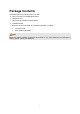
Package Contents The following items should be found in your box: ¾ One TL-SL2218 /TL-SL2428 Smart Switch ¾ One power cord ¾ Two mounting brackets and other fittings ¾ Installation Guide ¾ Resource CD for TL-SL2218 /TL-SL2428 Smart Switch, including: • This User Guide • Other Helpful Information Note: Make sure that the package contains the above items. If any of the listed items are damaged or missing, please contact your distributor.
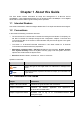
Chapter 1 About this Guide This User Guide contains information for setup and management of TL-SL2218 16-Port 10/100Mbps + 2-Port Gigabit Smart Switch and TL-SL2428 24-Port 10/100Mbps + 4-Port Gigabit Smart Switch. Please read this guide carefully before operation. 1.1 Intended Readers This Guide is intended for network managers familiar with IT concepts and network terminologies. 1.
Chapter Introduction Chapter 4 System This module is used to configure system properties of the switch. Here mainly introduces: z System Info: Configure the description, system time, Daylight Saving Time and network parameters of the switch. z User Management: Configure the user name and password for users to log on to the Web management page with a certain access level. z System Tools: Manage the configuration file of the switch.
Chapter Introduction Chapter 9 QoS This module is used to configure QoS function to provide different quality of service for various network applications and requirements. Here mainly introduces: z DiffServ: Configure priorities, port priority, 802.1P priority and DSCP priority. z Bandwidth Control: Configure rate limit feature to control the traffic rate on each port; configure storm control feature to filter broadcast, multicast and UL frame in the network.
Chapter 2 Introduction Thanks for choosing the TL-SL2218/TL-SL2428 Smart Switch! 2.1 Overview of the Switch Designed for workgroups and departments, TL-SL2218/TL-SL2428 from TP-LINK provides wire-speed performance and full set of layer 2 management features. They provide a variety of service features and multiple powerful functions with high security. The EIA-standardized framework and smart configuration capacity can provide flexible solutions for a variable scale of networks.
Figure 2-1 Front Panel of TL-SL2218 The front panel of TL-SL2428 is shown as Figure 2-2. Figure 2-2 Front Panel of TL-SL2428 The following parts are located on the front panel of the Switch: ¾ Reset: With the Switch powered on, press Reset button for five seconds to reset the software setting to its factory default settings. ¾ 10/100Mbps Ports: Designed to connect to the device with a bandwidth of 10Mbps or 100Mbps. Each has a corresponding 10/100M LED.
Note: When using the SFP port with a 100M module or a gigabit module, you need to log on to the GUI (Graphical User Interface) of the Switch and configure its corresponding Speed and Duplex mode on Switching→Port→Port Config page. For 100M module, please select 100MFD while select 1000MFD for gigabit module. By default, the Speed and Duplex mode of SFP port is 1000MFD. 2.3.2 Rear Panel The rear panel of TL-SL2218/TL-SL2428 features a power socket and a Grounding Terminal (marked with ).
Chapter 3 Login to the Switch 3.1 Login 1) To access the configuration utility, open a web-browser and type in the default address http://192.168.0.1 in the address field of the browser, then press the Enter key. Figure 3-1 Web-browser Tips: To log in to the Switch, the IP address of your PC should be set in the same subnet addresses of the Switch. The IP address is 192.168.0.x ("x" is any number from 2 to 254), Subnet Mask is 255.255.255.0.
Figure 3-3 Main Setup-Menu Note: Clicking Apply can only make the new configurations effective before the switch is rebooted. If you want to keep the configurations effective even the switch is rebooted, please click Save Config. You are suggested to click Save Config before cutting off the power or rebooting the switch to avoid losing the new configurations.
Chapter 4 System The System module is mainly for system configuration of the switch, including four submenus: System Info, User Management, System Tools and Access Security. 4.1 System Info The System Info, mainly for basic properties configuration, can be implemented on System Summary, Device Description, System Time, Daylight Saving Time and System IP pages. 4.1.1 System Summary On this page you can view the port connection status and the system information.
Indicates the 1000Mbps port is not connected to a device. Indicates the 1000Mbps port is at the speed of 1000Mbps. Indicates the 1000Mbps port is at the speed of 10Mbps or 100Mbps. Indicates the SFP port is not connected to a device. Indicates the SFP port is at the speed of 1000Mbps. Indicates the SFP port is at the speed of 100Mbps. When the cursor moves on the port, the detailed information of the port will be displayed.
Figure 4-3 Bandwidth Utilization ¾ Bandwidth Utilization Rx: Select Rx to display the bandwidth utilization of receiving packets on this port. Tx: Select Tx to display the bandwidth utilization of sending packets on this port. 4.1.2 Device Description On this page you can configure the description of the switch, including device name, device location and system contact. Choose the menu System→System Info→Device Description to load the following page.
Device Location: Enter the location of the switch. System Contact: Enter your contact information. 4.1.3 System Time System Time is the time displayed while the switch is running. On this page you can configure the system time and the settings here will be used for other time-based functions like ACL. You can manually set the system time, or synchronize with PC’s clock as the system time. Choose the menu System→System Info→System Time to load the following page.
Figure 4-6 System Time The following entries are displayed on this screen: DST Status: Enable or Disable the DST. Predefined Mode: Select a predefined DST configuration. z z z z Recurring Mode: Specify the DST configuration configuration is recurring in use. z z Date Mode: USA: First Sunday in April, 02:00 ~ Last Sunday in October, 02:00. Australia: First Sunday in October, 02:00 ~ First Sunday in April, 03:00. European: Last Sunday in March, 01:00 ~ Last Sunday in October, 01:00.
4.1.5 System IP Each device in the network possesses a unique IP Address. You can log on to the Web management page to operate the switch using this IP Address. The switch supports three modes to obtain an IP address: Static IP, DHCP and BOOTP. The IP address obtained using a new mode will replace the original IP address. On this page you can configure the system IP of the switch. Choose the menu System→System Info→System IP to load the following page.
Note: 3. Changing the IP address to a different IP segment will interrupt the network communication, so please keep the new IP address in the same IP segment with the local network. 4. The switch only possesses an IP address. The IP address configured will replace the original IP address. 5.
Figure 4-9 User Config The following entries are displayed on this screen: ¾ User Info User Name: Create a name for users’ login. Access Level: Select the access level to login. z z ¾ Admin: Admin can edit, modify and view all the settings of different functions. Guest: Guest only can view the settings without the right to edit and modify. User Status: Select Enable/Disable the user configuration. Password: Type a password for users’ login. Confirm Password: Retype the password.
4.3 System Tools The System Tools function, allowing you to manage the configuration file of the switch, can be implemented on Config Restore, Config Backup, Firmware Upgrade, System Reboot and System Reset pages. 4.3.1 Config Restore On this page you can upload a backup configuration file to restore your switch to this previous configuration. Choose the menu System→System Tools→Config Restore to load the following page.
Figure 4-11 Config Backup The following entries are displayed on this screen: ¾ Config Backup Backup Config: Click the Backup Config button to save the current configuration as a file to your computer. You are suggested to take this measure before upgrading. Note: It will take a few minutes to backup the configuration. Please wait without any operation. 4.3.3 Firmware Upgrade The switch system can be upgraded via the Web management page.
3. To avoid damage, please don't turn off the device while upgrading. 4. After upgrading, the device will reboot automatically. 5. You are suggested to backup the configuration before upgrading. 4.3.4 System Reboot On this page you can reboot the switch and return to the login page. Please save the current configuration before rebooting to avoid losing the configuration unsaved. Choose the menu System→System Tools→System Reboot to load the following page.
Figure 4-15 Access Control The following entries are displayed on this screen: ¾ Access Control Config Control Mode: Select the control mode for users to log on to the Web management page. z z z IP-based: Select this option to limit the IP-range of the users for login. MAC-based: Select this option to limit the MAC Address of the users for login. Port-based: Select this option to limit the ports for login.
¾ Session Config Session Timeout: ¾ If you do nothing with the Web management page within the timeout time, the system will log out automatically. If you want to reconfigure, please login again. Access User Number Number Control; Select Enable/Disable the Number Control function. Admin Number: Enter the maximum number of the users logging on to the Web management page as Admin. Guest Number: Enter the maximum number of the users logging on to the Web management page as Guest.
Chapter 5 Switching Switching module is used to configure the basic functions of the switch, including four submenus: Port, LAG, Traffic Monitor and MAC Address. 5.1 Port The Port function, allowing you to configure the basic features for the port, is implemented on the Port Config, Port Mirror, Port Security and Port Isolation pages. 5.1.1 Port Config On this page, you can configure the basic parameters for the ports. When the port is disabled, the packets on the port will be discarded.
Port: Displays the port number. Description: Give a description to the port for identification. Status: Allows you to Enable/Disable the port. When Enable is selected, the port can forward the packets normally. Speed and Duplex: Select the Speed and Duplex mode for the port. The device connected to the switch should be in the same Speed and Duplex mode with the switch. When “Auto” is selected, the Speed and Duplex mode will be determined by auto-negotiation.
Figure 5-2 Mirroring Port The following entries are displayed on this screen. ¾ Mirror Group List Group: Displays the mirror group number. Mirroring: Displays the mirroring port number. Mode: Displays the mirror mode, the value will be "Ingress" or "Egress", Mirrored Port: Displays the mirrored ports. Operation: Click Edit to configure the mirror group. Click Edit to display the following figure.
Figure 5-3 Mirroring Port The following entries are displayed on this screen. ¾ Mirror Group Number: ¾ Mirroring Port Mirroring Port: ¾ Select the mirror group number you want to configure. Select the mirroring port number. Mirrored Port Port Select: Click the Select button to quick-select the corresponding port based on the port number you entered. Select: Select the desired port as a mirrored port. It is multi-optional. Port: Displays the port number.
Egress: Select Enable/Disable the Egress feature. When the Egress is enabled, the outgoing packets sent by the mirrored port will be copied to the mirroring port. LAG: Displays the LAG number which the port belongs to. The LAG member can not be selected as the mirrored port or mirroring port. Note: 1. The LAG member can not be selected as the mirrored port or mirroring port. 2. A port can not be set as the mirrored port and the mirroring port simultaneously. 3.
Figure 5-4 Port Security The following entries are displayed on this screen: ¾ Port Security Select: Select the desired port for Port Security configuration. It is multi-optional. Port: Displays the port number. Max Learned MAC: Specify the maximum number of MAC addresses that can be learned on the port. Learned Num: Displays the number of MAC addresses that have been learned on the port. Learn Mode: Select the Learn Mode for the port.
Note: The Port Security function is disabled for the LAG port member. Only the port is removed from the LAG, will the Port Security function be available for the port. 5.1.4 Port Isolation Port Isolation provides a method of restricting traffic flow to improve the network security by forbidding the port to forward packets to the ports that are not on its forward portlist. Choose the menu Switching→Port→Port Isolation to load the following page.
¾ Port Isolation List Port: Display the port number. Forward Portlist: Display the forwardlist. 5.2 LAG LAG (Link Aggregation Group) is to combine a number of ports together to make a single high-bandwidth data path, so as to implement the traffic load sharing among the member ports in the group and to enhance the connection reliability. For the member ports in an aggregation group, their basic configuration must be the same.
Figure 5-6 LAG Table The following entries are displayed on this screen: ¾ Global Config Hash Algorithm: Select the applied scope of Aggregate Arithmetic, which results in choosing a port to transfer the packets. • SRC MAC + DST MAC: When this option is selected, the Aggregate Arithmetic will apply to the source and destination MAC addresses of the packets. • SRC IP + DST IP: When this option is selected, the Aggregate Arithmetic will apply to the source and destination IP addresses of the packets.
Figure 5-7 Detail Information 5.2.2 Static LAG On this page, you can manually configure the LAG. Choose the menu Switching→LAG→Static LAG to load the following page. Figure 5-8 Static LAG The following entries are displayed on this screen: ¾ LAG Config Group Number: Select a Group Number for the LAG. Description: Displays the description of LAG.
¾ Member Port Member Port: Select the port as the LAG member. Clearing all the ports of the LAG will delete this LAG. Tips: The LAG can be deleted by clearing its all member ports. 5.3 Traffic Monitor The Traffic Monitor function, monitoring the traffic of each port, is implemented on the Traffic Summary and Traffic Statistics pages. 5.3.1 Traffic Summary Traffic Summary screen displays the traffic information of each port, which facilitates you to monitor the traffic and analyze the network abnormity.
Refresh Rate: ¾ Enter a value in seconds to specify the refresh interval. Traffic Summary Port Select: Click the Select button to quick-select the corresponding port based on the port number you entered. Port: Displays the port number. Packets Rx: Displays the number of packets received on the port. The error packets are not counted in. Packets Tx: Displays the number of packets transmitted on the port. Octets Rx: Displays the number of octets received on the port.
The following entries are displayed on this screen: ¾ ¾ Auto Refresh Auto Refresh: Allows you to Enable/Disable refreshing the Traffic Summary automatically. Refresh Rate: Enter a value in seconds to specify the refresh interval. Statistics Port: Enter a port number and click the Select button to view the traffic statistics of the corresponding port. Received: Displays the details of the packets received on the port. Sent: Displays the details of the packets transmitted on the port.
5.4 MAC Address The main function of the switch is forwarding the packets to the correct ports based on the destination MAC address of the packets. Address Table contains the port-based MAC address information, which is the base for the switch to forward packets quickly. The entries in the Address Table can be updated by auto-learning or configured manually. Most the entries are generated and updated by auto-learning.
Figure 5-11 Address Table The following entries are displayed on this screen: ¾ Search Option MAC Address: Enter the MAC address of your desired entry. VLAN ID: Enter the VLAN ID of your desired entry. Port: Select the corresponding port number of your desired entry. Type: Select the type of your desired entry. z z z z ¾ All: This option allows the address table to display all the address entries. Static: This option allows the address table to display the static address entries only.
5.4.2 Static Address The static address table maintains the static address entries which can be added or removed manually, independent of the aging time. In the stable networks, the static MAC address entries can facilitate the switch to reduce broadcast packets and remarkably enhance the efficiency of packets forwarding without learning the address. The static MAC address learned by the port with Port Security enabled in the static learning mode will be displayed in the Static Address Table.
¾ Static Address Table Select: Select the entry to delete or modify the corresponding port number. It is multi-optional. MAC Address: Displays the static MAC Address. VLAN ID: Displays the corresponding VLAN ID of the MAC address. Port: Displays the corresponding Port number of the MAC address. Here you can modify the port number to which the MAC address is bound. The new port should be in the same VLAN. Type: Displays the Type of the MAC address.
Figure 5-13 Dynamic Address The following entries are displayed on this screen: ¾ ¾ Aging Config Auto Aging: Allows you to Enable/Disable the Auto Aging feature. Aging Time: Enter the Aging Time for the dynamic address. Search Option Search Option: ¾ Select a Search Option from the pull-down list and click the Search button to find your desired entry in the Dynamic Address Table. • MAC: Enter the MAC address of your desired entry. • VLAN ID: Enter the VLAN ID number of your desired entry.
Type: Displays the Type of the MAC address. Aging Status: Displays the Aging Status of the MAC address. Bind: Click the Bind button to bind the MAC address of your selected entry to the corresponding port statically. Tips: Setting aging time properly helps implement effective MAC address aging. The aging time that is too long or too short results decreases the performance of the switch.
VLAN ID: ¾ Search Option Search Option: ¾ Enter the corresponding VLAN ID of the MAC address. Select a Search Option from the pull-down list and click the Search button to find your desired entry in the Filtering Address Table. • MAC: Enter the MAC address of your desired entry. • VLAN ID: Enter the VLAN ID number of your desired entry. Filtering Address Table Select: Select the entry to delete the corresponding filtering address. It is multi-optional.
Chapter 6 VLAN The traditional Ethernet is a data network communication technology basing on CSMA/CD (Carrier Sense Multiple Access/Collision Detect) via shared communication medium. Through the traditional Ethernet, the overfull hosts in LAN will result in serious collision, flooding broadcasts, poor performance or even breakdown of the Internet.
matched, the switch will add a corresponding VLAN tag to it and forward it in the corresponding VLAN. 6.1 802.1Q VLAN VLAN tags in the packets are necessary for the switch to identify packets of different VLANs. The switch works at the data link layer in OSI model and it can identify the data link layer encapsulation of the packet only, so you can add the VLAN tag field into the data link layer encapsulation for identification. In 1999, IEEE issues the IEEE 802.
(2) TRUNK: The TRUNK port can be added in multiple VLANs, and the egress rule of the port is TAG. The TRUNK port is generally used to connect the cascaded network devices for it can receive and forward the packets of multiple VLANs. When the packets are forwarded by the TRUNK port, its VLAN tag will not be changed. (3) GENERAL: The GENERAL port can be added in multiple VLANs and set various egress rules according to the different VLANs. The default egress rule is UNTAG.
6.1.1 VLAN Config On this page, you can view the current created 802.1Q VLAN. Choose the menu VLAN→802.1Q VLAN→VLAN Config to load the following page. Figure 6-3 VLAN Table To ensure the normal communication of the factory switch, the default VLAN of all ports is set to VLAN1. VLAN1 can not be modified or deleted. The following entries are displayed on this screen: ¾ VLAN Table VLAN ID Select: Click the Select button to quick-select the corresponding entry based on the VLAN ID number you entered.
Figure 6-4 Create or Modify 802.1Q VLAN The following entries are displayed on this screen: ¾ ¾ VLAN Config VLAN ID: Enter the ID number of VLAN. Description: Give a description to the VLAN for identification. VLAN Members Port Select: Click the Select button to quick-select the corresponding entry based on the port number you entered. Select: Select the desired port to be a member of VLAN or leave it blank. It's multi-optional. Port: Displays the port number.
Egress Rule: LAG: Select the Egress Rule for the VLAN port member. The default egress rule is UNTAG. • TAG: All packets forwarded by the port are tagged. The packets contain VLAN information. • UNTAG: Packets forwarded by the port are untagged. Displays the LAG to which the port belongs. 6.1.2 Port Config Before creating the 802.1Q VLAN, please acquaint yourself with all the devices connected to the switch in order to configure the ports properly. Choose the menu VLAN→802.
Link Type: Select the Link Type from the pull-down list for the port. • ACCESS: The ACCESS port can be added in a single VLAN, and the egress rule of the port is UNTAG. The PVID is same as the current VLAN ID. If the current VLAN is deleted, the PVID will be set to 1 by default. • TRUNK: The TRUNK port can be added in multiple VLANs, and the egress rule of the port is TAG. The PVID can be set as the VID number of any VLAN the port belongs to.
Configuration procedure: Step Operation Description 1 Set the link type for port. Required. On the VLAN→802.1Q VLAN→Port Config page, set the link type for the port basing on its connected device. 2 Create VLAN. Required. On the VLAN→802.1Q VLAN→VLAN Config page, click the Create button to create a VLAN. Enter the VLAN ID and the description for the VLAN. Meanwhile, specify its member ports. 3 Modify/View VLAN. Optional. On the VLAN→802.
Configuration Procedure ¾ Configure Switch A z Step Operation Description 1 Configure the Link Type of the ports Required. On VLAN→802.1Q VLAN→Port Config page, configure the link type of Port 2, Port 3 and Port 4 as ACCESS, TRUNK and ACCESS respectively 2 Create VLAN10 Required. On VLAN→802.1Q VLAN→VLAN Config page, create a VLAN with its VLANID as 10, owning Port 2 and Port 3. 3 Create VLAN20 Required. On VLAN→802.
Chapter 7 Spanning Tree STP (Spanning Tree Protocol), subject to IEEE 802.1D standard, is to disbranch a ring network in the Data Link layer in a local network. Devices running STP discover loops in the network and block ports by exchanging information, in that way, a ring network can be disbranched to form a tree-topological ring-free network to prevent packets from being duplicated and forwarded endlessly in the network. BPDU (Bridge Protocol Data Unit) is the protocol data that STP and RSTP use.
z Port: Port 3 is the root port of switch B and port 5 is the root port of switch C; port 1 is the designated port of switch A and port 4 is the designated port of switch B; port 6 is the blocked port of switch C. Figure 7-1 Basic STP diagram ¾ STP Timers Hello Time: Hello Time ranges from 1 to 10 seconds. It specifies the interval to send BPDU packets. It is used to test the links. Max. Age: Max. Age ranges from 6 to 40 seconds.
¾ z STP Generation In the beginning In the beginning, each switch regards itself as the root, and generates a configuration BPDU for each port on it as a root, with the root path cost being 0, the ID of the designated bridge being that of the switch, and the designated port being itself. z Comparing BPDUs Each switch sends out configuration BPDUs and receives a configuration BPDU on one of its ports from another switch. The following table shows the comparing operations.
Tips: In a STP with stable topology, only the root port and designated port can forward data, and the other ports are blocked. The blocked ports only can receive BPDUs. RSTP (Rapid Spanning Tree Protocol), evolved from the 802.1D STP standard, enable Ethernet ports to transit their states rapidly. The premises for the port in the RSTP to transit its state rapidly are as follows.
Figure 7-2 Basic MSTP diagram ¾ MSTP MSTP divides a network into several MST regions. The CST is generated between these MST regions, and multiple spanning trees can be generated in each MST region. Each spanning tree is called an instance. As well as STP, MSTP uses BPDUs to generate spanning tree. The only difference is that the BPDU for MSTP carries the MSTP configuration information on the switches.
Figure 7-3 Port roles The Spanning Tree module is mainly for spanning tree configuration of the switch, including four submenus: STP Config, Port Config, MSTP Instance and STP Security. 7.1 STP Config The STP Config function, for global configuration of spanning trees on the switch, can be implemented on STP Config and STP Summary pages. 7.1.1 STP Config Before configuring spanning trees, you should make clear the roles each switch plays in each spanning tree instance.
Figure 7-4 STP Config The following entries are displayed on this screen: ¾ Global Config STP: Select Enable/Disable STP function globally on the switch. Version: Select the desired STP version on the switch. z STP: Spanning Tree Protocol. z RSTP: Rapid Spanning Tree Protocol. z MSTP: Multiple Spanning Tree Protocol. ¾ Parameters Config CIST Priority: Enter a value from 0 to 61440 to specify the priority of the switch for comparison in the CIST.
5pps. Max Hops: Enter a value from 1 to 40 to set the maximum number of hops that occur in a specific region before the BPDU is discarded. The default value is 20 hops. Note: 1. The forward delay parameter and the network diameter are correlated. A too small forward delay parameter may result in temporary loops. A too large forward delay may cause a network unable to resume the normal state in time. The default value is recommended. 2.
Figure 7-5 STP Summary 7.2 Port Config On this page you can configure the parameters of the ports for CIST Choose the menu Spanning Tree→Port Config to load the following page.
Figure 7-6 Port Config The following entries are displayed on this screen: ¾ Port Config Port Select: Click the Select button to quick-select the corresponding port based on the port number you entered. Select: Select the desired port for STP configuration. It is multi-optional. Port: Displays the port number of the switch. Status: Select Enable /Disable STP function for the desired port. Priority: Enter a value from 0 to 240 divisible by 16.
z z z z z z Port Status: Displays the working status of the port. z z z z LAG: Root Port: Indicates the port that has the lowest path cost from this bridge to the Root Bridge and forwards packets to the root. Designated Port: Indicates the port that forwards packets to a downstream network segment or switch. Master Port: Indicates the port that connects a MST region to the common root. The path from the master port to the common root is the shortest path between this MST region and the common root.
Figure 7-7 Region Config The following entries are displayed on this screen: ¾ Region Config Region Name: Create a name for MST region identification using up to 32 characters. Revision: Enter the revision from 0 to 65535 for MST region identification. 7.3.2 Instance Config Instance Configuration, a property of MST region, is used to describe the VLAN to Instance mapping configuration. You can assign VLAN to different instances appropriate to your needs.
The following entries are displayed on this screen: ¾ ¾ Instance Table Instance ID Select: Click the Select button to quick-select the corresponding Instance ID based on the ID number you entered. Select: Select the desired Instance ID for configuration. It is multi-optional. Instance: Displays Instance ID of the switch. Status: Select Enable/Disable the instance. Priority: Enter the priority of the switch in the instance.
Figure 7-9 Instance Port Config The following entries are displayed on this screen: ¾ Port Config Instance ID: Select the desired instance ID for its port configuration. Port Select: Click the Select button to quick-select the corresponding port based on the port number you entered. Select: Select the desired port to specify its priority and path cost. It is multi-optional. Port: Displays the port number of the switch. Priority: Enter the priority of the port in the instance.
LAG: Displays the LAG number which the port belongs to. Note: The port status of one port in different spanning tree instances can be different. Global configuration Procedure for Spanning Tree function: Step Operation Description 1 Make clear roles the switches play in spanning tree instances: root bridge or designated bridge Preparation. 2 Globally configure parameters MSTP Required.
packets from the upstream switch and spanning trees are regenerated, and thereby loops can be prevented. ¾ Root Protect A CIST and its secondary root bridges are usually located in the high-bandwidth core region. Wrong configuration or malicious attacks may result in configuration BPDU packets with higher priorities being received by the legal root bridge, which causes the current legal root bridge to lose its position and network topology jitter to occur.
Figure 7-10 Port Protect The following entries are displayed on this screen: ¾ Port Protect Port Select: Click the Select button to quick-select the corresponding port based on the port number you entered. Select: Select the desired port for port protect configuration. It is multi-optional. Port: Displays the port number of the switch. Loop Protect: Loop Protect is to prevent the loops in the network brought by recalculating STP because of link failures and network congestions.
7.4.2 TC Protect When TC Protect is enabled for the port on Port Protect page, the TC threshold and TC protect cycle need to be configured on this page. Choose the menu Spanning Tree→STP Security→TC Protect to load the following page. Figure 7-11 TC Protect The following entries are displayed on this screen: ¾ TC Protect TC Threshold: Enter a number from 1 to 100. It is the maximum number of the TC-BPDUs received by the switch in a TC Protect Cycle. The default value is 20.
Configuration Procedure ¾ z Configure Switch A: Step Operation Description 1 Configure ports On VLAN→802.1Q VLAN page, configure the link type of the related ports as Trunk, and add the ports to VLAN101-VLAN106. The detailed instructions can be found in the section 802.1Q VLAN. 2 Enable STP function On Spanning Tree→STP Config→STP Config page, enable STP function and select MSTP version. On Spanning Tree→STP Config→Port Config page, enable MSTP function for the port.
z Configure Switch C: Step Operation Description 1 Configure ports On VLAN→802.1Q VLAN page, configure the link type of the related ports as Trunk, and add the ports to VLAN101-VLAN106. The detailed instructions can be found in the section 802.1Q VLAN. 2 Enable STP function On Spanning Tree→STP Config→STP Config page, enable STP function and select MSTP version. On Spanning Tree→STP Config→Port Config page, enable MSTP function for the port.
¾ The topology diagram of the two instances after the topology is stable z For Instance 1 (VLAN 101, 103 and 105), the red paths in the following figure are connected links; the gray paths are the blocked links. z For Instance 2 (VLAN 102, 104 and 106), the blue paths in the following figure are connected links; the gray paths are the blocked links. ¾ Suggestion for Configuration z Enable TC Protect function for all the ports of switches.
Chapter 8 Multicast ¾ Multicast Overview In the network, packets are sent in three modes: unicast, broadcast and multicast. In unicast, the source server sends separate copy information to each receiver. When a large number of users require this information, the server must send many pieces of information with the same content to the users. Therefore, large bandwidth will be occupied. In broadcast, the system transmits information to all users in a network.
4. Real time is highly demanded and certain packets drop is allowed. ¾ Multicast Address 1. Multicast IP Address: As specified by IANA (Internet Assigned Numbers Authority), Class D IP addresses are used as destination addresses of multicast packets. The multicast IP addresses range from 224.0.0.0~239.255.255.255. The following table displays the range and description of several special multicast IP addresses. Multicast IP address range Description 224.0.0.0~224.0.0.
should be a group port list, so the switch will duplicate this multicast data and deliver each port one copy. The general format of the multicast address table is described as Figure 8-3 below. VLAN ID Multicast IP Port Figure 8-3 Multicast Address Table ¾ IGMP Snooping In the network, the hosts apply to the near Router for joining (leaving) a multicast group by sending IGMP (Internet Group Management Protocol) messages.
When receiving IGMP report message, the switch will send the report message via the router port in the VLAN as well as analyze the message to get the address of the multicast group the host applies for joining. The receiving port will be processed: if the receiving port is a new member port, it will be added to the multicast address table with its member port time specified; if the receiving port is already a member port, its member port time will be directly reset. 3.
Figure 8-4 Basic Config The following entries are displayed on this screen: ¾ ¾ Global Config IGMP Snooping: Select Enable/Disable IGMP Snooping function globally on the Switch. Unknown Multicast: Select the operation for the switch to process unknown multicast, Forward or Discard. IGMP Snooping Status Description: Displays IGMP Snooping status. Member: Displays the member of the corresponding status. 8.1.2 Port Config On this page you can configure the IGMP feature for ports of the switch.
Figure 8-5 Port Config The following entries are displayed on this screen: ¾ Port Config Port Select: Click the Select button to quick-select the corresponding port based on the port number you entered. Select: Select the desired port for IGMP Snooping feature configuration. It is multi-optional. Port: Displays the port of the Switch. IGMP Snooping: Select Enable/Disable IGMP Snooping for the desired port. Fast Leave: Select Enable/Disable Fast Leave feature for the desired port.
Choose the menu Multicast→IGMP Snooping→VLAN Config to load the following page. Figure 8-6 VLAN Config The following entries are displayed on this screen: ¾ ¾ VLAN Config VLAN ID: Enter the VLAN ID to enable IGMP Snooping for the desired VLAN. Router Port Time: Specify the aging time of the router port. Within this time, if the switch doesn’t receive IGMP query message from the router port, it will consider this port is not a router port any more.
Member Port Time: Displays the member port time of the VLAN. Leave Time: Displays the leave time of the VLAN. Router Port: Displays the router port of the VLAN. Note: The settings here will be invalid when multicast VLAN is enabled Configuration procedure: Step Operation 1 Enable function Snooping Required. Enable IGMP Snooping globally on the switch and for the port on Multicast→IGMP Snooping→Snooping Config and Port Config page. 2 Configure the multicast parameters for VLANs Optional.
Figure 8-7 Multicast VLAN The following entries are displayed on this screen: ¾ Multicast VLAN Multicast VLAN: Select Enable/Disable Multicast VLAN feature. VLAN ID: Enter the VLAN ID of the multicast VLAN. Router Port Time: Specify the aging time of the router port. Within this time, if the switch doesn’t receive IGMP query message from the router port, it will consider this port is not a router port any more. Member Port Time: Specify the aging time of the member port.
5. After a multicast VLAN is created, all the IGMP packets will be processed only within the multicast VLAN. Configuration procedure: Step Operation 1 Enable IGMP function 2 Create a multicast VLAN 3 Description Snooping Configure parameters multicast VLAN Required. Enable IGMP Snooping globally on the switch and for the port on Multicast→IGMP Snooping→Snooping Config and Port Config page. Required. Create a multicast VLAN and add all the member ports and router ports to the VLAN on the VLAN→802.
¾ Configuration Procedure Step Operation Description 1 Create VLANs Create three VLANs with the VLAN ID 3, 4 and 5 respectively, and specify the description of VLAN3 as Multicast VLAN on VLAN→802.1Q VLAN page. 2 Configure ports On VLAN→802.1Q VLAN function pages. For port 3, configure its link type as GENERAL and its egress rule as TAG, and add it to VLAN3, VLAN4 and VLAN5. For port 4, configure its link type as GENERAL and its egress rule as UNTAG, and add it to VLAN3 and VLAN 4.
8.2.1 Multicast IP Table On this page you can view the multicast IP table on the switch. Choose the menu Multicast→Multicast IP→Multicast IP Table to load the following page. Figure 8-8 Multicast IP Table The following entries are displayed on this screen: ¾ Search Option Multicast IP: Enter the multicast IP address the desired entry must carry. VLAN ID: Enter the VLAN ID the desired entry must carry. Port: Select the port number the desired entry must carry.
Choose the menu Multicast→Multicast IP→Static Multicast IP to load the following page. Figure 8-9 Static Multicast IP Table The following entries are displayed on this screen: ¾ ¾ Create Static Multicast Multicast IP: Enter static multicast IP address. VLAN ID: Enter the VLAN ID of the multicast IP. Forward Port: Enter the forward port of the multicast group. Search Option Search Option: ¾ Select the rules for displaying multicast IP table to find the desired entries quickly.
When applying for a multicast group, the host will send IGMP report message. After receiving the report message, the switch will firstly check the multicast filter rules configured for the receiving port. If the port can be added to the multicast group, it will be added to the multicast address table; if the port can not be added to the multicast group, the switch will drop the IGMP report message.
8.3.2 Port Filter On this page you can configure the multicast filter rules for port. Take the configuration on this page and the configuration on IP-Range page together to function to implement multicast filter function on the switch. Choose the menu Multicast→Multicast Filter→Port Filter to load the following page.
LAG: Displays the LAG number which the port belongs to. Note: 1. Multicast Filter feature can only have effect on the VLAN with IGMP Snooping enabled. 2. Multicast Filter feature has no effect on static multicast IP. 3. Up to 15 IP-Ranges can be bound to one port. Configuration Procedure: Step Operation Description 1 Configure IP-Range Required. Configure IP-Range to be Multicast→Multicast Filter→IP-Range page. 2 Configure multicast filter rules for ports Optional.
The following entries are displayed on this screen: ¾ ¾ Auto Refresh Auto Refresh: Select Enable/Disable auto refresh feature. Refresh Period: Enter the time from 3 to 300 in seconds to specify the auto refresh period. IGMP Statistics Port Select: Click the Select button to quick-select the corresponding port based on the port number you entered. Port: Displays the port number of the switch. Query Packet: Displays the number of query packets the port received.
Chapter 9 QoS QoS (Quality of Service) functions to provide different quality of service for various network applications and requirements and optimize the bandwidth resource distribution so as to provide a network service experience of a better quality. ¾ QoS This switch classifies the ingress packets, maps the packets to different priority queues and then forwards the packets according to specified scheduling algorithms to implement QoS function.
2. 802.1P Priority Figure 9-2 802.1Q frame As shown in the figure above, each 802.1Q Tag has a Pri field, comprising 3 bits. The 3-bit priority field is 802.1p priority in the range of 0 to 7. 802.1P priority determines the priority of the packets based on the Pri value. On the Web management page of the switch, you can configure different priority tags mapping to the corresponding priority levels, and then the switch determine which packet is sent preferentially when forwarding packets.
Figure 9-4 SP-Mode 2. WRR-Mode: Weight Round Robin Mode. In this mode, packets in all the queues are sent in order based on the weight value for each queue and every queue can be assured of a certain service time. The weight value indicates the occupied proportion of the resource. WRR queue overcomes the disadvantage of SP queue that the packets in the queues with lower priority can not get service for a long time.
4. Equ-Mode: Equal-Mode. In this mode, all the queues occupy the bandwidth equally. The weight value ratio of all the queues is 1:1:1:1. The QoS module is mainly for traffic control and priority configuration, including two submenus: DiffServ and Bandwidth Control. 9.1 DiffServ This switch classifies the ingress packets, maps the packets to different priority queues and then forwards the packets according to specified scheduling algorithms to implement QoS function.
Priority: Specify the priority for the port. LAG: Displays the LAG number which the port belongs to. Note: To complete QoS function configuration, you have to go to the Schedule Mode page to select a schedule mode after the configuration is finished on this page. Configuration Procedure: Step Operation Description 1 Log on to the Port Priority page 2 Select the desired ports for configuration Select the desired ports. It is multi-optional. 3 Select the port priority Required.
802.1P Priority Config ¾ 802.1P Priority: Select Enable/Disable 802.1P Priority. Priority Level ¾ Tag-id/CoS-id: Indicates the precedence level defined by IEEE802.1P and the CoS ID Queue TC-id: Indicates the priority level of egress queue the packets with tag and CoS-id are mapped to.
Figure 9-8 DSCP Priority The following entries are displayed on this screen: ¾ DSCP Priority Config DSCP Priority: ¾ Select Enable or Disable DSCP Priority. Priority Level DSCP: Indicates the priority determined by the DS region of IP datagram. It ranges from 0 to 63. Priority Level: Indicates the priority level the packets with tag are mapped to. The priority levels are labeled as TC0, TC1, TC2 and TC3.
Configuration procedure: Step Operation Description 1 Log on to the DSCP Priority page 2 Enable DP priority function Required. By default, the DSCP priority function is disabled. 3 Map the DSCP priority to the priority level Required. Select DSCP priority and the corresponding priority level. 4 Select a schedule mode Required. Log on to the Schedule Mode page to select a schedule mode. 9.1.4 Schedule Mode On this page you can select a schedule mode for the switch.
SP+WRR-Mode: Strict-Priority + Weight Round Robin Mode. In this mode, this switch provides two scheduling groups, SP group and WRR group. Queues in SP group and WRR group are scheduled strictly based on strict-priority mode while the queues inside WRR group follow the WRR mode. In SP+WRR mode, TC3 is in the SP group; TC0, TC1 and TC2 belong to the WRR group and the weight value ratio of TC0, TC1 and TC2 is 1:2:4.
Figure 9-10 Rate Limit The following entries are displayed on this screen: ¾ Rate Limit Config Port Select: Click the Select button to quick-select the corresponding port based on the port number you entered. Select: Select the desired port for Rate configuration. It is multi-optional. Port: Displays the port number of the Switch. Ingress Rate(Kbps): Configure the bandwidth for receiving packets on the port.
Note: 1. If you enable ingress rate limit feature for the storm control-enabled port, storm control feature will be disabled for this port. 2. When selecting "Manual" to set Ingress/Egress rate, the system will automatically select integral multiple of 64Kbps that closest to the rate you entered as the real Ingress/Egress rate. For example, if you enter 1023Kbps for egress rate, the system will automatically select 1024Kbps as the real Egress rate. 3.
Select: Select the desired port for Storm Control configuration. It is multi-optional. Port: Displays the port number of the Switch. Broadcast Rate (bps): Enable/Disable broadcast control feature for the port. Multicast Rate (bps): Enable/Disable multicast control feature for the port. UL-Frame Rate (bps): Enable/Disable UL-Frame control feature for the port. LAG: Displays the LAG number which the port belongs to.
Chapter 10 SNMP ¾ SNMP Overview SNMP (Simple Network Management Protocol) has gained the most extensive application on the UDP/IP networks. SNMP provides a management frame to monitor and maintain the network devices. It is used for automatically managing the various network devices no matter the physical differences of the devices. Currently, the most network management systems are based on SNMP.
normally. You can select the management mode with proper security level according to your actual application requirement. SNMP v1: SNMP v1 adopts Community Name authentication. The community name is used to define the relation between SNMP Management Station and SNMP Agent. The SNMP packets that fail to pass community name authentication are discarded. The community name can limit access to SNMP Agent from SNMP NMS, functioning as a password. SNMP v2c: SNMP v2c also adopts community name authentication.
network access by providing the users in various groups with different management rights via the Read View, Write View and Notify View. 3. Create SNMP User The User configured in a SNMP Group can manage the switch via the client program on management station. The specified User Name and the Auth/Privacy Password are used for SNMP Management Station to access the SNMP Agent, functioning as the password.
¾ Remote Engine Remote Engine ID: Specify the Remote Engine ID for Switch. The Engine ID is a unique alphanumeric string used to identify the SNMP engine on the remote device which receives informs from Switch. Note: The amount of Engine ID characters must be even. 10.1.2 SNMP View The OID (Object Identifier) of the SNMP packets is used to describe the managed objects of the switch, and the MIB (Management Information Base) is the set of the OIDs.
¾ View Table Select: Select the desired entry to delete the corresponding view. All the entries of a View will be deleted together. View Name: Displays the name of the View entry. View Type: Displays the type of the View entry. MIB Object ID: Displays the OID of the View entry. 10.1.3 SNMP Group On this page, you can configure SNMP Group to control the network access by providing the users in various groups with different management rights via the Read View, Write View and Notify View.
Security Model: Security Level: ¾ Select the Security Model for the SNMP Group. • v1: SNMPv1 is defined for the group. In this model, the Community Name is used for authentication. SNMP v1 can be configured on the SNMP Community page directly. • v2c: SNMPv2c is defined for the group. In this model, the Community Name is used for authentication. SNMP v2c can be configured on the SNMP Community page directly. • v3: SNMPv3 is defined for the group.
10.1.4 SNMP User The User in a SNMP Group can manage the switch via the management station software. The User and its Group have the same security level and access right. You can configure the SNMP User on this page. Choose the menu SNMP→SNMP Config→SNMP User to load the following page. Figure 10-6 SNMP User The following entries are displayed on this screen: ¾ User Config User Name: Enter the User Name here. User Type: Select the type for the User.
a higher security than MD5 mode. Auth Password: Enter the password for authentication. Privacy Mode: Select the Privacy Mode for the SNMP v3 User. Privacy Password: ¾ • None: No privacy method is used. • DES: DES encryption method is used. Enter the Privacy Password. User Table Select: Select the desired entry to delete the corresponding User. It is multi-optional. User Name: Displays the name of the User. User Type: Displays the User Type. Group Name: Displays the Group Name of the User.
Figure 10-7 SNMP Community The following entries are displayed on this screen: ¾ Community Config Community Name: Enter the Community Name here. Access: Defines the access rights of the community. MIB View: ¾ • read-only: Management right of the Community is restricted to read-only, and changes cannot be made to the corresponding View. • read-write: Management right of the Community is read-write and changes can be made to the corresponding View. Select the MIB View for the community to access.
Step Operation Description 1 Enable SNMP function globally. Required. On the SNMP→SNMP Config→Global Config page, enable SNMP function globally. 2 Create SNMP View. Required. On the SNMP→SNMP Config→SNMP View page, create SNMP View of the management agent. The default View Name is viewDefault and the default OID is 1. 3 Create SNMP Group. Required. On the SNMP→SNMP Config→SNMP Group page, create SNMP Group for SNMPv3 and specify SNMP Views with various access levels for SNMP Group.
Trap : Trap is the information that the managed device initiatively sends to the Network management station without request. Inform:Inform packet is sent to inform the management station and ask for the reply. The switch will resend the inform request if it doesn’t get the response from the management station during the Timeout interval, and it will terminate resending the inform request if the resending times reach the specified Retry times.
higher security than the Trap type. ¾ Retry: Specify the amount of times the switch resends an inform request. The switch will resend the inform request if it doesn’t get the response from the management station during the Timeout interval, and it will terminate resending the inform request if the resending times reach the specified Retry times. Timeout: Specify the maximum time for the switch to wait for the response from the management station before resending a request.
RMON Group Function History Group After a history group is configured, the switch collects and records network statistics information periodically, based on which the management station can monitor network effectively. Event Group Event Group is used to define RMON events. Alarms occur when an event is detected. Statistic Group Statistic Group is set to monitor the statistic of alarm variables on the specific ports. Alarm Group Alarm Group is configured to monitor the specific alarm variables.
Owner: Enter the name of the device or user that defined the entry. Status: Select Enable/Disable the corresponding sampling entry. 10.3.2 Event Config On this page, you can configure the RMON events. Choose the menu SNMP→RMON→Event Config to load the following page. Figure 10-10 Event Config The following entries are displayed on this screen: ¾ Event Table Select: Select the desired entry for configuration. Index: Displays the index number of the entry.
10.3.3 Alarm Config On this page, you can configure Statistic Group and Alarm Group for RMON. Choose the menu SNMP→RMON→Alarm Config to load the following page. Figure 10-11 Alarm Config The following entries are displayed on this screen: ¾ Alarm Table Select: Select the desired entry for configuration. Index: Displays the index number of the entry. Variable: Select the alarm variables from the pull-down list. Port: Select the port on which the Alarm entry acts.
• All: The alarm event will be triggered either the sampled value exceeds the Rise Hold or is under the Fall Hold. • Rising: When the sampled value exceeds the Rising Threshold, an alarm event is triggered. • Falling: When the sampled value is under the Falling Threshold, an alarm event is triggered. Interval: Enter the alarm interval time in seconds. Owner: Enter the name of the device or user that defined the entry. Status: Select Enable/Disable the corresponding alarm entry.
Chapter 11 Maintenance Maintenance module, assembling the commonly used system tools to manage the switch, provides the convenient method to locate and solve the network problem. (1) System Monitor: Monitor the utilization status of the memory and the CPU of switch. (2) Log: View the configuration parameters of the switch and find out the errors via the Logs. (3) Cable Test: Test the connection status of the cable to locate and diagnose the trouble spot of the network.
Figure 11-1 CPU Monitor Click the Monitor button to enable the switch to monitor and display its CPU utilization rate every four seconds. 11.1.2 Memory Monitor Choose the menu Maintenance→System Monitor→Memory Monitor to load the following page.
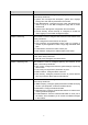
Figure 11-2 Memory Monitor Click the Monitor button to enable the switch to monitor and display its Memory utilization rate every four seconds. 11.2 Log The Log system of switch can record, classify and manage the system information effectively, providing powerful support for network administrator to monitor network operation and diagnose malfunction. The Logs of switch are classified into the following eight levels. Severity Level Description emergencies 0 The system is unusable.
The Log function is implemented on the Log Table, Local Log, Remote Log and Backup Log pages. 11.2.1 Log Table The switch supports logs output to two directions, namely, log buffer and log file. The information in log buffer will be lost after the switch is rebooted or powered off whereas the information in log file will be kept effective even the switch is rebooted or powered off. Log Table displays the system log information in log buffer.
11.2.2 Local Log Local Log is the log information saved in switch. By default, all system logs are saved in log buffer and the logs with severities from level_0 to level_4 are saved in log file meanwhile. On this page, you can set the output channel for logs. Choose the menu Maintenance→Log→Local Log to load the following page. Figure 11-4 Local Log The following entries are displayed on this screen: ¾ Local Log Config Select: Select the desired entry to configure the corresponding local log.
Figure 11-5 Log Host The following entries are displayed on this screen: ¾ Log Host Index: Displays the index of the log host. The switch supports 4 log hosts. Host IP: Configure the IP for the log host. UDP Port: Displays the UDP port used for receiving/sending log information. Here we use the standard port 514. Severity: Specify the severity level of the log information sent to each log host. Only the log with the same or smaller severity level value will be sent to the corresponding log host.
Figure 11-6 Backup Log The following entry is displayed on this screen: ¾ Backup Log Backup Log: Click the Backup Log button to save the log as a file to your computer. Note: It will take a few minutes to backup the log file. Please wait without any operation. 11.3 Device Diagnostics This switch provides Cable Test and Loopback functions for device diagnostics. 11.3.
Pair: Displays the Pair number. Status: Displays the connection status of the cable connected to the port. The test results of the cable include normal, close, open, short, impedance or unknown. Length: If the connection status is normal, here displays the length range of the cable. Error: If the connection status is close, open or impedance, here displays the error length of the cable. Note: 1. The Length displayed here is the length of pair cable not that of the physical cable. 2.
¾ Loopback Port Loopback Port: Select the desired port for loopback test. Test: Click the Test button to start the loopback test for the port. 11.4 Network Diagnostics This switch provides Ping test and Tracert test functions for network diagnostics. 11.4.1 Ping Ping test function, testing the connectivity between the switch and one node of the network, facilitates you to test the network connectivity and reachability of the host so as to locate the network malfunctions.
value is recommended. Interval: Specify the interval to send ICMP request packets. The default value is recommended. 11.4.2 Tracert Tracert test function is used to test the connectivity of the gateways during its journey from the source to destination of the test data. When malfunctions occur to the network, you can locate trouble spot of the network with this tracert test. Choose the menu Maintenance→Network Diagnostics→Tracert to load the following page.
Appendix A: Specifications IEEE802.3 10Base-T Ethernet IEEE802.3u 100Base-TX/100Base-FX Fast Ethernet IEEE802.3ab 1000Base-T Gigabit Ethernet IEEE802.3z 1000Base-X Gigabit Ethernet Standards IEEE802.3x Flow Control IEEE802.1p Priority IEEE802.1q VLAN Bridge IEEE802.1d Spanning Tree IEEE802.1s Multiple Spanning Tree IEEE802.1w Rapid Spanning Tree Protocol Ethernet: 10Mbps HD,20Mbps FD Transmission Rate Fast Ethernet: 100Mbps HD,200Mbps FD Gigabit Ethernet: 2000Mbps FD 10Base-T: UTP/STP of Cat.
Appendix B: Configuring the PCs In this section, we’ll introduce how to install and configure the TCP/IP correctly in Windows 2000. First make sure your Ethernet Adapter is working, refer to the adapter’s manual if necessary. 1. Configure TCP/IP component 1) 2) 3) On the Windows taskbar, click the Start button, and then click Control Panel. Click the Network and Internet Connections icon, and then click on the Network Connections tab in the appearing window.
Figure B-2 5) The following TCP/IP Properties window will display and the IP Address tab is open on this window by default.
Figure B-3 6) Select Use the following IP address. And the following items will be available. If the switch's IP address is 192.168.0.1, specify IP address as 192.168.0.x (x is from 2 to 254), and the Subnet mask as 255.255.255.0. Now: Click OK to save your settings.
Appendix C: Glossary Access Control List (ACL) ACLs can limit network traffic and restrict access to certain users or devices by checking each packet for certain IP or MAC (i.e., Layer 2) information. Boot Protocol (BOOTP) BOOTP is used to provide bootup information for network devices, including IP address information, the address of the TFTP server that contains the devices system files, and the name of the boot file.
IEEE 802.1Q VLAN Tagging—Defines Ethernet frame tags which carry VLAN information. It allows switches to assign endstations to different virtual LANs, and defines a standard way for VLANs to communicate across switched networks. IEEE 802.1p An IEEE standard for providing quality of service (QoS) in Ethernet networks. The standard uses packet tags that define up to eight traffic classes and allows switches to transmit packets based on the tagged priority value. IEEE 802.
Network Time Protocol (NTP) NTP provides the mechanisms to synchronize time across the network. The time servers operate in a hierarchical-master-slave configuration in order to synchronize local clocks within the subnet and to national time standards via wire or radio. Port Authentication See IEEE 802.1X. Port Mirroring A method whereby data on a target port is mirrored to a monitor port for troubleshooting with a logic analyzer or RMON probe.
Virtual LAN (VLAN) A Virtual LAN is a collection of network nodes that share the same collision domain regardless of their physical location or connection point in the network. A VLAN serves as a logical workgroup with no physical barriers, and allows users to share information and resources as though located on the same LAN.