Enterprise Networking Solution Installation Guide Smart Switch TL-SL2218/TL-SL2428
COPYRIGHT & TRADEMARKS Specifications are subject to change without notice. is a registered trademark of TP-LINK TECHNOLOGIES CO., LTD. Other brands and product names are trademarks of their respective holders. No part of the specifications may be reproduced in any form or by any means or used to make any derivative such as translation, transformation, or adaptation without permission from TP-LINK TECHNOLOGIES CO., LTD. Copyright © 2013 TP-LINK TECHNOLOGIES CO., LTD. All rights reserved. http://www.tp-link.
Related Document The User Guide is provided on the resource CD. To obtain the latest product information, please visit the official Website: http://www.tp-link.com About this Installation Guide This Installation Guide describes the hardware characteristics, installation methods and the points that should be attended to during installation. This Installation Guide is structured as follows: Chapter 1 Introduction. This chapter describes the External Components of the Switch. Chapter 2 Installation.
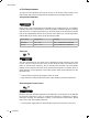
Audience This Installation Guide is for: Network Engineer Network Administrator Conventions Due to the similarity in structure of TL-SL2218/TL-SL2428 Smart Switch, in this Installation Guide we take TL-SL2218 as an example to illustrate Chapter 2 Installation, Chapter 3 Lightning Protection, Chapter 4 Connection and Chapter 5 Login to the Switch. This Guide uses the specific formats to highlight special messages. The following table lists the notice icons that are used throughout this guide.
Contents Chapter 1 1.1 1.2 Chapter 2 2.1 2.2 2.3 2.4 Chapter 3 3.1 3.2 3.3 3.4 Chapter 4 4.1 4.2 4.3 4.4 4.5 Chapter 5 Introduction——————————————— 01 Product Overview.......................................... 01 Appearance................................................... 01 Installation— —————————————— 04 Package Contents.......................................... 04 Safety Precautions......................................... 04 Installation Tools...........................................
Smart Switch CCCCCCCCCC Introduction 1111 Product Overview TL-SL2218 16-Port 10/100Mbps + 2-Port Gigabit Smart Switch and TL-SL2428 24-Port 10/100Mbps + 4-Port Gigabit Smart Switch are both compliant with the IEEE802.3 Ethernet protocols. These switches are equipped with powerful management interface, via which system, port, network, VLAN and priority can be configured. They provide a variety of service features and multiple powerful functions with high security.
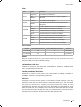
Smart Switch LEDs LED Power System 10/100M 1000M Status Indication On(green1 The switch is powered on Off/ Flashing The switch is powered off or power supply is abnormal Flashing The switch works properly On/Off The switch is powered off or the switch works improperly On A device is linked to the corresponding port Flashing Data is being transmitted or received Green The linked device is running at 100Mbps Yellow The linked device is running at 10Mbps On A device is linked to the cor
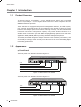
Smart Switch ■■ Rear Panel The rear panel of TL-SL2218 is shown as Figure 1-3. Power Socket Grounding Terminal FFFFFFFFFFFFRear Panel of TL-SL2218 The rear panel of TL-SL2428 is shown as Figure 1-4. Grounding Terminal Power Socket FFFFFFFFFFFFRear Panel of TL-SL2428 Power Socket Connect the female connector of the power cord here, and the male connector to the AC power outlet. Please make sure the voltage of the power supply meets the requirement of the input voltage.
Smart Switch CCCCCCCCCC Installation 2222 Package Contents Make sure that the package contains the following items. If any of the listed items is damaged or missing, please contact your distributor. One Switch One Power Cord One Resource CD Two mounting brackets and the fittings This Installation Guide 2222 Safety Precautions To avoid any device damage and bodily injury caused by improper use, please observe the following rules. ■■ Safety Precautions ■■ Keep the power off during the installation.
Smart Switch ■■ Site Requirements To ensure normal operation and long service life of the device, please install it in an environment that meets the requirements described in the following subsection. Temperature/Humidity ȭ ȭ Please keep a proper temperature and humidity in the equipment room. Too high/low humidity may lead to bad insulation, electricity leakage, mechanical property changes and corrosions.
Smart Switch ■■ ■■ Keep the device far from high-frequency, strong-current devices, such as radio transmitting station. Use electromagnetic shielding when necessary. Lightening Protection Extremely high voltage currents can be produced instantly when lightning occurs and the air in the electric discharge path can be instantly heated up to 20,000℃. As this instant current is strong enough to damage electronic devices, more effective lightning protection measures should be taken.
Smart Switch 2222 Installation Tools ■■ Phillips screwdriver ■■ ESD-preventive wrist wrap ■■ Cables Note: These tools are not provided with our product. If needed, please self purchase them. 2222 Product Installation ■■ Desktop Installation To install the device on the desktop, please follow the steps: 111Set the device on a flat surface strong enough to support the entire weight of the device with all fittings. 222Remove the adhesive backing papers from the rubber feet.
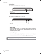
Smart Switch Rackmounting Bracket Screw FFFFFFFFFFF Bracket Installation 333After the brackets are attached to the device, use suitable screws (not provided) to secure the brackets to the rack, as illustrated in the following figure. Rack FFFFFFFFFFF Rack Installation Caution: Please set 5~10cm gaps around the device for air circulation. Please avoid any heavy thing placed on the device.
Smart Switch CCCCCCCCCC Lightning Protection 3333 Cabling Reasonably In the actual network environment, you may need cable outdoors and indoors, and the requirements for cabling outdoors and indoors are different. A reasonable cabling system can decrease the damage of induced lightning to devices. Note: It's not recommended using Ethernet cables outdoors. When cabling outdoors, please use a signal lightning arrester.
Smart Switch ■■ Requirements for Cabling Indoors When cabling indoors, keep a certain distance away from the devices that may cause high-frequency interferences, such as down-conductor cable, powerline, power transformer and electromotor. ■■ ■■ The main cable should be paved in the metal raceway of the access shaft. When cabling, keep the loop area formed by the cable itself as small as possible. Requirements for the distance between Ethernet cable and other pipelines are shown in the table.
Smart Switch 2~5kVA powerline >5kVA powerline Parallel cabling 300 One is in the grounded metal raceway or metal pipe 150 The both are in the grounded metal raceway or metal pipe 80 Parallel cabling 600 One is in the grounded metal raceway or metal pipe 300 The both are in the grounded metal raceway or metal pipe 150 Device Min Distance (m1 Switch case 1.00 Transformer room 2.00 Elevator tower 2.00 Air-conditioner room 2.
Smart Switch Note: The grounding bar and the ground cable are not provided with our product. If needed, please self purchase them. ■■ Connecting to the Ground via the Power Supply If the device is installed in the normal environment, the device can be grounded via the PE (Protecting Earth) cable of the AC power supply as shown in the following figure. FFFFFFFFFFF Connecting to the Ground Note: The figure is to illustrate the application and principle.
Smart Switch Grounding Terminal Equipotential Bonding Cable Ground Cable Grounding Bar FFFFFFFFFFF Equipotential Bonding When equipotential bonding, please note that the cable should be copper wrapped 2 Kelly with its area being 6mm at least. The shorter cable the better, and use a grounding bar to establish an equipotential bonding point. Note: The equipotential bonding cable is not provided with our product. If needed, please self purchase it.
Smart Switch ■■ ■■ The port rate of the signal lightning arrester should match the rate of the desired port on the device. If it is not matched, this signal lighting arrester will not work. Purchase a standard lightning arrester. Install signal lightning arrester near the protected device and connect it to the ground via a shorter ground cable.
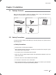
Smart Switch CCCCCCCCCC Connection 4444 Ethernet Port Please connect the Ethernet ports of the switch to the network devices by RJ45 cable as the following figure shown. RJ45 Port RJ45 Cable FFFFFFFFFFF Connecting the RJ45 Port 4444 SFP Port Connect the SFP port to a SFP module. For the switch, if an SFP transceiver (purchased separately) is installed in a slot and has a valid link on the port, the associated RJ45 port will be disabled and cannot be used.
Smart Switch 4444 Verify Installation After completing the installation, please verify the following items: ■■ There are 5~10cm of clearance around the sides of the device for ventilation and the air flow is adequate. ■■ The voltage of the power supply meets the requirement of the input voltage of the device. ■■ The power socket, device and rack are well grounded. ■■ The device is correctly connected to other network devices.
Smart Switch ChaCter 4 Login to the Switch 1. To access the GUI of the switch, open a web browser and type the default management address http://192.168.0.1 in the address field of the browser, then click the GO button or press the Enter key. Figure 5-1 Web Browser Note: To log on to the GUI of the switch, the IP address of your PC should be set in the same subnet addresses of the switch. The IP address is 192.168.0.x ("x" is any number from 2 to 2541, Subnet Mask is 255.255.255.0.
Smart Switch Appendix A Troubleshooting QQQQ What could I do if I forgot the username and password of the switch? With the switch powered on, press the Reset button on the front panel for five seconds to reset the system to its factory default settings, and the default login user name and password are both admin. QQQQ Why does the Power LED work abnormally? The Power LED should be lit up when the power system works normally.
Smart Switch Appendix B Hardware Specifications Item Content Standards and Protocol IEEE 802.3 10Base-T IEEE 802.3u 100Base-TX/100Base-FX IEEE 802.3ab 1000Base-T IEEE 802.3z 1000Base-X IEEE 802.3x Flow Control Transmission Medium 10Base-T: UTP/STP of Cat. 3 or above 100Base-TX: UTP/STP of Cat. 5 or above 1000Base-T: 4-pair UTP (≤100m1 of Cat. 5, Cat. 5e, and Cat.
Smart Switch Appendix C Technical Support ■■ ■■ For more help, please go to: http://www.tp-link.com/en/support/faq To download the latest Firmware, Driver, Utility and User Guide, please go to: http://www.tp-link.com/en/support/download ■■ For all other technical support, please contact us by using the following details: Global Tel: +86 755 2650 4400 E-mail: support@tp-link.com Service time: 24hrs, 7 days a week Australia/New Zealand Tel: AU 1300 87 5465 NZ 0800 87 5465 E-mail: support.au@tp-link.
Smart Switch 21 Singapore Tel: +65 6284 0493 E-mail: support.sg@tp-link.com Service time: 24hrs, 7 days a week Switzerland Tel: +41 (01 848 800 998 (German Service1 E-mail: support.ch@tp-link.com Fee: 4-8 Rp/min, depending on rate of different time Service time: Monday to Friday, 9:00 to 12:30 and 13:30 to 17:30. GMT+ 1 or GMT+ 2 (Daylight Saving Time1 Turkey Tel: 444 1925 (Turkish Service1 E-mail: support.tr@tp-link.
Website: http://www.tp-link.com E-mail: smb@tp-link.com.cn 7106504093 Rev: 1.1.