TL-SL2210/TL-SL2218/TL-SL2428/TL-SL2452 Smart Switch REV1.2.
COPYRIGHT & TRADEMARKS Specifications are subject to change without notice. is a registered trademark of TP-LINK TECHNOLOGIES CO., LTD. Other brands and product names are trademarks or registered trademarks of their respective holders. No part of the specifications may be reproduced in any form or by any means or used to make any derivative such as translation, transformation, or adaptation without permission from TP-LINK TECHNOLOGIES CO., LTD. Copyright © 2014 TP-LINK TECHNOLOGIES CO., LTD.
Safety Information When product has power button, the power button is one of the way to shut off the product; When there is no power button, the only way to completely shut off power is to disconnect the product or the power adapter from the power source. Don’t disassemble the product, or make repairs yourself. You run the risk of electric shock and voiding the limited warranty. If you need service, please contact us. Avoid water and wet locations.
CONTENTS Package Contents ..........................................................................................................................1 Chapter 1 About this Guide...........................................................................................................2 1.1 Intended Readers .........................................................................................................2 1.2 Conventions ................................................................................
.2 5.3 5.4 5.5 5.1.1 Port Config .......................................................................................................30 5.1.2 Port Mirror ........................................................................................................31 5.1.3 Port Security ....................................................................................................33 5.1.4 Port Isolation ............................................................................................
8.2 8.3 8.4 8.1.1 Snooping Config ..............................................................................................83 8.1.2 Port Config .......................................................................................................84 8.1.3 VLAN Config ....................................................................................................85 8.1.4 Multicast VLAN ................................................................................................
10.4 10.3.2 Port Binding ................................................................................................... 118 10.3.3 VLAN Binding................................................................................................. 118 Application Example for ACL .................................................................................... 119 Chapter 11 SNMP.......................................................................................................................
Package Contents The following items should be found in your box: One TL-SL2210/TL-SL2218/TL-SL2428/TL-SL2452 Smart Switch One power cord Two mounting brackets and other fittings Installation Guide Resource CD for TL-SL2210/TL-SL2218/TL-SL2428/TL-SL2452 switch, including: This User Guide Other Helpful Information Note: Make sure that the package contains the above items. If any of the listed items are damaged or missing, please contact your distributor.
Chapter 1 About this Guide This User Guide contains information for setup and management of TL-SL2210/TL-SL2218 /TL-SL2428/TL-SL2452 Smart Switch. Please read this guide carefully before operation. 1.1 Intended Readers This Guide is intended for network managers familiar with IT concepts and network terminologies. 1.2 Conventions In this Guide the following conventions are used: The four devices of TL-SL2210, TL-SL2218, TL-SL2428 and TL-SL2452 are sharing this User Guide.
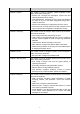
Chapter Introduction Chapter 4 System This module is used to configure system properties of the switch. Here mainly introduces: System Info: Configure the description, system time and network parameters of the switch. User Management: Configure the user name and password for users to log on to the Web management page with a certain access level. System Tools: Manage the configuration file of the switch.
Chapter Introduction Chapter 9 QoS This module is used to configure QoS function to provide different quality of service for various network applications and requirements. Here mainly introduces: DiffServ: Configure priorities, port priority, 802.1P priority and DSCP priority. Bandwidth Control: Configure rate limit feature to control the traffic rate on each port; configure storm control feature to filter broadcast, multicast and UL frame in the network.
Chapter 2 Introduction Thanks for choosing the TL-SL2210/TL-SL2218/TL-SL2428/TL-SL2452 Smart Switch! 2.1 Overview of the Switch Designed for workgroups and departments, TL-SL2210/TL-SL2218/TL-SL2428/TL-SL2452 from TP-LINK provides wire-speed performance and full set of layer 2 management features. It provides a variety of service features and multiple powerful functions with high security.
The front panel of TL-SL2218 is shown as Figure 2-2. Figure 2-2 Front Panel of TL-SL2218 The front panel of TL-SL2428 is shown as Figure 2-3. Figure 2-3 Front Panel of TL-SL2428 The front panel of TL-SL2452 is show as Figure 2-4. Figure 2-4 Front Panel of TL-SL2452 The following parts are located on the front panel of the switch: Reset: Press this button for five seconds or above to reset the software setting back to factory default setting.
default, the Speed and Duplex mode of SFP port is 1000MFD. For TL-SL2210/TL-SL2452, the SFP port can only be used with a gigabit module. LEDs Name Power Status On(green) Flashing/Off Flashing System On/Off On Indication The switch is powered on. The switch is powered off or power supply is abnormal. The switch is working normally. The switch is powered off or the switch is working abnormally. A device is linked to the corresponding port.
The rear panel of TL-SL2428 is shown as the following figure. Figure 2-7 Rear Panel of TL-SL2428 The rear panel of TL-SL2452 is shown as the following figure. Figure 2-8 Rear Panel of TL-SL2452 Grounding Terminal: TL-SL2210/TL-SL2218/TL-SL2428/TL-SL2452 already comes with Lightning Protection Mechanism. You can also ground the switch through the PE (Protecting Earth) cable of AC cord or with Ground Cable.
Chapter 3 Login to the Switch 3.1 Login 1) To access the configuration utility, open a web-browser and type in the default address http://192.168.0.1 in the address field of the browser, then press the Enter key. Figure 3-1 Web-browser Tips: To log in to the switch, the IP address of your PC should be set in the same subnet addresses of the switch. The IP address is 192.168.0.x ("x" is any number from 2 to 254), Subnet Mask is 255.255.255.0.
Figure 3-3 Main Setup-Menu Note: Clicking Apply can only make the new configurations effective before the switch is rebooted. If you want to keep the configurations effective even the switch is rebooted, please click Save Config. You are suggested to click Save Config before cutting off the power or rebooting the switch to avoid losing the new configurations.
Chapter 4 System The System module is mainly for system configuration of the switch, including four submenus: System Info, User Manage, System Tools and Access Security. 4.1 System Info The System Info, mainly for basic properties configuration, can be implemented on System Summary, Device Description, System Time, Daylight Saving Time and System IP pages. 4.1.1 System Summary On this page you can view the port connection status and the system information.
Indicates the 1000Mbps port is at the speed of 1000Mbps. Indicates the 1000Mbps port is at the speed of 10Mbps or 100Mbps. Indicates the SFP port is not connected to a device. Indicates the SFP port is at the speed of 1000Mbps. Indicates the SFP port is at the speed of 100Mbps. When the cursor moves on the port, the detailed information of the port will be displayed. Figure 4-2 Port Information Port Info Port: Displays the port number of the switch. Type: Displays the type of the port.
Bandwidth Utilization Rx: Select Rx to display the bandwidth utilization of receiving packets on this port. Tx: Select Tx to display the bandwidth utilization of sending packets on this port. 4.1.2 Device Description On this page you can configure the description of the switch, including device name, device location and system contact. Choose the menu System→System Info→Device Description to load the following page.
Choose the menu System→System Info→System Time to load the following page. Figure 4-5 System Time The following entries are displayed on this screen: Time Info Current System Date: Displays the current date and time of the switch. Current Time Source: Displays the current time source of the switch. Time Config Manual: When this option is selected, you can set the date and time manually.
Figure 4-6 Daylight Saving Time The following entries are displayed on this screen: DST Config DST Status: Enable or disable the DST. Predefined Mode: Select a predefined DST configuration. Recurring Mode: Specify the DST configuration configuration is recurring in use. Date Mode: USA: Second Sunday in March, 02:00 ~ First Sunday in November, 02:00. Australia: First Sunday in October, 02:00 ~ First Sunday in April, 03:00.
4.1.5 System IP Each device in the network possesses a unique IP address. You can log on to the Web management page to operate the switch using this IP address. The switch supports three modes to obtain an IP address: Static IP, DHCP and BOOTP. The IP address obtained using a new mode will replace the original IP address. On this page you can configure the system IP of the switch. Choose the menu System→System Info→System IP to load the following page.
2. The switch only possesses an IP address. The IP address configured will replace the original IP address. 3. If the switch gets the IP address from DHCP server, you can see the configuration of the switch in the DHCP server; if DHCP option is selected but no DHCP server exists in the network, the switch will keep obtaining IP address from DHCP server until success. 4.
Choose the menu System→User Management→User Config to load the following page. Figure 4-9 User Config The following entries are displayed on this screen: User Info User Name: Create a name for users’ login. Access Level: Select the access level to login. User Status: Select Enable/Disable the user configuration. Password: Type a password for users’ login. Confirm Password: Retype the password. Password Mode: Select the password display mode from the pull-down list.
Operation: Click the Edit button of the desired entry, and you can edit the corresponding user information. After modifying the settings, please click the Modify button to make the modification effective. Access level and user status of the current user information can’t be modified. Note: Password Display Mode is not supported by TL-SL2210. 4.
Choose the menu System→System Tools→Config Backup to load the following page. Figure 4-11 Config Backup The following entries are displayed on this screen: Config Backup Backup Config: Click the Backup Config button to save the current configuration as a file to your computer. You are suggested to take this measure before upgrading. Note: It will take a few minutes to backup the configuration. Please wait without any operation. 4.3.
4.3.4 System Reboot On this page you can reboot the switch and return to the login page. Please save the current configuration before rebooting to avoid losing the configuration unsaved Choose the menu System→System Tools→System Reboot to load the following page. Figure 4-13 System Reboot Note: To avoid damage, please don't turn off the device while rebooting. 4.3.5 System Reset On this page you can reset the switch to the default. All the settings will be cleared after the switch is reset.
Figure 4-15 Access Control The following entries are displayed on this screen: Access Control Config Control Mode: Select the control mode for users to log on to the Web management page. Disable:Disable the access control function. IP-based: Select this option to limit the IP-range of the users for login. MAC-based: Select this option to limit the MAC address of the users for login. Port-based: Select this option to limit the ports for login.
Session Config Session Timeout: If you do nothing with the Web management page within the timeout time, the system will log out automatically. If you want to reconfigure, please login again. Access User Number Number Control: Select Enable/Disable the Number Control function. Admin Number: Enter the maximum number of the users logging on to the Web management page as Admin. Guest Number: Enter the maximum number of the users logging on to the Web management page as Guest. 4.4.
Choose the menu System→Access Security→SSL Config to load the following page. Figure 4-16 SSL Config The following entries are displayed on this screen: Global Config SSL: Certificate Download Certificate File: Select Enable/Disable the SSL function on the switch. Select the desired certificate to download to the switch. The certificate must be BASE64 encoded. Key Download Key File: Select the desired SSL key to download to the switch. The key must be BASE64 encoded. Note: 1.
an insecure network environment. It can encrypt all the transmission data and prevent the information in a remote management being leaked. Comprising server and client, SSH has two versions, V1 and V2 which are not compatible with each other. In the communication, SSH server and client can auto-negotiate the SSH version and the encryption algorithm.
Key Download Key Type: Select the type of SSH key to download. The switch supports three types: SSH-1 RSA, SSH-2 RSA and SSH-2 DSA. Key File: Select the desired key file to download. Download: Click the Download button to down the desired key file to the switch. Note: 1. Please ensure the key length of the downloaded file is in the range of 256 to 3072 bits. 2. After the key file is downloaded, the user’s original key of the same type will be replaced.
Application Example 2 for SSH: Network Requirements 1. Log on to the switch via password authentication using SSH and the SSH function is enabled on the switch. 2. PuTTY client software is recommended. Configuration Procedure 1. Select the key type and key length, and generate SSH key. Note: 1. The key length is in the range of 256 to 3072 bits. 2. During the key generation, randomly moving the mouse quickly can accelerate the key generation. 3.
2. On the Web management page of the switch, download the public key file saved in the computer to the switch. Note: 1. The key type should accord with the type of the key file. 2. The SSH key downloading can not be interrupted. 3. Download the private key file to SSH client software.
3. After the public key and private key are downloaded, please log on to the interface of PuTTY and enter the IP address for login. After successful authentication, please enter the login user name. If you log on to the switch without entering password, it indicates that the key has been successfully downloaded.
Chapter 5 Switching Switching module is used to configure the basic functions of the switch, including four submenus: Port, LAG, Traffic Monitor and MAC Address. 5.1 Port The Port function, allowing you to configure the basic features for the port, is implemented on the Port Config, Port Mirror, Port Security, Port Isolation and Loopback Detection pages. 5.1.1 Port Config On this page, you can configure the basic parameters for the ports.
Description: Give a description to the port for identification. Status: Allows you to Enable/Disable the port. When Enable is selected, the port can forward the packets normally. Speed and Duplex: Select the Speed and Duplex mode for the port. The device connected to the switch should be in the same Speed and Duplex mode with the switch. When “Auto” is selected, the Speed and Duplex mode will be determined by auto-negotiation. For the SFP port, this switch does not support auto-negotiation.
The following entries are displayed on this screen. Mirror Group List Group: Displays the mirror group number. Mirroring: Displays the mirroring port number. Mode: Displays the mirror mode. The value will be "Ingress" or "Egress". Mirrored Port: Displays the mirrored ports. Operation: Click Edit to configure the mirror group. Click Edit to display the following figure.
Mirrored Port Port Select: Click the Select button to quick-select the corresponding port based on the port number you entered. Select: Select the desired port as a mirrored port. It is multi-optional. Port: Displays the port number. Ingress: Select Enable/Disable the Ingress feature. When the Ingress is enabled, the incoming packets received by the mirrored port will be copied to the mirroring port. Egress: Select Enable/Disable the Egress feature.
Figure 5-4 Port Security The following entries are displayed on this screen: Port Security Select: Select the desired port for Port Security configuration. It is multi-optional. Port: Displays the port number. Max Learned MAC: Specify the maximum number of MAC addresses that can be learned on the port. Learned Num: Displays the number of MAC addresses that have been learned on the port. Learn Mode: Select the Learn Mode for the port.
5.1.4 Port Isolation Port Isolation provides a method of restricting traffic flow to improve the network security by forbidding the port to forward packets to the ports that are not on its forward portlist. Choose the menu Switching→Port→Port Isolation to load the following page. Figure 5-5 Port Isolation The following entries are displayed on this screen: Port Isolation Config Port: Select the port number to set its forwardlist. Forward Portlist: Select the port that to be forwarded to.
5.1.5 Loopback Detection With loopback detection feature enabled, the switch can detect loops using loopback detection packets. When a loop is detected, the switch will display an alert or further block the corresponding port according to the port configuration. Choose the menu Switching→Port→Loopback Detection to load the following page.
Port Config Port Select: Click the Select button to quick-select the corresponding port based on the port number you entered. Select: Select the desired port for loopback detection configuration. It is multi-optional. Port: Displays the port number. Status: Enable or disable loopback detection function for the port. Operation Mode: Select the mode how the switch processes the detected loops. Recovery Mode: Alert: When a loop is detected, displays an alert.
Tips: 1. Calculate the bandwidth for a LAG: If a LAG consists of the four ports in the speed of 1000Mbps Full Duplex, the whole bandwidth of the LAG is up to 8000Mbps (2000Mbps * 4) because the bandwidth of each member port is 2000Mbps counting the up-linked speed of 1000Mbps and the down-linked speed of 1000Mbps. 2. The traffic load of the LAG will be balanced among the ports according to the Aggregate Arithmetic.
Operation: Allows you to view or modify the information for each LAG. Edit: Click to modify the settings of the LAG. Detail: Click to get the information of the LAG. Click the Detail button for the detailed information of your selected LAG. Figure 5-8 Detailed Information 5.2.2 Static LAG On this page, you can manually configure the LAG. Choose the menu Switching→LAG→Static LAG to load the following page.
The following entries are displayed on this screen: LAG Config Group Number: Select a Group Number for the LAG. Description: Displays the description of the LAG. Member Port Member Port: Select the port as the LAG member. Clearing all the ports of the LAG will delete this LAG. Tips: 1. The LAG can be deleted by clearing its all member ports. 2. A port can only be added to a LAG. If a port is the member of a LAG, the port number will be displayed in gray and can not be selected. 5.2.
Figure 5-10 LACP Config The following entries are displayed on this screen: Global Config System Priority: Specify the system priority for the switch. The system priority and MAC address constitute the system identification (ID). A lower system priority value indicates a higher system priority.
Status: Enable/Disable the LACP feature for your selected port. LAG: Displays the LAG number which the port belongs to. 5.3 Traffic Monitor The Traffic Monitor function, monitoring the traffic of each port, is implemented on the Traffic Summary and Traffic Statistics pages. 5.3.1 Traffic Summary Traffic Summary screen displays the traffic information of each port, which facilitates you to monitor the traffic and analyze the network abnormity.
Port: Displays the port number. Packets Rx: Displays the number of packets received on the port. The error packets are not counted in. Packets Tx: Displays the number of packets transmitted on the port. Octets Rx: Displays the number of octets received on the port. The error octets are counted in. Octets Tx: Displays the number of octets transmitted on the port. Statistics: Click the Statistics button to view the detailed traffic statistics of the port. 5.3.
Statistics Port: Enter a port number and click the Select button to view the traffic statistics of the corresponding port. Received: Displays the details of the packets received on the port. Sent: Displays the details of the packets transmitted on the port. Broadcast: Displays the number of good broadcast packets received or transmitted on the port. The error frames are not counted in. Multicast: Displays the number of good multicast packets received or transmitted on the port.
Type Configuration Way Aging out Being kept after Relationship between the reboot bound MAC address and (if the configuration the port is saved) Static Manually Address Table configuring No Yes The bound MAC address can not be learned by the other ports in the same VLAN. Dynamic Automatically Address Table learning Yes No The bound MAC address can be learned by the other ports in the same VLAN.
Static: This option allows the address table to display the static address entries only. Dynamic: This option allows the address table to display the dynamic address entries only. Filtering: This option allows the address table to display the filtering address entries only. Address Table MAC Address: Displays the MAC address learned by the switch. VLAN ID: Displays the corresponding VLAN ID of the MAC address. Port: Displays the corresponding Port number of the MAC address.
VLAN ID: Enter the corresponding VLAN ID of the MAC address. Port: Select a port from the pull-down list to be bound. Search Option Search Option: Select a Search Option from the pull-down list and click the Search button to find your desired entry in the Static Address Table. MAC: Enter the MAC address of your desired entry. VLAN ID: Enter the VLAN ID number of your desired entry. Port: Enter the Port number of your desired entry.
Figure 5-15 Dynamic Address The following entries are displayed on this screen: Aging Config Auto Aging: Allows you to Enable/Disable the Auto Aging feature. Aging Time: Enter the Aging Time for the dynamic address. Search Option Search Option: Select a Search Option from the pull-down list and click the Search button to find your desired entry in the Dynamic Address Table. MAC: Enter the MAC address of your desired entry. VLAN ID: Enter the VLAN ID number of your desired entry.
Bind: Click the Bind button to bind the MAC address of your selected entry to the corresponding port statically. Tips: Setting aging time properly helps implement effective MAC address aging. The aging time that is too long or too short results decreases the performance of the switch. If the aging time is too long, excessive invalid MAC address entries maintained by the switch may fill up the MAC address table. This prevents the MAC address table from updating with network changes in time.
VLAN ID: Enter the VLAN ID number of your desired entry. Filtering Address Table Select: Select the entry to delete the corresponding filtering address. It is multi-optional. MAC Address: Displays the filtering MAC address. VLAN ID: Displays the corresponding VLAN ID. Port: Here the symbol “__” indicates no specified port. Type: Displays the Type of the MAC address. Aging Status: Displays the Aging Status of the MAC address.
Figure 5-17 Network diagram of DHCP For different DHCP clients, DHCP server provides three IP address assigning methods: (1) (2) (3) Manually assign the IP address: Allows the administrator to bind the static IP address to a specific client (e.g.: WWW Server) via the DHCP server. Automatically assign the IP address: DHCP server assigns the IP address without an expiry time limitation to the clients. Dynamically assign the IP address: DHCP server assigns the IP address with an expiry time.
packet and broadcast the DHCP-REQUEST packet which includes the assigned IP address of the DHCP-OFFER packet. (4) DHCP-ACK Stage: Since the DHCP-REQUEST packet is broadcasted, all DHCP servers on the network segment can receive it. However, only the requested server processes the request. If the DHCP server acknowledges assigning this IP address to the client, it will send the DHCP-ACK packet back to the client.
Figure 5-20 DHCP Filtering The following entries are displayed on this screen: DHCP Filtering DHCP Filtering: Enable/Disable the DHCP Filtering function globally. Trusted Port Here you can select the desired port(s) to be Trusted Port(s). Only the Trusted Port(s) can receive DHCP packets from DHCP Servers. Click All button to select all ports. Click Clear button to select none.
Chapter 6 VLAN The traditional Ethernet is a data network communication technology based on CSMA/CD (Carrier Sense Multiple Access/Collision Detect) via shared communication medium. Through the traditional Ethernet, the overfull hosts in LAN will result in serious collision, flooding broadcasts, poor performance or even breakdown of the Internet.
6.1 802.1Q VLAN VLAN tags in the packets are necessary for the switch to identify packets of different VLANs. The switch works at the data link layer in OSI model and it can identify the data link layer encapsulation of the packet only, so you can add the VLAN tag field into the data link layer encapsulation for identification. In 1999, IEEE issues the IEEE 802.1Q protocol to standardize VLAN implementation, defining the structure of VLAN-tagged packets. IEEE 802.
ingress port belongs to, this packet will be dropped. When the VLAN-tagged packets are forwarded by the Tagged port, its VLAN tag will not be changed. PVID PVID (Port VLAN ID) is the default VID of the port. When the switch receives an un-VLAN-tagged packet, it will add a VLAN tag to the packet according to the PVID of its received port and forward the packets.
Figure 6-3 VLAN Table To ensure the normal communication of the factory switch, the default VLAN of all ports is set to VLAN1. VLAN1 cannot be modified or deleted. The following entries are displayed on this screen: VLAN Create VLAN ID: Enter the VLAN ID you want to create. It ranges from 2 to 4094. Name: Give a name to the VLAN for identification. VLAN Table VLAN ID Select: Click the Select button to quick-select the corresponding VLAN based on the VLAN ID you entered.
Untagged: The port will be an untagged member of the specific VLAN if you select it. Tagged: The port will be an tagged member of the specific VLAN if you select it. NotMember: The port will not be a member of the specific VLAN if you select it. PVID: Here you can change the PVID of the specific port. LAG: Displays the LAG to which the port belongs to. 6.2 Application Example for 802.
Configuration Procedure Configure Switch A Step Operation Description 1 Configure the Link Type of the ports Required. On VLAN→802.1Q VLAN→VLAN Config page, configure the link type of Port 2, Port 3 and Port 4 as Untagged, Tagged and Untagged respectively 2 Create VLAN10 Required. On VLAN→802.1Q VLAN→VLAN Config page, create a VLAN with its VLAN ID as 10, owning Port 2 and Port 3. 3 Create VLAN20 Required. On VLAN→802.
Chapter 7 Spanning Tree STP (Spanning Tree Protocol), subject to IEEE 802.1D standard, is to disbranch a ring network in the Data Link layer in a local network. Devices running STP discover loops in the network and block ports by exchanging information, in that way, a ring network can be disbranched to form a tree-topological ring-free network to prevent packets from being duplicated and forwarded endlessly in the network. BPDU (Bridge Protocol Data Unit) is the protocol data that STP and RSTP use.
Figure 7-1 Basic STP diagram STP Timers Hello Time: Hello Time ranges from 1 to 10 seconds. It specifies the interval to send BPDU packets. It is used to test the links. Max. Age: Max. Age ranges from 6 to 40 seconds. It specifies the maximum time the switch can wait without receiving a BPDU before attempting to reconfigure. Forward Delay: Forward Delay ranges from 4 to 30 seconds. It specifies the time for the port to transit its state after the network topology is changed.
Comparing BPDUs Each switch sends out configuration BPDUs and receives a configuration BPDU on one of its ports from another switch. The following table shows the comparing operations. Step Operation 1 If the priority of the BPDU received on the port is lower than that of the BPDU if of the port itself, the switch discards the BPDU and does not change the BPDU of the port.
The condition for the root port to transit its port state rapidly: The old root port of the switch stops forwarding data and the designated port of the upstream switch begins to forward data. The condition for the designated port to transit its port state rapidly: The designated port is an edge port or connecting to a point-to-point link.
The following figure shows the network diagram in MSTP. Figure 7-2 Basic MSTP diagram MSTP MSTP divides a network into several MST regions. The CST is generated between these MST regions, and multiple spanning trees can be generated in each MST region. Each spanning tree is called an instance. As well as STP, MSTP uses BPDUs to generate spanning tree. The only difference is that the BPDU for MSTP carries the MSTP configuration information on the switches.
The following diagram shows the different port roles. Figure 7-3 Port roles The Spanning Tree module is mainly for spanning tree configuration of the switch, including four submenus: STP Config, Port Config, MSTP Instance and STP Security. 7.1 STP Config The STP Config function, for global configuration of spanning trees on the switch, can be implemented on STP Config and STP Summary pages. 7.1.
The following entries are displayed on this screen: Global Config STP: Select Enable/Disable STP function globally on the switch. Version: Select the desired STP version on the switch. STP: Spanning Tree Protocol. RSTP: Rapid Spanning Tree Protocol. MSTP: Multiple Spanning Tree Protocol. Parameters Config CIST Priority: Enter a value from 0 to 61440 to specify the priority of the switch for comparison in the CIST. CIST priority is an important criterion on determining the root bridge.
7.1.2 STP Summary On this page you can view the related parameters for Spanning Tree function. Choose the menu Spanning Tree→STP Config→STP Summary to load the following page. Figure 7-5 STP Summary 7.2 Port Config On this page you can configure the parameters of the ports for CIST. Choose the menu Spanning Tree→Port Config to load the following page.
Figure 7-6 Port Config The following entries are displayed on this screen: Port Config Port Select: Click the Select button to quick-select the corresponding port based on the port number you entered. Select: Select the desired port for STP configuration. It is multi-optional. Port: Displays the port number of the switch. Status: Select Enable /Disable STP function for the desired port. Priority: Enter a value from 0 to 240 divisible by 16.
Port Role: Displays the role of the port played in the STP Instance. Port Status: Displays the working status of the port. LAG: Root Port: Indicates the port that has the lowest path cost from this bridge to the Root Bridge and forwards packets to the root. Designated Port: Indicates the port that forwards packets to a downstream network segment or switch. Master Port: Indicates the port that connects an MST region to the common root.
Figure 7-7 Region Config The following entries are displayed on this screen: Region Config Region Name: Create a name for MST region identification using up to 32 characters. Revision: Enter the revision from 0 to 65535 for MST region identification. 7.3.2 Instance Config Instance Configuration, a property of MST region, is used to describe the VLAN to Instance mapping configuration. You can assign VLAN to different instances appropriate to your needs.
The following entries are displayed on this screen: Instance Table Instance ID Select: Click the Select button to quick-select the corresponding Instance ID based on the ID number you entered. Select: Select the desired Instance ID for configuration. It is multi-optional. Instance: Displays Instance ID of the switch. Status: Displays the status of the instance. Priority: Enter the priority of the switch in the instance.
Choose the menu Spanning Tree→MSTP Instance→Instance Port Config to load the following page. Figure 7-9 Instance Port Config The following entries are displayed on this screen: Port Config Instance ID: Select the desired instance ID for its port configuration. Port Select: Click the Select button to quick-select the corresponding port based on the port number you entered. Select: Select the desired port to specify its priority and path cost. It is multi-optional.
Global configuration Procedure for Spanning Tree function: Step Operation Description 1 Make clear roles the switches play in spanning tree instances: root bridge or designated bridge Preparation. 2 Globally configure parameters MSTP Required. Enable Spanning Tree function on the switch and configure MSTP parameters on Spanning Tree→STP Config→STP Config page. 3 Configure MSTP parameters for ports Required. Configure MSTP parameters for ports on Spanning Tree→Port Config→Port Config page.
its position and network topology jitter to occur. In this case, flows that should travel along high-speed links may lead to low-speed links, and network congestion may occur. To avoid this, MSTP provides root protect function. Ports with this function enabled can only be set as designated ports in all spanning tree instances. When a port of this type receives BDPU packets with higher priority, it transits its state to blocking state and stops forwarding packets (as if it is disconnected from the link).
Figure 7-10 Port Protect The following entries are displayed on this screen: Port Protect Port Select: Click the Select button to quick-select the corresponding port based on the port number you entered. Select: Select the desired port for port protect configuration. It is multi-optional. Port: Displays the port number of the switch. Loop Protect: Loop Protect is to prevent the loops in the network brought by recalculating STP because of link failures and network congestions.
Choose the menu Spanning Tree→STP Security→TC Protect to load the following page. Figure 7-11 TC Protect The following entries are displayed on this screen: TC Protect TC Threshold: Enter a number from 1 to 100. It is the maximum number of the TC-BPDUs received by the switch in a TC Protect Cycle. The default value is 20. TC Protect Cycle: Enter a value from 1 to 10 to specify the TC Protect Cycle. The default value is 5. 7.
Configuration Procedure Configure Switch A: Step Operation Description 1 Configure ports On VLAN→802.1Q VLAN page, configure the link type of the related ports as Tagged, and add the ports to VLAN101-VLAN106. The detailed instructions can be found in the section 802.1Q VLAN. 2 Enable STP function On Spanning Tree→STP Config→STP Config page, enable STP function and select MSTP version. On Spanning Tree→STP Config→Port Config page, enable MSTP function for the port.
Configure Switch C: Step Operation Description 1 Configure ports On VLAN→802.1Q VLAN page, configure the link type of the related ports as Tagged, and add the ports to VLAN101-VLAN106. The detailed instructions can be found in the section 802.1Q VLAN. 2 Enable STP function On Spanning Tree→STP Config→STP Config page, enable STP function and select MSTP version. On Spanning Tree→STP Config→Port Config page, enable MSTP function for the port.
The configuration procedure for switch E and F is the same with that for switch D. The topology diagram of the two instances after the topology is stable For Instance 1 (VLAN101, 103 and 105), the red paths in the following figure are connected links; the gray paths are the blocked links. For Instance 2 (VLAN102, 104 and 106), the blue paths in the following figure are connected links; the gray paths are the blocked links.
Chapter 8 Multicast Multicast Overview In the network, packets are sent in three modes: unicast, broadcast and multicast. In unicast, the source server sends separate copy information to each receiver. When a large number of users require this information, the server must send many pieces of information with the same content to the users. Therefore, large bandwidth will be occupied. In broadcast, the system transmits information to all users in a network.
Multicast Address 1. Multicast IP Address: As specified by IANA (Internet Assigned Numbers Authority), Class D IP addresses are used as destination addresses of multicast packets. The multicast IP addresses range from 224.0.0.0~239.255.255.255. The following table displays the range and description of several special multicast IP addresses. Multicast IP address range Description 224.0.0.0~224.0.0.255 Reserved multicast addresses for routing protocols and other network protocols 224.0.1.0~224.0.1.
should be a group port list, so the switch will duplicate this multicast data and deliver each port one copy. The general format of the multicast address table is described as Figure 8-3 below. VLAN ID Multicast IP Port Figure 8-3 Multicast Address Table IGMP Snooping In the network, the hosts apply to the near router for joining (leaving) a multicast group by sending IGMP (Internet Group Management Protocol) messages.
When receiving IGMP report message, the switch will send the report message via the router port in the VLAN as well as analyze the message to get the address of the multicast group the host applies for joining. The receiving port will be processed: if the receiving port is a new member port, it will be added to the multicast address table with its member port time specified; if the receiving port is already a member port, its member port time will be directly reset. 3.
Figure 8-4 Basic Config The following entries are displayed on this screen: Global Config IGMP Snooping: Select Enable/Disable IGMP Snooping function globally on the switch. Unknown Multicast: Select the operation for the switch to process unknown multicast, Forward or Discard. IGMP Snooping Status Description: Displays IGMP Snooping status. Member: Displays the member of the corresponding status. 8.1.2 Port Config On this page you can configure the IGMP feature for ports of the switch.
Choose the menu Multicast→IGMP Snooping→Port Config to load the following page. Figure 8-5 Port Config The following entries are displayed on this screen: Port Config Port Select: Click the Select button to quick-select the corresponding port based on the port number you entered. Select: Select the desired port for IGMP Snooping feature configuration. It is multi-optional. Port: Displays the port of the switch. IGMP Snooping: Select Enable/Disable IGMP Snooping for the desired port.
Figure 8-6 VLAN Config The following entries are displayed on this screen: VLAN Config VLAN ID: Enter the VLAN ID to enable IGMP Snooping for the desired VLAN. Router Port Time: Specify the aging time of the router port. Within this time, if the switch doesn’t receive IGMP query message from the router port, it will consider this port is not a router port any more. Member Port Time: Specify the aging time of the member port.
Router Port: Displays the router port of the VLAN. Note: The settings here will be invalid when multicast VLAN is enabled Configuration procedure: Step Operation 1 Enable function Snooping Required. Enable IGMP Snooping globally on the switch and for the port on Multicast→IGMP Snooping→Snooping Config and Port Config page. 2 Configure the multicast parameters for VLANs Optional. Configure the multicast parameters for VLANs on Multicast→IGMP Snooping→VLAN Config page.
The following entries are displayed on this screen: Multicast VLAN Multicast VLAN: Select Enable/Disable Multicast VLAN feature. VLAN ID: Enter the VLAN ID of the multicast VLAN. Router Port Time: Specify the aging time of the router port. Within this time, if the switch doesn’t receive IGMP query message from the router port, it will consider this port is not a router port any more. Member Port Time: Specify the aging time of the member port.
Application Example for Multicast VLAN: Network Requirements Multicast source sends multicast streams via the router, and the streams are transmitted to user A and user B through the switch. Router: Its WAN port is connected to the multicast source; its LAN port is connected to the switch. The multicast packets are transmitted in VLAN3.
Step Operation Description 3 Enable IGMP Snooping function Enable IGMP Snooping function globally on Multicast→IGMP Snooping→Snooping Config page. Enable IGMP Snooping function for port 3, port 4 and port 5 on Multicast→IGMP Snooping→Port Config page. 4 Enable VLAN Multicast Enable Multicast VLAN, configure the VLAN ID of a multicast VLAN as 3 and keep the other parameters as default on Multicast→IGMP Snooping→Multicast VLAN page.
Multicast IP Table Multicast IP Displays multicast IP address. VLAN ID: Displays the VLAN ID of the multicast group. Forward Port Displays the forward port of the multicast group. Type: Displays the type of the multicast IP. Note: If the configuration on VLAN Config page and multicast VLAN page is changed, the switch will clear up the dynamic multicast addresses in multicast address table and learn new addresses. 8.2.
Search Option Search Option: Select the rules for displaying multicast IP table to find the desired entries quickly. All: Displays all static multicast IP entries. Multicast IP: Enter the multicast IP address the desired entry must carry. VLAN ID: Enter the VLAN ID the desired entry must carry. Port: Enter the port number the desired entry must carry. Static Multicast IP Table Select: Select the desired entry to delete the corresponding static multicast IP. It is multi-optional.
The following entries are displayed on this screen: Create IP-Range IP Range ID: Enter the IP-range ID. Start Multicast IP: Enter start multicast IP of the IP-range you set. End Multicast IP: Enter end multicast IP of the IP-range you set. IP-Range Table IP-Range ID Select: Click the Select button to quick-select the corresponding IP-range ID based on the ID number you entered. Select: Select the desired entry to delete or modify the corresponding IP-range. It is multi-optional.
Select: Select the desired port for multicast filtering. It is multi-optional. Port: Displays the port number. Filter: Select Enable/Disable multicast filtering feature on the port. Action Mode: Select the action mode to process multicast packets when the multicast IP is in the filtering IP-range. Permit: Only the multicast packets whose multicast IP is in the IP-range will be processed. Deny: Only the multicast packets whose multicast IP is not in the IP-range will be processed.
Figure 8-12 Packet Statistics The following entries are displayed on this screen: Auto Refresh Auto Refresh: Select Enable/Disable auto refresh feature. Refresh Period: Enter the time from 3 to 300 in seconds to specify the auto refresh period. IGMP Statistics Port Select: Click the Select button to quick-select the corresponding port based on the port number you entered. Port: Displays the port number of the switch. Query Packet: Displays the number of query packets the port received.
Chapter 9 QoS QoS (Quality of Service) functions to provide different quality of service for various network applications and requirements and optimize the bandwidth resource distribution so as to provide a network service experience of a better quality. QoS This switch classifies the ingress packets, maps the packets to different priority queues and then forwards the packets according to specified scheduling algorithms to implement QoS function.
2. 802.1P Priority Figure 9-2 802.1Q frame As shown in the figure above, each 802.1Q Tag has a Pri field, comprising 3 bits. The 3-bit priority field is 802.1p priority in the range of 0 to 7. 802.1P priority determines the priority of the packets based on the Pri value. On the Web management page of the switch, you can configure different priority tags mapping to the corresponding priority levels, and then the switch determine which packet is sent preferentially when forwarding packets.
Figure 9-4 SP-Mode 2. WRR-Mode: Weight Round Robin Mode. In this mode, packets in all the queues are sent in order based on the weight value for each queue and every queue can be assured of a certain service time. The weight value indicates the occupied proportion of the resource. WRR queue overcomes the disadvantage of SP queue that the packets in the queues with lower priority can not get service for a long time.
The QoS module is mainly for traffic control and priority configuration, including two submenus: DiffServ and Bandwidth Control. 9.1 DiffServ This switch classifies the ingress packets, maps the packets to different priority queues and then forwards the packets according to specified scheduling algorithms to implement QoS function. This switch implements three priority modes based on port, on 802.1P and on DSCP, and supports four queue scheduling algorithms.
Configuration Procedure: Step Operation Description 1 Select the port priority Required. On QoS→DiffServ→Port Priority page, configure the port priority. 3 Select a schedule mode Required. On QoS→DiffServ→Schedule Mode page, select a schedule mode. 9.1.2 802.1P/CoS Mapping On this page you can configure 802.1P priority. 802.1P gives the Pri field in 802.1Q tag a recommended definition. This field is used to divide packets into 8 priorities. When 802.1P Priority is enabled, the packets with 802.
Configuration Procedure: Step Operation Description 1 Log on to the 802.1P/CoS Mapping page 2 Enable function 3 Map the 802.1P priority tag to the priority level Required. Select 802.1P corresponding priority level. 4 Select a schedule mode Required. Log on to the Schedule Mode page to select a schedule mode. 802.1P priority Required. By default, the 802.1P priority function is disabled. priority tag and the 9.1.3 DSCP Priority On this page you can configure DSCP priority.
Priority Level DSCP: Indicates the priority determined by the DS region of IP datagram. It ranges from 0 to 63. Priority Level: Indicates the priority level the packets with tag are mapped to. The priority levels are labeled as TC0, TC1, TC2 and TC3. Note: To complete QoS function configuration, you have to go to the Schedule Mode page to select a schedule mode after the configuration is finished on this page.
SP+WRR-Mode: Strict-Priority + Weight Round Robin Mode. In this mode, this switch provides two scheduling groups, SP group and WRR group. Queues in SP group and WRR group are scheduled strictly based on strict-priority mode while the queues inside WRR group follow the WRR mode. In SP+WRR mode, TC3 is in the SP group; TC0, TC1 and TC2 belong to the WRR group and the weight value ratio of TC0, TC1 and TC2 is 1:2:4.
The following entries are displayed on this screen: Rate Limit Config Port Select: Click the Select button to quick-select the corresponding port based on the port number you entered. Select: Select the desired port for Rate configuration. It is multi-optional. Port: Displays the port number of the switch. Ingress Rate (bps): Configure the bandwidth for receiving packets on the port.
Figure 9-11 Storm Control The following entries are displayed on this screen: Storm Control Config Port Select: Click the Select button to quick-select the corresponding port based on the port number you entered. Select: Select the desired port for Storm Control configuration. It is multi-optional. Port: Displays the port number of the switch. Broadcast (bps): Rate Select the bandwidth for receiving broadcast packets on the port. The packet traffic exceeding the bandwidth will be discarded.
9.3 Voice VLAN Voice VLANs are configured specially for voice data stream. By configuring Voice VLANs and adding the ports with voice devices attached to voice VLANs, you can perform QoS-related configuration for voice data, ensuring the transmission priority of voice data stream and voice quality. OUI Address (Organizationally unique identifier address) The switch can determine whether a received packet is a voice packet by checking its source MAC address.
In practice, the port voice VLAN mode is configured according to the type of packets sent out from voice device and the link type of the port. The following table shows the detailed information. Port Voice VLAN Mode Voice Link type of the port and processing mode Stream Type TAG voice stream Automatic Mode Untagged: Not supported. Tagged: Supported. The default VLAN of the port can not be voice VLAN. UNTAG voice Untagged: Supported. stream Tagged: Not supported.
9.3.1 Global Config On this page, you can configure the global parameters of the voice VLAN, including VLAN ID and aging time. Choose the menu QoS→Voice VLAN→Global Config to load the following page. Figure 9-12 Global Configuration The following entries are displayed on this screen: Global Config Voice VLAN: Select Enable/Disable Voice VLAN function. VLAN ID: Enter the VLAN ID of the voice VLAN.
Note: To enable voice VLAN function for the LAG member port, please ensure its member state accords with its port mode. If a port is a member port of voice VLAN, changing its port mode to be “Auto” will make the port leave the voice VLAN and will not join the voice VLAN automatically until it receives voice streams. The following entries are displayed on this screen: Port Config Port Select: Click the Select button to quick-select the corresponding port based on the port number you entered.
Figure 9-14 OUI Configuration The following entries are displayed on this screen: Create OUI OUI: Enter the OUI address of the voice device. Mask: Enter the OUI address mask of the voice device. Description: Give a description to the OUI for identification. OUI Table Select: Select the desired entry to view the detailed information. OUI: Displays the OUI address of the voice device. Mask: Displays the OUI address mask of the voice device. Description: Displays the description of the OUI.
Step Operation Description 5 Enable Voice VLAN Required. On QoS→Voice VLAN→Global Config page, configure the global parameters of voice VLAN.
Chapter 10 ACL 10.1 ACL Config An ACL may contain a number of rules, and each rule specifies a different package range. Packets are matched in match order. Once a rule is matched, the switch processes the matched packets taking the operation specified in the rule without considering the other rules, which can enhance the performance of the switch. The ACL Config function can be implemented on ACL Summary, ACL Create, MAC ACL, Standard-IP ACL and Extend-IP ACL pages. 10.1.
Figure 10-2 ACL Create The following entries are displayed on this screen: Create ACL ACL ID: Enter ACL ID of the ACL you want to create. Rule Order: User Config order is set to be match order in this ACL. 10.1.3 MAC ACL MAC ACLs analyze and process packets based on a series of match conditions, which can be the source MAC addresses and destination MAC addresses carried in the packets. Choose the menu ACL→ACL Config→MAC ACL to load the following page.
MASK: Enter MAC address mask. If it is set to 1, it must strictly match the address. 10.1.4 Standard-IP ACL Standard-IP ACLs analyze and process data packets based on a series of match conditions, which can be the source IP addresses and destination IP addresses carried in the packets. Choose the menu ACL→ACL Config→Standard-IP ACL to load the following page.
Figure 10-5 Create Extend-IP Rule The following entries are displayed on this screen: Create Extend-IP ACL ACL ID: Select the desired Extend-IP ACL for configuration. Rule ID: Enter the rule ID. Operation: Select the operation for the switch to process packets which match the rules. Permit: Forward packets. Deny: Discard Packets. S-IP: Enter the source IP address contained in the rule. D-IP: Enter the destination IP address contained in the rule. Mask: Enter IP address mask.
Choose the menu ACL→Policy Config→Policy Summary to load the following page. Figure 10-6 Policy Summary The following entries are displayed on this screen: Search Option Select Policy: Select name of the desired policy for view. If you want to delete the desired policy, please click the Delete button. Action Table Select: Select the desired entry to delete the corresponding policy. Index: Displays the index of the policy. ACL ID: Displays the ID of the ACL contained in the policy. 10.2.
Figure 10-8 Action Create The following entries are displayed on this screen: Create Action Select Policy: Select the name of the policy. Select ACL: Select the ACL for configuration in the policy. 10.3 Policy Binding Policy Binding function can have the policy take its effect on a specific port/VLAN. The policy will take effect only when it is bound to a port/VLAN.
Policy Name: Displays the name of the binding policy. Interface: Displays the port number or VLAN ID bound to the policy. Direction: Displays the binding direction. 10.3.2 Port Binding On this page you can bind a policy to a port. Choose the menu ACL→Policy Binding→Port Binding to load the following page. Figure 10-10 Bind the policy to the port The following entries are displayed on this screen: Port-Bind Config Policy Name: Select the name of the policy you want to bind.
The following entries are displayed on this screen: VLAN-Bind Config Policy Name: Select the name of the policy you want to bind. VLAN ID: Enter the ID of the VLAN you want to bind. VLAN-Bind Table Index: Displays the index of the binding policy. Policy Name: Displays the name of the binding policy. VLAN ID: Displays the ID of the VLAN bound to the corresponding policy. Direction: Displays the binding direction.
Network Diagram Configuration Procedure Step Operation Description 1 Configure for requirement 1 On ACL→ACL Config→ACL Create page, create ACL 11. On ACL→ACL Config→MAC ACL page, select ACL 11, create Rule 1, configure the operation as Permit, configure the S-MAC as 00-46-A5-5D-12-C3 and mask as FF-FF-FF-FF-FF-FF. On ACL→Policy Config→Policy Create page, create a policy named manager. On ACL→Policy Config→Action Create page, add ACL 11 to Policy manager.
Step Operation 3 Configure requirement and 4 Description for 3 On ACL→ACL Config→ACL Create page, create ACL 101. On ACL→ACL Config→Standard-IP ACL page, select ACL 101, create Rule 4, configure operation as Deny, configure S-IP as 10.10.50.0 and mask as 255.255.255.0, configure D-IP as 10.10.70.0 and mask as 255.255.255.0. On ACL→ACL Config→Standard-IP ACL page, select ACL 101, create Rule 5, configure operation as Deny, configure S-IP as 10.10.50.0 and mask as 255.255.255.0, configure D-IP as 10.10.
Chapter 11 SNMP SNMP Overview SNMP (Simple Network Management Protocol) has gained the most extensive application on the UDP/IP networks. SNMP provides a management frame to monitor and maintain the network devices. It is used for automatically managing the various network devices no matter the physical differences of the devices. Currently, the most network management systems are based on SNMP.
SNMP v1: SNMP v1 adopts Community Name authentication. The community name is used to define the relation between SNMP Management Station and SNMP Agent. The SNMP packets failing to pass community name authentication are discarded. The community name can limit access to SNMP Agent from SNMP NMS, functioning as a password. SNMP v2c: SNMP v2c also adopts community name authentication. It is compatible with SNMP v1 while enlarges the function of SNMP v1.
The User configured in an SNMP Group can manage the switch via the client program on management station. The specified User Name and the Auth/Privacy Password are used for SNMP Management Station to access the SNMP Agent, functioning as the password. SNMP module is used to configure the SNMP function of the switch, including three submenus: SNMP Config, Notification and RMON. 11.1 SNMP Config The SNMP Config can be implemented on the Global Config, SNMP View, SNMP Group, SNMP User and SNMP Community pages.
11.1.2 SNMP View The OID (Object Identifier) of the SNMP packets is used to describe the managed objects of the switch, and the MIB (Management Information Base) is the set of the OIDs. The SNMP View is created for the SNMP management station to manage MIB objects. Choose the menu SNMP→SNMP Config→SNMP View to load the following page. Figure 11-4 SNMP View The following entries are displayed on this screen: View Config View Name: Give a name to the View for identification.
Figure 11-5 SNMP Group The following entries are displayed on this screen: Group Config Group Name: Enter the SNMP Group name. The Group Name, Security Model and Security Level compose the identifier of the SNMP Group. The Groups with these three items the same are considered to be the same. Security Model: Select the Security Model for the SNMP Group. v1: SNMPv1 is defined for the group. In this model, the Community Name is used for authentication.
Notify View: Select the View to be the Notify View. The management station can receive trap messages of the assigned SNMP view generated by the switch's SNMP agent. Group Table Select: Select the desired entry to delete the corresponding group. It is multi-optional. Group Name: Displays the Group Name here. Security Model: Displays the Security Model of the group. Security Level: Displays the Security Level of the group. Read View: Displays the Read View name in the entry.
The following entries are displayed on this screen: User Config User Name: Enter the User Name here. User Type: Select the type for the User. Local User: Indicates that the user is connected to a local SNMP engine. Remote User: Indicates that the user is connected to a remote SNMP engine. Group Name: Select the Group Name of the User. The User is classified to the corresponding Group according to its Group Name, Security Model and Security Level.
11.1.5 SNMP Community SNMP v1 and SNMP v2c adopt community name authentication. The community name can limit access to the SNMP agent from SNMP network management station, functioning as a password. If SNMP v1 or SNMP v2c is employed, you can directly configure the SNMP Community on this page without configuring SNMP Group and User. Choose the menu SNMP→SNMP Config→SNMP Community to load the following page.
Configuration Procedure: If SNMPv3 is employed, please take the following steps: Step Operation Description 1 Enable SNMP function globally. Required. On the SNMP→SNMP Config→Global Config page, enable SNMP function globally. 2 Create SNMP View. Required. On the SNMP→SNMP Config→SNMP View page, create SNMP View of the management agent. The default View Name is viewDefault and the default OID is 1. 3 Create SNMP Group. Required.
11.2 Notification With the Notification function enabled, the switch can initiatively report to the management station about the important events that occur on the Views (e.g., the managed device is rebooted), which allows the management station to monitor and process the events in time. The notification information includes the following two types: Trap : Trap is the information that the managed device initiatively sends to the Network management station without request.
Type: Select the type for the notifications. Trap: Indicates traps are sent. Inform: Indicates informs are sent. The Inform type has a higher security than the Trap type. Retry: Specify the amount of times the switch resends an inform request. The switch will resend the inform request if it doesn’t get the response from the management station during the Timeout interval, and it will terminate resending the inform request if the resending times reach the specified Retry times.
RMON Group Function History Group After a history group is configured, the switch collects and records network statistics information periodically, based on which the management station can monitor network effectively. Event Group Event Group is used to define RMON events. Alarms occur when an event is detected. Statistic Group Statistic Group is set to monitor the statistic of alarm variables on the specific ports. Alarm Group Alarm Group is configured to monitor the specific alarm variables.
11.3.2 Event Config On this page, you can configure the RMON events. Choose the menu SNMP→RMON→Event Config to load the following page. Figure 11-10 Event Config The following entries are displayed on this screen: Event Table Select: Select the desired entry for configuration. Index: Displays the index number of the entry. User: Enter the name of the User or the community to which the event belongs. Description: Give a description to the event for identification.
Figure 11-11 Alarm Config The following entries are displayed on this screen: Alarm Table Select: Select the desired entry for configuration. Index: Displays the index number of the entry. Variable: Select the alarm variables from the pull-down list. Port: Select the port on which the Alarm entry acts. Sample Type: Specify the sampling method for the selected variable and comparing the value against the thresholds.
Owner: Enter the name of the device or user that defined the entry. Status: Select Enable/Disable the corresponding alarm entry. Note: When alarm variables exceed the Threshold on the same direction continuously for several times, an alarm event will only be generated on the first time, that is, the Rising Alarm and Falling Alarm are triggered alternately for that the alarm following to Rising Alarm is certainly a Falling Alarm and vice versa.
Chapter 12 Maintenance Maintenance module, assembling the commonly used system tools to manage the switch, provides the convenient method to locate and solve the network problem. (1) System Monitor: Monitor the utilization status of the memory and the CPU of switch. (2) Log: View the configuration parameters of the switch and find out the errors via the Logs. (3) Device Diagnostics: Test whether the ports of the switch and its peer device are available.
12.1.2 Memory Monitor Choose the menu Maintenance→System Monitor→Memory Monitor to load the following page. Figure 12-2 Memory Monitor Click the Monitor button to enable the switch to monitor and display its Memory utilization rate every four seconds. 12.2 Log The Log system of switch can record, classify and manage the system information effectively, providing powerful support for network administrator to monitor network operation and diagnose malfunction.
The Log function is implemented on the Log Table, Local Log, Remote Log and Backup Log pages. 12.2.1 Log Table The switch supports logs output to two directions, namely, log buffer and log file. The information in log buffer will be lost after the switch is rebooted or powered off whereas the information in log file will be kept effective even the switch is rebooted or powered off. Log Table displays the system log information in log buffer.
Choose the menu Maintenance→Log→Local Log to load the following page. Figure 12-4 Local Log The following entries are displayed on this screen: Local Log Config Select: Select the desired entry to configure the corresponding local log. Log Buffer: Indicates the RAM for saving system log. The inforamtion in the log buffer is displayed on the Log Table page. It will be lost when the switch is restarted. Log File: Indicates the flash sector for saving system log.
The following entries are displayed on this screen: Log Host Index: Displays the index of the log host. The switch supports 4 log hosts. Host IP: Configure the IP for the log host. UDP Port: Displays the UDP port used for receiving/sending log information. Here we use the standard port 514. Severity: Specify the severity level of the log information sent to each log host. Only the log with the same or smaller severity level value will be sent to the corresponding log host.
Choose the menu Maintenance→Device Diagnostics→Cable Test to load the following page. Figure 12-7 Cable Test The following entries are displayed on this screen: Cable Test Port: Select the port for cable testing. Pair: Displays the Pair number. Status: Displays the connection status of the cable connected to the port. The test results of the cable include normal, close, open or impedance. Length: If the connection status is normal, here displays the length range of the cable.
Figure 12-8 Loopback The following entries are displayed on this screen: Loopback Type Internal: Select Internal to test whether the port is available. External: Select External to test whether the device connected to the port of the switch is available Loopback Port Loopback Port: Select the desired port for loopback test. Test: Click the Test button to start the loopback test for the port. 12.
Figure 12-9 Ping The following entries are displayed on this screen: Ping Config Destination IP: Enter the IP address of the destination node for Ping test. Ping Times: Enter the amount of times to send test data during Ping testing. The default value is recommended. Data Size: Enter the size of the sending data during Ping testing. The default value is recommended. Interval: Specify the interval to send ICMP request packets. The default value is recommended. 12.4.
The following entries are displayed on this screen: Tracert Config Destination IP: Enter the IP address of the destination device. Max Hop: Specify the maximum number of the route hops the test data can pass through.
Appendix A: Specifications IEEE802.3 10Base-T Ethernet IEEE802.3u 100Base-TX/100Base-FX Fast Ethernet IEEE802.3ab 1000Base-T Gigabit Ethernet IEEE802.3z 1000Base-X Gigabit Ethernet Standards IEEE802.3x Flow Control IEEE802.1p QoS IEEE802.1q VLAN IEEE802.1d Spanning Tree IEEE802.1s Multiple Spanning Tree IEEE802.1w Rapid Spanning Tree Protocol Ethernet: 10Mbps HD,20Mbps FD Transmission Rate Fast Ethernet: 100Mbps HD,200Mbps FD Gigabit Ethernet: 2000Mbps FD 10Base-T: UTP/STP of Cat.
Appendix B: Configuring the PCs In this section, we’ll introduce how to install and configure the TCP/IP correctly in Windows 2000. First make sure your Ethernet Adapter is working, refer to the adapter’s manual if necessary. Configure TCP/IP component 1) On the Windows taskbar, click the Start button, and then click Control Panel. 2) Click the Network and Internet Connections icon, and then click on the Network Connections tab in the appearing window.
5) The following TCP/IP Properties window will display and the IP Address tab is open on this window by default. Figure B-3 6) Select Use the following IP address. And the following items will be available. If the switch's IP address is 192.168.0.1, specify IP address as 192.168.0.x (x is from 2 to 254), and the Subnet mask as 255.255.255.0. Now: Click OK to save your settings.
Appendix C: Glossary Boot Protocol (BOOTP) BOOTP is used to provide bootup information for network devices, including IP address information, the address of the TFTP server that contains the devices system files, and the name of the boot file. Class of Service (CoS) CoS is supported by prioritizing packets based on the required level of service, and then placing them in the appropriate output queue.
Internet Group Management Protocol (IGMP) A protocol through which hosts can register with their local router for multicast services. If there is more than one multicast switch/router on a given subnetwork, one of the devices is made the “querier” and assumes responsibility for keeping track of group membership. IGMP Snooping Listening to IGMP Query and IGMP Report packets transferred between IP Multicast routers and IP Multicast host groups to identify IP Multicast group members.
Remote Authentication Dial-in User Service (RADIUS) RADIUS is a logon authentication protocol that uses software running on a central server to control access to RADIUS-compliant devices on the network. Remote Monitoring (RMON) RMON provides comprehensive network monitoring capabilities. It eliminates the polling required in standard SNMP, and can set alarms on a variety of traffic conditions, including specific error types.