TL-SL3428/TL-SL3452 JetStream L2 Managed Switch REV1.2.
COPYRIGHT & TRADEMARKS Specifications are subject to change without notice. is a registered trademark of TP-LINK TECHNOLOGIES CO., LTD. Other brands and product names are trademarks or registered trademarks of their respective holders. No part of the specifications may be reproduced in any form or by any means or used to make any derivative such as translation, transformation, or adaptation without permission from TP-LINK TECHNOLOGIES CO., LTD. Copyright © 2013 TP-LINK TECHNOLOGIES CO., LTD.
Safety Information When product has power button, the power button is one of the way to shut off the product; When there is no power button, the only way to completely shut off power is to disconnect the product or the power adapter from the power source. Don’t disassemble the product, or make repairs yourself. You run the risk of electric shock and voiding the limited warranty. If you need service, please contact us. Avoid water and wet locations.
CONTENTS Package Contents ..........................................................................................................................1 Chapter 1 About this Guide...........................................................................................................2 1.1 Intended Readers .........................................................................................................2 1.2 Conventions.................................................................................
.2 5.3 5.4 5.1.1 Port Config .......................................................................................................30 5.1.2 Port Mirror ........................................................................................................31 5.1.3 Port Security ....................................................................................................34 5.1.4 Port Isolation .................................................................................................
7.4 7.5 STP Security...............................................................................................................85 7.4.1 Port Protect ......................................................................................................85 7.4.2 TC Protect........................................................................................................88 Application Example for STP Function .......................................................................
10.3 10.4 10.5 10.2.2 ACL Create ....................................................................................................130 10.2.3 MAC ACL .......................................................................................................131 10.2.4 Standard-IP ACL ............................................................................................132 10.2.5 Extend-IP ACL ...............................................................................................
12.3.1 History Control ...............................................................................................181 12.3.2 Event Config ..................................................................................................181 12.3.3 Alarm Config ..................................................................................................182 Chapter 13 LLDP ........................................................................................................................
15.4.1 Ping................................................................................................................217 15.4.2 Tracert............................................................................................................218 Chapter 16 System Maintenance via FTP ..................................................................................219 Appendix A: Specifications ........................................................................................................
Package Contents The following items should be found in your box: One TL-SL3428/TL-SL3452 switch One power cord One console cable Two mounting brackets and other fittings Installation Guide Resource CD for TL-SL3428/TL-SL3452 switch, including: This User Guide Other Helpful Information Note: Make sure that the package contains the above items. If any of the listed items are damaged or missing, please contact your distributor.
Chapter 1 About this Guide This User Guide contains information for setup and management of TL-SL3428/TL-SL3452 switch. Please read this guide carefully before operation. 1.1 Intended Readers This Guide is intended for network managers familiar with IT concepts and network terminologies. 1.2 Conventions In this Guide the following conventions are used: The switch or TL-SL3428/TL-SL3452 mentioned in this Guide stands for TL-SL3428/TL-SL3452 JetStream L2 Managed Switch without any explanation.
Chapter Introduction Chapter 4 System This module is used to configure system properties of the switch. Here mainly introduces: System Info: Configure the description, system time and network parameters of the switch. User Management: Configure the user name and password for users to log on to the Web management page with a certain access level. System Tools: Manage the configuration file of the switch.
Chapter Introduction Chapter 9 QoS This module is used to configure QoS function to provide different quality of service for various network applications and requirements. Here mainly introduces: DiffServ: Configure priorities, port priority, 802.1P priority and DSCP priority. Bandwidth Control: Configure rate limit feature to control the traffic rate on each port; configure storm control feature to filter broadcast, multicast and UL frame in the network.
Chapter Introduction Chapter 14 Cluster This module is used to configure cluster function to central manage the scattered devices in the network. Here mainly introduces: NDP: Configure NDP function to get the information of the directly connected neighbor devices. NTDP: Configure NTDP function for the commander switch to collect NDP information. Cluster: Configure cluster function to establish and maintain cluster.
Chapter 2 Introduction Thanks for choosing the TL-SL3428/TL-SL3452 JetStream L2 Managed Switch! 2.1 Overview of the Switch Designed for workgroups and departments, TL-SL3428/TL-SL3452 from TP-Link provides wire-speed performance and full set of layer 2 management features. It provides a variety of service features and multiple powerful functions with high security. The EIA-standardized framework and smart configuration capacity can provide flexible solutions for a variable scale of networks. ACL, 802.
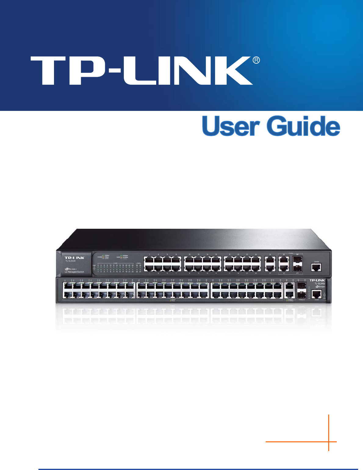
2.3 Appearance Description 2.3.1 Front Panel Figure 2-1 Front Panel of TL-SL3428 Figure 2-2 Front Panel of TL-SL3452 The following parts are located on the front panel: 10/100Mbps Ports: Designed to connect to the device with a bandwidth of 10Mbps or 100Mbps. Each has a corresponding 10/100Mbps LED. 10/100/1000Mbps Ports: Designed to connect to the device with a bandwidth of 10Mbps, 100Mbps or 1000Mbps. Each has a corresponding 1000Mbps LED. SFP Ports: Designed to install the SFP module.
Name Status Indication On A device is linked to the corresponding port, but no activity. Flashing 1000Mbps Data is being transmitted or received. Green The linked device is running at 1000Mbps. Yellow The linked device is running at 10/100Mbps. Off No device is connected to the corresponding port. Note: 1. TL-SL3428 features some “Combo” ports. A “Combo” port consists of a RJ45 port and an SFP port, and the two ports share the same LED. 2.
Chapter 3 Login to the Switch 3.1 Login 1) To access the configuration utility, open a web-browser and type in the default address http://192.168.0.1 in the address field of the browser, then press the Enter key. Figure 3-1 Web-browser Tips: To log in to the switch, the IP address of your PC should be set in the same subnet addresses of the switch. The IP address is 192.168.0.x ("x" is any number from 2 to 254), Subnet Mask is 255.255.255.0.
Figure 3-3 Main Setup-Menu Note: Clicking Apply can only make the new configurations effective before the switch is rebooted. If you want to keep the configurations effective even the switch is rebooted, please click Save Config. You are suggested to click Save Config before cutting off the power or rebooting the switch to avoid losing the new configurations.
Chapter 4 System The System module is mainly for system configuration of the switch, including four submenus: System Info, User Management, System Tools and Access Security. 4.1 System Info The System Info, mainly for basic properties configuration, can be implemented on System Summary, Device Description, System Time, Daylight Saving Time and System IP pages. 4.1.1 System Summary On this page you can view the port connection status and the system information.
Indicates the 1000Mbps port is not connected to a device. Indicates the 1000Mbps port is at the speed of 1000Mbps. Indicates the 1000Mbps port is at the speed of 10Mbps or 100Mbps. Indicates the SFP port is not connected to a device. Indicates the SFP port is at the speed of 1000Mbps. Indicates the SFP port is at the speed of 100Mbps. When the cursor moves on the port, the detailed information of the port will be displayed.
Figure 4-3 Bandwidth Utilization Bandwidth Utilization Rx: Select Rx to display the bandwidth utilization of receiving packets on this port. Tx: Select Tx to display the bandwidth utilization of sending packets on this port. 4.1.2 Device Description On this page you can configure the description of the switch, including device name, device location and system contact. Choose the menu System→System Info→Device Description to load the following page.
Device Location: Enter the location of the switch. System Contact: Enter your contact information. 4.1.3 System Time System Time is the time displayed while the switch is running. On this page you can configure the system time and the settings here will be used for other time-based functions like ACL. You can manually set the system time, get UTC automatically if it has connected to an NTP server or synchronize with PC’s clock as the system time.
Note: 1. The system time will be restored to the default when the switch is restarted and you need to reconfigure the system time of the switch. 2. When Get Time from NTP Server is selected and no time server is configured, the switch will get time from the time server of the Internet if it has connected to the Internet. 4.1.4 Daylight Saving Time Here you can configure the Daylight Saving Time of the switch. Choose the menu System→System Info→Daylight Saving Time to load the following page.
Date Mode: Specify the DST configuration in Date mode. This configuration is recurring in use: Offset: Specify the time adding in minutes when Daylight Saving Time comes. Start/End Time: Select starting time and ending time of Daylight Saving Time. Note: 1. When the DST is disabled, the predefined mode, recurring mode and date mode cannot be configured. 2. When the DST is enabled, the default daylight saving time is of Europe in predefined mode. 4.1.
Management VLAN: Enter the ID of management VLAN, the only VLAN through which you can get access to the switch. By default VLAN1 owning all the ports is the Management VLAN and you can access the switch via any port on the switch. However, if another VLAN is created and set to be the Management VLAN, you may have to reconnect the management station to a port that is a member of the Management VLAN. IP Address: Enter the system IP of the switch. The default system IP is 192.168.0.
settings without the right to configure the switch; the admin can configure all the functions of the switch. The Web management pages contained in this guide are subject to the admin’s login without any explanation. Choose the menu System→User Management→User Config to load the following page. Figure 4-9 User Config The following entries are displayed on this screen: User Info User Name: Create a name for users’ login. Access Level: Select the access level to login.
Operation: Click the Edit button of the desired entry, and you can edit the corresponding user information. After modifying the settings, please click the Modify button to make the modification effective. Access level and user status of the current user information can’t be modified. 4.3 System Tools The System Tools function, allowing you to manage the configuration file of the switch, can be implemented on Config Restore, Config Backup, Firmware Upgrade, System Reboot and System Reset pages. 4.3.
Figure 4-11 Config Backup The following entries are displayed on this screen: Config Backup Backup Config: Click the Backup Config button to save the current configuration as a file to your computer. You are suggested to take this measure before upgrading. Note: It will take a few minutes to backup the configuration. Please wait without any operation. 4.3.3 Firmware Upgrade The switch system can be upgraded via the Web management page.
4. After upgrading, the device will reboot automatically. 5. You are suggested to backup the configuration before upgrading. 4.3.4 System Reboot On this page you can reboot the switch and return to the login page. Please save the current configuration before rebooting to avoid losing the configuration unsaved. Choose the menu System→System Tools→System Reboot to load the following page. Figure 4-13 System Reboot Note: To avoid damage, please don't turn off the device while rebooting. 4.3.
Choose the menu System→Access Security→Access Control to load the following page. Figure 4-15 Access Control The following entries are displayed on this screen: Access Control Config Control Mode: Select the control mode for users to log on to the Web management page. Disable:Disable the access control function. IP-based: Select this option to limit the IP-range of the users for login. MAC-based: Select this option to limit the MAC address of the users for login.
Port: Session Config Session Timeout: The field can be available for configuration only when Port-based mode is selected. Only the users connected to these ports you set here are allowed for login. If you do nothing with the Web management page within the timeout time, the system will log out automatically. If you want to reconfigure, please login again. Access User Number Number Control; Select Enable/Disable the Number Control function.
Figure 4-16 SSL Config The following entries are displayed on this screen: Global Config SSL: Certificate Download Certificate File: Select Enable/Disable the SSL function on the switch. Select the desired certificate to download to the switch. The certificate must be BASE64 encoded. Key Download Key File: Select the desired SSL key to download to the switch. The key must be BASE64 encoded. Note: 1.
an insecure network environment. It can encrypt all the transmission data and prevent the information in a remote management being leaked. Comprising server and client, SSH has two versions, V1 and V2 which are not compatible with each other. In the communication, SSH server and client can auto-negotiate the SSH version and the encryption algorithm.
Key Download Key Type: Select the type of SSH key to download. The switch supports three types: SSH-1 RSA, SSH-2 RSA and SSH-2 DSA. Key File: Select the desired key file to download. Download: Click the Download button to download the desired key file to the switch. Note: 1. Please ensure the key length of the downloaded file is in the range of 256 to 3072 bits. 2. After the key file is downloaded, the user’s original key of the same type will be replaced.
Application Example 2 for SSH: Network Requirements 1. Log on to the switch via password authentication using SSH and the SSH function is enabled on the switch. 2. PuTTY client software is recommended. Configuration Procedure 1. Select the key type and key length, and generate SSH key. Note: 1. The key length is in the range of 256 to 3072 bits. 2. During the key generation, randomly moving the mouse quickly can accelerate the key generation. 3.
2. On the Web management page of the switch, download the public key file saved in the computer to the switch. Note: 1. The key type should accord with the type of the key file. 2. The SSH key downloading can not be interrupted. 3. Download the private key file to SSH client software.
3. After the public key and private key are downloaded, please log on to the interface of PuTTY and enter the IP address for login. 4. After successful authentication, please enter the login user name. If you log on to the switch without entering password, it indicates that the key has been successfully downloaded.
Chapter 5 Switching Switching module is used to configure the basic functions of the switch, including four submenus: Port, LAG, Traffic Monitor and MAC Address. 5.1 Port The Port function, allowing you to configure the basic features for the port, is implemented on the Port Config, Port Mirror, Port Security, Port Isolation and Loopback Detection pages. 5.1.1 Port Config On this page, you can configure the basic parameters for the ports.
Port: Displays the port number. Description: Give a description to the port for identification. Status: Allows you to Enable/Disable the port. When Enable is selected, the port can forward the packets normally. Speed and Duplex: Select the Speed and Duplex mode for the port. The device connected to the switch should be in the same Speed and Duplex mode with the switch. When “Auto” is selected, the Speed and Duplex mode will be determined by auto-negotiation.
Figure5-2 Mirror Group List The following entries are displayed on this screen: Mirror Group List Group: Displays the mirror group number. Mirroring: Displays the mirroring port number. Mode: Displays the mirror mode. Mirrored Port: Displays the mirrored ports. Operation: Click Edit to configure the mirror group. Click Edit to display the following figure.
Figure 5-3 Port Mirror Config The following entries are displayed on this screen. Mirror Group Number: Mirroring Port Mirroring Port: Select the mirror group number you want to configure. Select a port from the pull-down list as the mirroring port. When Disable is selected, the Port Mirror feature will be disabled. Mirrored Port Port Select: Click the Select button to quick-select the corresponding port based on the port number you entered.
Egress: Select Enable/Disable the Egress feature. When the Egress is enabled, the outgoing packets sent by the mirrored port will be copied to the mirroring port. LAG: Displays the LAG number which the port belongs to. The LAG member can not be selected as the mirrored port or mirroring port. Note: 1. The LAG member can not be selected as the mirrored port or mirroring port. 2. A port can not be set as the mirrored port and the mirroring port simultaneously. 3.
Figure 5-4 Port Security The following entries are displayed on this screen: Port Security Select: Select the desired port for Port Security configuration. It is multi-optional. Port: Displays the port number. Max Learned MAC: Specify the maximum number of MAC addresses that can be learned on the port. Learned Num: Displays the number of MAC addresses that have been learned on the port. Learn Mode: Select the Learn Mode for the port.
Note: 1. The Port Security function is disabled for the LAG port member. Only the port is removed from the LAG, will the Port Security function be available for the port. 2. The Port Security function is disabled when the 802.1X function is enabled. 5.1.4 Port Isolation Port Isolation provides a method of restricting traffic flow to improve the network security by forbidding the port to forward packets to the ports that are not on its forward portlist.
Forward Portlist: Select the port that to be forwarded to. Port Isolation List Port: Display the port number. Forward Portlist: Display the forwardlist. 5.1.5 Loopback Detection With loopback detection feature enabled, the switch can detect loops using loopback detection packets. When a loop is detected, the switch will display an alert or further block the corresponding port according to the port configuration. Choose the menu Switching→Port→Loopback Detection to load the following page.
Global Config LoopbackDetection Status: Here you can enable or disable loopback detection function globally. Detection Interval: Set a loopback detection interval between 1 and 1000 seconds. By default, it’s 30 seconds. Automatic Recovery Time : Time after which the blocked port would automatically recover to normal status. It can be set as integral times of detection interval. Web Status : Refresh Here you can enable or disable web automatic refresh.
For the member ports in an aggregation group, their basic configuration must be the same. The basic configuration includes STP, QoS, GVRP, VLAN, port attributes, MAC Address Learning mode and other associated settings. The further explains are following: If the ports, which are enabled for the GVRP, 802.1Q VLAN, Voice VLAN, STP, QoS, Port Isolation, DHCP Snooping and Port Configuration (Speed and Flow Control), are in a LAG, their configurations should be the same.
Figure 5-7 LAG Table The following entries are displayed on this screen: Global Config Hash Algorithm: Select the applied scope of Aggregate Arithmetic, which results in choosing a port to transfer the packets. SRC MAC + DST MAC: When this option is selected, the Aggregate Arithmetic will apply to the source and destination MAC addresses of the packets. SRC IP + DST IP: When this option is selected, the Aggregate Arithmetic will apply to the source and destination IP addresses of the packets.
Figure 5-8 Detail Information 5.2.2 Static LAG On this page, you can manually configure the LAG. The LACP feature is disabled for the member ports of the manually added Static LAG. Choose the menu Switching→LAG→Static LAG to load the following page. Figure 5-9 Manually Config The following entries are displayed on this screen: LAG Config Group Number: Select a Group Number for the LAG.
Description: Displays the description of the LAG. LAG Table Member Port: Select the port as the LAG member. Clearing all the ports of the LAG will delete this LAG. Tips: 1. The LAG can be deleted by clearing its all member ports. 2. A port can only be added to a LAG. If a port is the member of a LAG or is dynamically aggregated as the LACP member, the port number will be displayed in gray and can not be selected. 5.2.3 LACP Config LACP (Link Aggregation Control Protocol) is defined in IEEE802.
Figure 5-10 LACP Config The following entries are displayed on this screen: Global Config System Priority: Specify a System Priority for the port. The System Priority and the Admin Key constitute the aggregation ID. A dynamic aggregation group will only be formed between ports having the same aggregation ID. LACP Config Port Select: Click the Select button to quick-select the corresponding port based on the port number you entered. Select: Select the desired port for LACP configuration.
preferred one. If the two port priorities are equal; the port with smaller port number is preferred. Mode: Specify the LACP mode for your selected port. Status: Enable/Disable the LACP feature for your selected port. LAG: Displays the LAG number which the port belongs to. 5.3 Traffic Monitor The Traffic Monitor function, monitoring the traffic of each port, is implemented on the Traffic Summary and Traffic Statistics pages. 5.3.
Refresh Rate: Enter a value in seconds to specify the refresh interval. Traffic Summary Port Select: Click the Select button to quick-select the corresponding port based on the port number you entered. Port: Displays the port number. Packets Rx: Displays the number of packets received on the port. The error packets are not counted in. Packets Tx: Displays the number of packets transmitted on the port. Octets Rx: Displays the number of octets received on the port.
The following entries are displayed on this screen: Auto Refresh Auto Refresh: Allows you to Enable/Disable refreshing the Traffic Summary automatically. Refresh Rate: Enter a value in seconds to specify the refresh interval. Statistics Port: Enter a port number and click the Select button to view the traffic statistics of the corresponding port. Received: Displays the details of the packets received on the port. Sent: Displays the details of the packets transmitted on the port.
5.4 MAC Address The main function of the switch is forwarding the packets to the correct ports based on the destination MAC address of the packets. Address Table contains the port-based MAC address information, which is the base for the switch to forward packets quickly. The entries in the Address Table can be updated by auto-learning or configured manually. Most the entries are generated and updated by auto-learning.
Figure 5-13 Address Table The following entries are displayed on this screen: Search Option MAC Address: Enter the MAC address of your desired entry. VLAN ID: Enter the VLAN ID of your desired entry. Port: Select the corresponding port number of your desired entry. Type: Select the type of your desired entry. All: This option allows the address table to display all the address entries. Static: This option allows the address table to display the static address entries only.
Address Table MAC Address: Displays the MAC address learned by the switch. VLAN ID: Displays the corresponding VLAN ID of the MAC address. Port: Displays the corresponding Port number of the MAC address. Type: Displays the Type of the MAC address. Aging Status: Displays the Aging status of the MAC address. 5.4.2 Static Address The static address table maintains the static address entries which can be added or removed manually, independent of the aging time.
Search Option Search Option: Select a Search Option from the pull-down list and click the Search button to find your desired entry in the Static Address Table. MAC Address: Enter the MAC address of your desired entry. VLAN ID: Enter the VLAN ID number of your desired entry. Port: Enter the Port number of your desired entry. Static Address Table Select: Select the entry to delete or modify the corresponding port number. It is multi-optional. MAC Address: Displays the static MAC address.
Figure 5-15 Dynamic Address The following entries are displayed on this screen: Aging Config Auto Aging: Allows you to Enable/Disable the Auto Aging feature. Aging Time: Enter the Aging Time for the dynamic address. Search Option Search Option: Select a Search Option from the pull-down list and click the Search button to find your desired entry in the Dynamic Address Table. MAC Address: Enter the MAC address of your desired entry. VLAN ID: Enter the VLAN ID number of your desired entry.
Dynamic Address Table Select: Select the entry to delete the dynamic address or to bind the MAC address to the corresponding port statically. It is multi-optional. MAC Address: Displays the dynamic MAC address. VLAN ID: Displays the corresponding VLAN ID of the MAC address. Port: Displays the corresponding port number of the MAC address. Type: Displays the Type of the MAC address. Aging Status: Displays the Aging Status of the MAC address.
The following entries are displayed on this screen: Create Filtering Address MAC Address: Enter the MAC address to be filtered. VLAN ID: Enter the corresponding VLAN ID of the MAC address. Search Option Search Option: Select a Search Option from the pull-down list and click the Search button to find your desired entry in the Filtering Address Table. MAC Address: Enter the MAC address of your desired entry. VLAN ID: Enter the VLAN ID number of your desired entry.
Chapter 6 VLAN The traditional Ethernet is a data network communication technology basing on CSMA/CD (Carrier Sense Multiple Access/Collision Detect) via shared communication medium. Through the traditional Ethernet, the overfull hosts in LAN will result in serious collision, flooding broadcasts, poor performance or even breakdown of the Internet.
VLANs. The switch can analyze the received untagged packets on the port and match the packets with the Protocol VLAN and 802.1Q VLAN in turn. If a packet is matched, the switch will add a corresponding VLAN tag to it and forward it in the corresponding VLAN. 6.1 802.1Q VLAN VLAN tags in the packets are necessary for the switch to identify packets of different VLANs.
(2) TRUNK: The TRUNK port can be added in multiple VLANs, and the egress rule of the port is TAG. The TRUNK port is generally used to connect the cascaded network devices for it can receive and forward the packets of multiple VLANs. When the packets are forwarded by the TRUNK port, its VLAN tag will not be changed. (3) GENERAL: The GENERAL port can be added in multiple VLANs and set various egress rules according to the different VLANs. The default egress rule is UNTAG.
IEEE 802.1Q VLAN function is implemented on the VLAN Config and Port Config pages. 6.1.1 VLAN Config On this page, you can view the current created 802.1Q VLAN. Choose the menu VLAN→802.1Q VLAN→VLAN Config to load the following page. Figure 6-3 VLAN Table To ensure the normal communication of the factory switch, the default VLAN of all ports is set to VLAN1. VLAN1 can not be modified or deleted.
Figure 6-4 Create or Modify 802.1Q VLAN The following entries are displayed on this screen: VLAN Config VLAN ID: Enter the ID number of VLAN. Description: Give a description to the VLAN for identification. Check: Click the Check button to check whether the VLAN ID you entered is valid or not. VLAN Members Port Select: Click the Select button to quick-select the corresponding entry based on the port number you entered. Select: Select the desired port to be a member of VLAN or leave it blank.
Egress Rule: LAG: Select the Egress Rule for the VLAN port member. The default egress rule is UNTAG. TAG: All packets forwarded by the port are tagged. The packets contain VLAN information. UNTAG: Packets forwarded by the port are untagged. Displays the LAG to which the port belongs. 6.1.2 Port Config Before creating the 802.1Q VLAN, please acquaint yourself with all the devices connected to the switch in order to configure the ports properly. Choose the menu VLAN→802.
Link Type: Select the Link Type from the pull-down list for the port. ACCESS: The ACCESS port can be added in a single VLAN, and the egress rule of the port is UNTAG. The PVID is same as the current VLAN ID. If the current VLAN is deleted, the PVID will be set to 1 by default. TRUNK: The TRUNK port can be added in multiple VLANs, and the egress rule of the port is TAG. The PVID can be set as the VID number of any VLAN the port belongs to.
Step Operation Description 2 Create VLAN. Required. On the VLAN→802.1Q VLAN→VLAN Config page, click the Create button to create a VLAN. Enter the VLAN ID and the description for the VLAN. Meanwhile, specify its member ports. 3 Modify/View VLAN. Optional. On the VLAN→802.1Q VLAN→VLAN Config page, click the Edit/Detail button to modify/view the information of the corresponding VLAN. 4 Delete VLAN Optional. On the VLAN→802.
3. If the Protocol VLAN is created, please set its enabled port to be the member of corresponding 802.1Q VLAN so as to ensure the packets forwarded normally. 6.2.1 Protocol VLAN On this page, you can create Protocol VLAN and view the information of the current defined Protocol VLANs. Choose the menu VLAN→Protocol VLAN→Protocol VLAN to load the following page.
Figure 6-8 Create and View Protocol Template The following entries are displayed on this screen: Create Protocol Template Protocol Name: Give a name for the Protocol Template. Ether Type: Enter the Ethernet protocol type field in the protocol template. Protocol Template Table Select: Select the desired entry. It is multi-optional. Protocol Name: Displays the name of the protocol template. Ether Type: Displays the Ethernet protocol type field in the protocol template.
Figure 6-9 Enable Protocol VLAN for Port Port Enable: Select your desired port for Protocol VLAN feature. All the ports are disabled by default. Configuration Procedure: Step Operation Description 1 Set the link type for port. Required. On the VLAN→802.1Q VLAN→Port Config page, set the link type for the port basing on its connected device. 2 Create VLAN. Required. On the VLAN→802.1Q VLAN→VLAN Config page, click the Create button to create a VLAN.
GARP GARP provides the mechanism to assist the switch members in LAN to deliver, propagate and register the information among the members. GARP itself does not work as the entity among the devices. The application complied with GARP is called GARP implementation, and GVRP is the implementation of GARP. When GARP is implemented on a port of device, the port is called GARP entity. The information exchange between GARP entities is completed by messages.
including VLAN members, ports through which the VLAN members can be reached, and so on. The switch also propagates the local VLAN registration information to other switches so that all the switching devices in the same switched network can have the same VLAN information. The VLAN registration information includes not only the static registration information configured locally, but also the dynamic registration information, which is received from other switches.
Note: If the GVRP feature is enabled for a member port of LAG, please ensure all the member ports of this LAG are set to be in the same status and registration mode. The following entries are displayed on this screen: Global Config GVRP: Allows you to Enable/Disable the GVRP function. Port Config Port Select: Click the Select button to quick-select the corresponding entry based on the port number you entered. Select: Select the desired port for configuration. It is multi-optional.
Configuration Procedure: Step Operation Description 1 Set the link type for port. Required. On the VLAN→802.1Q VLAN→Port Config page, set the link type of the port to be TRUNK. 2 Enable GVRP function. Required. On the VLAN→GVRP page, enable GVRP function. 3 Configure the registration mode and the timers for the port. Required. On the VLAN→GVRP page, configure the parameters of ports basing on actual applications. 6.4 Application Example for 802.
Step Operation Description 2 Create VLAN10 Required. On VLAN→802.1Q VLAN→VLAN Config page, create a VLAN with its VLAN ID as 10, owning Port 2 and Port 3. 3 Create VLAN20 Required. On VLAN→802.1Q VLAN→VLAN Config page, create a VLAN with its VLAN ID as 20, owning Port 3 and Port 4. Configure Switch B Step Operation Description 1 Configure the Link Type of the ports Required. On VLAN→802.
Configuration Procedure Configure Switch A Step Operation Description 1 Configure the Link Type of the ports Required. On VLAN→802.1Q VLAN→Port Config page, configure the link type of Port 11 and Port 13 as ACCESS, and configure the link type of Port 12 as GENERAL. 2 Create VLAN10 Required. On VLAN→802.1Q VLAN→VLAN Config page, create a VLAN with its VLAN ID as 10, owning Port 12 and Port 13, and configure the egress rule of Port 12 as Untag. 3 Create VLAN20 Required. On VLAN→802.
Chapter 7 Spanning Tree STP (Spanning Tree Protocol), subject to IEEE 802.1D standard, is to disbranch a ring network in the Data Link layer in a local network. Devices running STP discover loops in the network and block ports by exchanging information, in that way, a ring network can be disbranched to form a tree-topological ring-free network to prevent packets from being duplicated and forwarded endlessly in the network. BPDU (Bridge Protocol Data Unit) is the protocol data that STP and RSTP use.
Port: Port 3 is the root port of switch B and port 5 is the root port of switch C; port 1 is the designated port of switch A and port 4 is the designated port of switch B; port 6 is the blocked port of switch C. Figure 7-1 Basic STP diagram STP Timers Hello Time: Hello Time ranges from 1 to 10 seconds. It specifies the interval to send BPDU packets. It is used to test the links. Max. Age: Max. Age ranges from 6 to 40 seconds.
STP Generation In the beginning In the beginning, each switch regards itself as the root, and generates a configuration BPDU for each port on it as a root, with the root path cost being 0, the ID of the designated bridge being that of the switch, and the designated port being itself. Comparing BPDUs Each switch sends out configuration BPDUs and receives a configuration BPDU on one of its ports from another switch. The following table shows the comparing operations.
Tips: In an STP with stable topology, only the root port and designated port can forward data, and the other ports are blocked. The blocked ports only can receive BPDUs. RSTP (Rapid Spanning Tree Protocol), evolved from the 802.1D STP standard, enable Ethernet ports to transit their states rapidly. The premises for the port in the RSTP to transit its state rapidly are as follows.
Figure 7-2 Basic MSTP diagram MSTP MSTP divides a network into several MST regions. The CST is generated between these MST regions, and multiple spanning trees can be generated in each MST region. Each spanning tree is called an instance. As well as STP, MSTP uses BPDUs to generate spanning tree. The only difference is that the BPDU for MSTP carries the MSTP configuration information on the switches.
Figure 7-3 Port roles The Spanning Tree module is mainly for spanning tree configuration of the switch, including four submenus: STP Config, Port Config, MSTP Instance and STP Security. 7.1 STP Config The STP Config function, for global configuration of spanning trees on the switch, can be implemented on STP Config and STP Summary pages. 7.1.1 STP Config Before configuring spanning trees, you should make clear the roles each switch plays in each spanning tree instance.
Figure 7-4 STP Config The following entries are displayed on this screen: Global Config STP: Select Enable/Disable STP function globally on the switch. Version: Select the desired STP version on the switch. STP: Spanning Tree Protocol. RSTP: Rapid Spanning Tree Protocol. MSTP: Multiple Spanning Tree Protocol. Parameters Config CIST Priority: Enter a value from 0 to 61440 to specify the priority of the switch for comparison in the CIST.
Max Hops: Enter a value from 1 to 40 to set the maximum number of hops that occur in a specific region before the BPDU is discarded. The default value is 20 hops. Note: 1. The forward delay parameter and the network diameter are correlated. A too small forward delay parameter may result in temporary loops. A too large forward delay may cause a network unable to resume the normal state in time. The default value is recommended. 2.
Figure 7-5 STP Summary 7.2 Port Config On this page you can configure the parameters of the ports for CIST Choose the menu Spanning Tree→Port Config to load the following page.
Figure 7-6 Port Config The following entries are displayed on this screen: Port Config Port Select: Click the Select button to quick-select the corresponding port based on the port number you entered. Select: Select the desired port for STP configuration. It is multi-optional. Port: Displays the port number of the switch. Status: Select Enable /Disable STP function for the desired port. Priority: Enter a value from 0 to 240 divisible by 16.
Port Status: Displays the working status of the port. LAG: Designated Port: Indicates the port that forwards packets to a downstream network segment or switch. Master Port: Indicates the port that connects a MST region to the common root. The path from the master port to the common root is the shortest path between this MST region and the common root. Alternate Port: Indicates the port that can be a backup port of a root or master port.
Figure 7-7 Region Config The following entries are displayed on this screen: Region Config Region Name: Create a name for MST region identification using up to 32 characters. Revision: Enter the revision from 0 to 65535 for MST region identification. 7.3.2 Instance Config Instance Configuration, a property of MST region, is used to describe the VLAN to Instance mapping configuration. You can assign VLAN to different instances appropriate to your needs.
The following entries are displayed on this screen: Instance Table Instance ID Select: Click the Select button to quick-select the corresponding Instance ID based on the ID number you entered. Select: Select the desired Instance ID for configuration. It is multi-optional. Instance: Displays Instance ID of the switch. Status: Displays the status of the corresponding instance. Priority: Enter the priority of the switch in the instance.
Figure 7-9 Instance Port Config The following entries are displayed on this screen: Port Config Instance ID: Select the desired instance ID for its port configuration. Port Select: Click the Select button to quick-select the corresponding port based on the port number you entered. Select: Select the desired port to specify its priority and path cost. It is multi-optional. Port: Displays the port number of the switch. Priority: Enter the priority of the port in the instance.
Note: The port status of one port in different spanning tree instances can be different. Global configuration Procedure for Spanning Tree function: Step Operation Description 1 Make clear roles the switches play in spanning tree instances: root bridge or designated bridge Preparation. 2 Globally configure parameters MSTP Required. Enable Spanning Tree function on the switch and configure MSTP parameters on Spanning Tree→STP Config→STP Config page. 3 Configure MSTP parameters for ports Required.
Root Protect A CIST and its secondary root bridges are usually located in the high-bandwidth core region. Wrong configuration or malicious attacks may result in configuration BPDU packets with higher priorities being received by the legal root bridge, which causes the current legal root bridge to lose its position and network topology jitter to occur. In this case, flows that should travel along high-speed links may lead to low-speed links, and network congestion may occur.
Figure 7-10 Port Protect The following entries are displayed on this screen: Port Protect Port Select: Click the Select button to quick-select the corresponding port based on the port number you entered. Select: Select the desired port for port protect configuration. It is multi-optional. Port: Displays the port number of the switch. Loop Protect: Loop Protect is to prevent the loops in the network brought by recalculating STP because of link failures and network congestions.
7.4.2 TC Protect When TC Protect is enabled for the port on Port Protect page, the TC threshold and TC protect cycle need to be configured on this page. Choose the menu Spanning Tree→STP Security→TC Protect to load the following page. Figure 7-11 TC Protect The following entries are displayed on this screen: TC Protect TC Threshold: Enter a number from 1 to 100. It is the maximum number of the TC-BPDUs received by the switch in a TC Protect Cycle. The default value is 20.
Network Diagram Configuration Procedure Configure Switch A: Step Operation Description 1 Configure ports On VLAN→802.1Q VLAN page, configure the link type of the related ports as Trunk, and add the ports to VLAN 101-VLAN 106. The detailed instructions can be found in the section 802.1Q VLAN. 2 Enable STP function On Spanning Tree→STP Config→STP Config page, enable STP function and select MSTP version. On Spanning Tree→STP Config→Port Config page, enable MSTP function for the port.
Step Operation Description 3 Configure the region name and the revision of MST region On Spanning Tree→MSTP Instance→Region Config page, configure the region as TP-LINK and keep the default revision setting. 4 Configure VLAN-to-Instance mapping table of the MST region On Spanning Tree→MSTP Instance→Instance Config page, configure VLAN-to-Instance mapping table. Map VLAN 101, 103 and 105 to Instance 1; map VLAN 102, 104 and 106 to Instance 2.
Step 2 Operation Description Enable STP function On Spanning Tree→STP Config→STP Config page, enable STP function and select MSTP version. On Spanning Tree→STP Config→Port Config page, enable MSTP function for the port. 3 Configure the region name and the revision of MST region On Spanning Tree→MSTP Instance→Region Config page, configure the region as TP-LINK and keep the default revision setting.
Enable Loop Protect function for the non-edge ports. Enable BPDU Protect function or BPDU Filter function for the edge ports which are connected to the PC and server.
Chapter 8 Multicast Multicast Overview In the network, packets are sent in three modes: unicast, broadcast and multicast. In unicast, the source server sends separate copy information to each receiver. When a large number of users require this information, the server must send many pieces of information with the same content to the users. Therefore, large bandwidth will be occupied. In broadcast, the system transmits information to all users in a network.
Multicast Address 1. Multicast IP Address: As specified by IANA (Internet Assigned Numbers Authority), Class D IP addresses are used as destination addresses of multicast packets. The multicast IP addresses range from 224.0.0.0~239.255.255.255. The following table displays the range and description of several special multicast IP addresses. Multicast IP address range Description 224.0.0.0~224.0.0.255 Reserved multicast addresses for routing protocols and other network protocols 224.0.1.0~224.0.1.
VLAN ID Multicast IP Port Figure 8-3 Multicast Address Table IGMP Snooping In the network, the hosts apply to the near Router for joining (leaving) a multicast group by sending IGMP (Internet Group Management Protocol) messages. When the up-stream device forwards down the multicast data, the switch is responsible for sending them to the hosts. IGMP Snooping is a multicast control mechanism, which can be used on the switch for dynamic registration of the multicast group.
it will be added to the multicast address table with its member port time specified; if the receiving port is already a member port, its member port time will be directly reset. 3. IGMP Leave Message The host, running IGMPv1, does not send IGMP leave message when leaving a multicast group, as a result, the switch can not get the leave information of the host momentarily.
Figure 8-4 Basic Config The following entries are displayed on this screen: Global Config IGMP Snooping: Select Enable/Disable IGMP Snooping function globally on the switch. Unknown Multicast: Select the operation for the switch to process unknown multicast, Forward or Discard. IGMP Snooping Status Description: Displays IGMP Snooping status. Member: Displays the member of the corresponding status. 8.1.2 Port Config On this page you can configure the IGMP feature for ports of the switch.
Figure 8-5 Port Config The following entries are displayed on this screen: Port Config Port Select: Click the Select button to quick-select the corresponding port based on the port number you entered. Select: Select the desired port for IGMP Snooping feature configuration. It is multi-optional. Port: Displays the port of the switch. IGMP Snooping: Select Enable/Disable IGMP Snooping for the desired port. Fast Leave: Select Enable/Disable Fast Leave feature for the desired port.
Choose the menu Multicast→IGMP Snooping→VLAN Config to load the following page. Figure 8-6 VLAN Config The following entries are displayed on this screen: VLAN Config VLAN ID: Enter the VLAN ID to enable IGMP Snooping for the desired VLAN. Router Port Time: Specify the aging time of the router port. Within this time, if the switch doesn’t receive IGMP query message from the router port, it will consider this port is not a router port any more.
Leave Time: Displays the leave time of the VLAN. Router Port: Displays the router port of the VLAN. Note: The settings here will be invalid when multicast VLAN is enabled. Configuration procedure: Step Operation 1 Enable function Snooping Required. Enable IGMP Snooping globally on the switch and for the port on Multicast→IGMP Snooping→Snooping Config and Port Config page. 2 Configure the multicast parameters for VLANs Optional.
Figure 8-7 Multicast VLAN The following entries are displayed on this screen: Multicast VLAN Multicast VLAN: Select Enable/Disable Multicast VLAN feature. VLAN ID: Enter the VLAN ID of the multicast VLAN. Router Port Time: Specify the aging time of the router port. Within this time, if the switch doesn’t receive IGMP query message from the router port, it will consider this port is not a router port any more. Member Port Time: Specify the aging time of the member port.
Configuration procedure: Step Operation 1 Enable IGMP function 2 Create a multicast VLAN 3 Description Snooping Configure parameters multicast VLAN Required. Enable IGMP Snooping globally on the switch and for the port on Multicast→IGMP Snooping→Snooping Config and Port Config page. Required. Create a multicast VLAN and add all the member ports and router ports to the VLAN on the VLAN→802.1Q VLAN page. for Configure the link type of the member ports as GENERAL.
Network Diagram Configuration Procedure Step Operation Description 1 Create VLANs Create three VLANs with the VLAN ID 3, 4 and 5 respectively, and specify the description of VLAN3 as Multicast VLAN on VLAN→802.1Q VLAN page. 2 Configure ports On VLAN→802.1Q VLAN function pages. For port 3, configure its link type as GENERAL and its egress rule as TAG, and add it to VLAN3, VLAN4 and VLAN5.
8.2 Multicast IP In a network, receivers can join different multicast groups appropriate to their needs. The switch forwards multicast streams based on multicast address table. The Multicast IP can be implemented on Multicast IP Table, Static Multicast IP page. 8.2.1 Multicast IP Table On this page you can view the multicast IP table on the switch. Choose the menu Multicast→Multicast IP→Multicast IP Table to load the following page.
Note: If the configuration on VLAN Config page and multicast VLAN page is changed, the switch will clear up the dynamic multicast addresses in multicast address table and learn new addresses. 8.2.2 Static Multicast IP Static Multicast IP table, isolated from dynamic multicast group and multicast filter, is not learned by IGMP Snooping. It can enhance the quality and security for information transmission in some fixed multicast groups.
Static Multicast IP Table Select: Select the desired entry to delete the corresponding static multicast IP. It is multi-optional. Multicast IP: Displays the multicast IP. VLAN ID: Displays the VLAN ID of the multicast group. Forward Port: Displays the forward port of the multicast group. 8.3 Multicast Filter When IGMP Snooping is enabled, you can specified the multicast IP-range the ports can join so as to restrict users ordering multicast programs via configuring multicast filter rules.
IP-Range Table IP-Range ID Select: Click the Select button to quick-select the corresponding IP-range ID based on the ID number you entered. Select: Select the desired entry to delete or modify the corresponding IP-range. It is multi-optional. IP-Range ID: Displays IP-range ID. Start Multicast IP: Displays start multicast IP of the IP-range. End Multicast IP: Displays end multicast IP of the IP-range. 8.3.2 Port Filter On this page you can configure the multicast filter rules for port.
Action Mode: Select the action mode to process multicast packets when the multicast IP is in the filtering IP-range. Permit: Only the multicast packets whose multicast IP is in the IP-range will be processed. Deny: Only the multicast packets whose multicast IP is not in the IP-range will be processed. Bound IP-Range (ID): Enter the IP-rang ID the port will be bound to. Max Groups: Specify the maximum number of multicast groups to prevent some ports taking up too much bandwidth.
Figure 8-12 Packet Statistics The following entries are displayed on this screen: Auto Refresh Auto Refresh: Select Enable/Disable auto refresh feature. Refresh Period: Enter the time from 3 to 300 in seconds to specify the auto refresh period. IGMP Statistics Port Select: Click the Select button to quick-select the corresponding port based on the port number you entered. Port: Displays the port number of the switch. Query Packet: Displays the number of query packets the port received.
Chapter 9 QoS QoS (Quality of Service) functions to provide different quality of service for various network applications and requirements and optimize the bandwidth resource distribution so as to provide a network service experience of a better quality. QoS This switch classifies the ingress packets, maps the packets to different priority queues and then forwards the packets according to specified scheduling algorithms to implement QoS function.
2. 802.1P Priority Figure 9-2 802.1Q frame As shown in the figure above, each 802.1Q Tag has a Pri field, comprising 3 bits. The 3-bit priority field is 802.1p priority in the range of 0 to 7. 802.1P priority determines the priority of the packets based on the Pri value. On the Web management page of the switch, you can configure different priority tags mapping to the corresponding priority levels, and then the switch determine which packet is sent preferentially when forwarding packets.
Figure 9-4 SP-Mode 2. WRR-Mode: Weight Round Robin Mode. In this mode, packets in all the queues are sent in order based on the weight value for each queue and every queue can be assured of a certain service time. The weight value indicates the occupied proportion of the resource. WRR queue overcomes the disadvantage of SP queue that the packets in the queues with lower priority can not get service for a long time.
The QoS module is mainly for traffic control and priority configuration, including three submenus: DiffServ, Bandwidth Control and Voice VLAN. 9.1 DiffServ This switch classifies the ingress packets, maps the packets to different priority queues and then forwards the packets according to specified scheduling algorithms to implement QoS function. This switch implements three priority modes based on port, on 802.1P and on DSCP, and supports four queue scheduling algorithms.
Note: To complete QoS function configuration, you have to go to the Schedule Mode page to select a schedule mode after the configuration is finished on this page. Configuration Procedure: Step Operation Description 1 Log on to the Port Priority page 2 Select the desired ports for configuration Select the desired ports. It is multi-optional. 3 Select the port priority Required. Select a priority from CoS0 to CoS7. 4 Select a schedule mode Required.
Figure 9-7 DSCP Priority The following entries are displayed on this screen: DSCP Priority Config DSCP Priority: Select Enable or Disable DSCP Priority. Priority Level DSCP: Indicates the priority determined by the DS region of IP datagram. It ranges from 0 to 63. Priority Level: Indicates the priority level the packets with tag are mapped to. The priority levels are labeled as TC0, TC1, TC2 and TC3.
Step Operation Description 3 Map the DSCP priority to the priority level Required. Select DSCP priority and the corresponding priority level. 4 Select a schedule mode Required. Log on to the Schedule Mode page to select a schedule mode. 9.1.3 802.1P/CoS Mapping On this page you can configure the mapping relation between the 802.1P priority tag-id/CoS-id and the TC-id. 802.1P gives the Pri field in 802.1Q tag a recommended definition.
Note: To complete QoS function configuration, you have to go to the Schedule Mode page to select a schedule mode after the configuration is finished on this page. Configuration Procedure: Step Operation Description 1 Configure the mapping relation between the 802.1P priority Tag/CoS and the TC Required. On QoS→DiffServ→802.1P/CoS mapping page, configure the mapping relation between the 802.1P priority Tag/CoS and the TC. 2 Select a schedule mode Required.
Equ-Mode: Equal-Mode. In this mode, all the queues occupy the bandwidth equally. The weight value ratio of all the queues is 1:1:1:1. 9.2 Bandwidth Control Bandwidth function, allowing you to control the traffic rate and broadcast flow on each port to ensure network in working order, can be implemented on Rate Limit and Storm Control pages. 9.2.1 Rate Limit Rate limit functions to control the ingress/egress traffic rate on each port via configuring the available bandwidth of each port.
Ingress Rate(Kbps): Configure the bandwidth for receiving packets on the port. You can select a rate from the dropdown list or select "Manual" to set Ingress rate, the system will automatically select integral multiple of 64Kbps that closest to the rate you entered as the real Ingress rate. Egress Rate(Kbps): Configure the bandwidth for sending packets on the port.
Figure 9-11 Storm Control The following entries are displayed on this screen: Storm Control Config Port Select: Click the Select button to quick-select the corresponding port based on the port number you entered. Select: Select the desired port for Storm Control configuration. It is multi-optional. Port: Displays the port number of the switch. Broadcast: Enable/Disable broadcast control feature for the port. Multicast: Enable/Disable multicast control feature for the port.
configuration for voice data, ensuring the transmission priority of voice data stream and voice quality. OUI Address (Organizationally unique identifier address) The switch can determine whether a received packet is a voice packet by checking its source MAC address. If the source MAC address of a packet complies with the OUI addresses configured by the system, the packet is determined as voice packet and transmitted in voice VLAN.
Port Voice VLAN Voice Link type of the port and processing mode Mode Stream Type Automatic Mode TAG voice ACCESS: Not supported. stream TRUNK: Supported. The default VLAN of the port can not be voice VLAN. GENERAL: Supported. The default VLAN of the port can not be voice VLAN and the egress rule of the access port in the voice VLAN should be TAG. UNTAG voice ACCESS: Supported. stream TRUNK: Not supported. GENERAL: Supported.
The following entries are displayed on this screen: Global Config Voice VLAN: Select Enable/Disable Voice VLAN function. VLAN ID: Enter the VLAN ID of the voice VLAN. Aging Time: Specifies the living time of the member port in auto mode after the OUI address is aging out. 9.3.2 Port Config Before the voice VLAN function is enabled, the parameters of the ports in the voice VLAN should be configured on this page. Choose the menu QoS→Voice VLAN→Port Config to load the following page.
The following entries are displayed on this screen: Port Config Port Select: Click the Select button to quick-select the corresponding port based on the port number you entered. Select: Select the desired port for voice VLAN configuration. It is multi-optional. Port: Displays the port number of the switch. Port Mode: Select the mode for the port to join the voice VLAN.
Figure 9-14 OUI Configuration The following entries are displayed on this screen: Create OUI OUI: Enter the OUI address of the voice device. Mask: Enter the OUI address mask of the voice device. Description: Give a description to the OUI for identification. OUI Table Select: Select the desired entry to view the detailed information. OUI: Displays the OUI address of the voice device. Mask: Displays the OUI address mask of the voice device. Description: Displays the description of the OUI.
Step Operation Description 4 Configure the parameters of the ports in voice VLAN Required. On QoS→Voice VLAN→Port Config configure the parameters of the ports in voice VLAN. 5 Enable Voice VLAN Required. On QoS→Voice VLAN→Global Config page, configure the global parameters of voice VLAN.
Chapter 10 ACL ACL (Access Control List) is used to filter packets by configuring match rules and process policies of packets in order to control the access of the illegal users to the network. Besides, ACL functions to control traffic flows and save network resources. It provides a flexible and secured access control policy and facilitates you to control the network security.
10.1.2 Time-Range Create On this page you can create time-ranges. Choose the menu ACL→Time-Range→Time-Range Create to load the following page. Figure 10-2 Time-Range Create The following entries are displayed on this screen: Create Time-Range Name: Enter the name of the time-range for time identification. Holiday: Select Holiday you set as a time-range. The ACL rule based on this time-range takes effect only when the system time is within the holiday.
10.1.3 Holiday Config Holiday mode is applied as a different secured access control policy from the week mode. On this page you can define holidays according to your work arrangement. Choose the menu ACL→Time-Range→Holiday Config to load the following page. Figure 10-3 Holiday Configuration The following entries are displayed on this screen: Create Holiday Start Date: Specify the start date of the holiday. End Date: Specify the end date of the holiday.
10.2.1 ACL Summary On this page, you can view the current ACLs configured in the switch. Choose the menu ACL→ACL Config→ACL Summary to load the following page. Figure 10-4 ACL Summary The following entries are displayed on this screen: Search Option Select ACL: Select the ACL you have created ACL Type: Displays the type of the ACL you select. Rule Order: Displays the rule order of the ACL you select. Rule Table Display the rule table of the ACL you have selected.
10.2.3 MAC ACL MAC ACLs analyze and process packets based on a series of match conditions, which can be the source MAC addresses, destination MAC addresses, VLAN ID, and EtherType carried in the packets. Choose the menu ACL→ACL Config→MAC ACL to load the following page. Figure 10-6 Create MAC Rule The following entries are displayed on this screen: Create MAC ACL ACL ID: Select the desired MAC ACL for configuration. Rule ID: Enter the rule ID.
10.2.4 Standard-IP ACL Standard-IP ACLs analyze and process data packets based on a series of match conditions, which can be the source IP addresses and destination IP addresses carried in the packets. Choose the menu ACL→ACL Config→Standard-IP ACL to load the following page. Figure 10-7 Create Standard-IP Rule The following entries are displayed on this screen: Create Standard-IP ACL ACL ID: Select the desired Standard-IP ACL for configuration. Rule ID: Enter the rule ID.
Figure 10-8 Create Extend-IP Rule The following entries are displayed on this screen: Create Extend-IP ACL ACL ID: Select the desired Extend-IP ACL for configuration. Rule ID: Enter the rule ID. Operation: Select the operation for the switch to process packets which match the rules. Permit: Forward packets. Deny: Discard Packets. S-IP: Enter the source IP address contained in the rule. D-IP: Enter the destination IP address contained in the rule. Mask: Enter IP address mask.
10.3 Policy Config A Policy is used to control the data packets those match the corresponding ACL rules by configuring ACLs and actions together for effect. The operations here include stream mirror, stream condition, QoS remarking and redirect. The Policy Config can be implemented on Policy Summary, Police Create and Action Create pages. 10.3.1 Policy Summary On this page, you can view the ACL and the corresponding operations in the policy.
Figure 10-10 Create Policy The following entries are displayed on this screen: Create Policy Policy Name: Enter the name of the policy. 10.3.3 Action Create On this page you can add ACLs and create corresponding actions for the policy. Choose the menu ACL→Policy Config→Action Create to load the following page. Figure 10-11 Action Create The following entries are displayed on this screen: Create Action Select Policy: Select the name of the policy.
S-Condition: Select S-Condition to limit the transmission rate of the data packets in the policy. Redirect: Rate: Specify the forwarding rate of the data packets those match the corresponding ACL. Out of Band: Specify the disposal way of the data packets those are transmitted beyond the rate. Select Redirect to change the forwarding direction of the data packets in the policy. Destination Port: Forward the data packets those match the corresponding ACL to the specific port. 10.
10.4.2 Port Binding On this page you can bind a policy to a port. Choose the menu ACL→Policy Binding→Port Binding to load the following page. Figure 10-13 Bind the policy to the port The following entries are displayed on this screen: Port-Bind Config Policy Name: Select the name of the policy you want to bind. Port: Enter the number of the port you want to bind. Port-Bind Table Index: Displays the index of the binding policy. Policy Name: Displays the name of the binding policy.
VLAN-Bind Config Policy Name: Select the name of the policy you want to bind. VLAN ID: Enter the ID of the VLAN you want to bind. VLAN-Bind Table Index: Displays the index of the binding policy. Policy Name: Displays the name of the binding policy. VLAN ID: Displays the ID of the VLAN bound to the corresponding policy. Direction: Displays the binding direction. Configuration Procedure: Step Operation Description 1 Configure time-range 2 Configure ACL rules Required.
Network Diagram Configuration Procedure Step Operation Description 1 Configure Time-range On ACL→Time-Range page, create a time-range named work_time. Select Week mode and configure the week time from Monday to Friday. Add a time-slice 08:00~18:00. 2 Configure for requirement 1 On ACL→ACL Config→ACL Create page, create ACL 11.
Step Operation Description 3 Configure requirement and 4 for 2 On ACL→ACL Config→ACL Create page, create ACL 100. On ACL→ACL Config→Standard-IP ACL page, select ACL 100, create Rule 1, configure operation as Deny, configure S-IP as 10.10.70.0 and mask as 255.255.255.0, configure D-IP as 10.10.50.0 and mask as 255.255.255.0, configure the time-range as No Limit. On ACL→ACL Config→Standard-IP ACL page, select ACL 100, create Rule 2, configure operation as Permit, configure S-IP as 10.10.70.
Chapter 11 Network Security Network Security module is to provide the multiple protection measures for the network security, including five submenus: IP-MAC Binding, ARP Inspection, DoS Defend and 802.1X. Please configure the functions appropriate to your need. 11.1 IP-MAC Binding The IP-MAC Binding function allows you to bind the IP address, MAC address, VLAN ID and the connected Port number of the Host together.
The following entries are displayed on this screen: Search Option Source: Select a Source from the pull-down list and click the Search button to view your desired entry in the Binding Table. All: All the bound entries will be displayed. Manual: Only the manually added entries will be displayed. Scanning: Only the entries formed via ARP Scanning will be displayed. Snooping: Only the entries formed via DHCP Snooping will be displayed.
Figure 11-2 Manual Binding The following entries are displayed on this screen: Manual Binding Option Host Name: Enter the Host Name. IP Address: Enter the IP address of the Host. MAC Address: Enter the MAC address of the Host. VLAN ID: Enter the VLAN ID. Port: Select the number of port connected to the Host. Protect Type: Select the Protect Type for the entry. Manual Binding Table Select: Select the desired entry to be deleted. It is multi-optional.
11.1.3 ARP Scanning ARP (Address Resolution Protocol) is used to analyze and map IP addresses to the corresponding MAC addresses so that packets can be delivered to their destinations correctly. IP address is the address of the Host on Network layer. MAC address, the address of the Host on Data link layer, is necessary for the packet to reach the very device. So the destination IP address carried in a packet need to be translated into the corresponding MAC address.
Figure 11-4 ARP Scanning The following entries are displayed on this screen: Scanning Option Start IP Address: Specify the Start IP address. End IP Address: Specify the End IP address. VLAN ID: Enter the VLAN ID. If blank, the switch will send the untagged packets for scanning. Scan: Click the Scan button to scan the Hosts in the LAN. Scanning Result Select: Select the desired entry to be bound or deleted. Host Name: Displays the Host Name here.
network configuration protocol optimized and developed basing on the BOOTP, functions to solve the above mentioned problems. DHCP Working Principle DHCP works via the “Client/Server” communication mode. The Client applies to the Server for configuration. The Server assigns the configuration information, such as the IP address, to the Client, so as to reach a dynamic employ of the network source. A Server can assign the IP address for several Clients, which is illustrated in the following figure.
Figure 11-6 Interaction between a DHCP client and a DHCP server (1) DHCP-DISCOVER Stage: The Client broadcasts the DHCP-DISCOVER packet to find the DHCP Server. (2) DHCP-OFFER Stage: Upon receiving the DHCP-DISCOVER packet, the DHCP Server selects an IP address from the IP pool according to the assigning priority of the IP addresses and replies to the Client with DHCP-OFFER packet carrying the IP address and other information.
Option 82 can contain 255 sub-options at most. If Option 82 is defined, at least a sub-option should be defined. This switch supports two sub-options: Circuit ID and Remote ID. Since there is no universal standard about the content of Option 82, different manufacturers define the sub-options of Option 82 to their need. For this switch, the sub-options are defined as the following: The Circuit ID is defined to be the number of the port which receives the DHCP Request packets and its VLAN number.
Choose the menu Network Security→IP-MAC Binding→DHCP Snooping to load the following page. Figure 11-8 DHCP Snooping Note: If you want to enable the DHCP Snooping feature for the member port of LAG, please ensure the parameters of all the member ports are the same. The following entries are displayed on this screen: DHCP Snooping Config DHCP Snooping: Enable/Disable the DHCP Snooping function globally.
Global Flow Control: Select the value to specify the maximum amount of DHCP messages that can be forwarded by the switch per second. The excessive massages will be discarded. Decline Threshold: Select the value to specify the minimum transmission rate of the Decline packets to trigger the Decline protection for the specific port. Decline Flow Control: Select the value to specify the Decline Flow Control.
11.2 ARP Inspection According to the ARP Implementation Procedure stated in 11.1.3 ARP Scanning, it can be found that ARP protocol can facilitate the Hosts in the same network segment to communicate with one another or access to external network via Gateway. However, since ARP protocol is implemented with the premise that all the Hosts and Gateways are trusted, there are high security risks during ARP Implementation Procedure in the actual complex network.
Figure 11-10 ARP Attack – Cheating Gateway As the above figure shown, the attacker sends the fake ARP packets of Host A to the Gateway, and then the Gateway will automatically update its ARP table after receiving the ARP packets. When the Gateway tries to communicate with Host A in LAN, it will encapsulate this false destination MAC address for packets, which results in a breakdown of the normal communication.
Figure 11-11 ARP Attack – Cheating Terminal Hosts As the above figure shown, the attacker sends the fake ARP packets of Host A to Host B, and then Host B will automatically update its ARP table after receiving the ARP packets. When Host B tries to communicate with Host A, it will encapsulate this false destination MAC address for packets, which results in a breakdown of the normal communication.
Figure 11-12 Man-In-The-Middle Attack Suppose there are three Hosts in LAN connected with one another through a switch. Host A: IP address is 192.168.0.101; MAC address is 00-00-00-11-11-11. Host B: IP address is 192.168.0.102; MAC address is 00-00-00-22-22-22. Attacker: IP address is 192.168.0.103; MAC address is 00-00-00-33-33-33. 1. First, the attacker sends the false ARP response packets. 2. Upon receiving the ARP response packets, Host A and Host B updates the ARP table of their own. 3.
The IP-MAC Binding function allows the switch to bind the IP address, MAC address, VLAN ID and the connected Port number of the Host together when the Host connects to the switch. Basing on the predefined IP-MAC Binding entries, the ARP Inspection functions to detect the ARP packets and filter the illegal ARP packet so as to prevent the network from ARP attacks. The ARP Inspection function is implemented on the ARP Detect, ARP Defend and ARP Statistics pages. 11.2.
Configuration Procedure: Step Operation Description 1 Bind the IP address, MAC address, VLAN ID and the connected Port number of the Host together. Required. On the IP-MAC Binding page, bind the IP address, MAC address, VLAN ID and the connected Port number of the Host together via Manual Binding, ARP Scanning or DHCP Snooping. 2 Enable the protection for the bound entry. Required. On the Network Security→IP-MAC Binding→Binding Table page, specify a protect type for the corresponding bound entry.
The following entries are displayed on this screen: ARP Defend Port Select: Click the Select button to quick-select the corresponding port based on the port number you entered. Select: Select your desired port for configuration. It is multi-optional. Port: Displays the port number. Defend: Select Enable/Disable the ARP Defend feature for the port. Speed: Enter a value to specify the maximum amount of the received ARP packets per second.
Figure 11-15 ARP Statistics The following entries are displayed on this screen: Auto Refresh Auto Refresh: Enable/Disable the Auto Refresh feature. Refresh Interval: Specify the refresh interval to display the ARP Statistics. Illegal ARP Packet Port: Displays the port number. Trusted Port: Indicates the port is an ARP Trusted Port or not. Illegal ARP Packet: Displays the number of the received illegal ARP packets. 11.
DoS Attack Type Description Scan SYNFIN The attacker sends the packet with its SYN field and the FIN field set to 1. The SYN field is used to request initial connection whereas the FIN field is used to request disconnection. Therefore, the packet of this type is illegal. The switch can defend this type of illegal packet. Xmascan The attacker sends the illegal packet with its TCP index, FIN, URG and PSH field set to 1.
Config DoS Protection: Allows you to Enable/Disable DoS Defend function. Defend Table Select: Select the entry to enable the corresponding Defend Type. Defend Type: Displays the Defend Type name. Tips: You are suggested to take the following further steps to ensure the network security. 1. It’s recommended to inspect and repair the system vulnerability regularly. It is also necessary to install the system bulletins and backup the important information in time. 2.
An 802.1X authentication is initiated when a user launches client program on the supplicant system. Note that the client program must support the 802.1X authentication protocol. (2) Authenticator System: The authenticator system is usually an 802.1X-supported network device, such as this TP-LINK switch. It provides the physical or logical port for the supplicant system to access the LAN and authenticates the supplicant system.
Figure 11-18 EAP-MD5 Authentication Procedure 1. A supplicant system launches an 802.1X client program via its registered user name and password to initiate an access request through the sending of an EAPOL-Start packet to the switch. The 802.1X client program then forwards the packet to the switch to start the authentication process. 2. Upon receiving the authentication request packet, the switch sends an EAP-Request/Identity packet to ask the 802.1X client program for the user name. 3. The 802.
8. The supplicant system can also terminate the authenticated state by sending EAPOL-Logoff packets to the switch. The switch then changes the port state from accepted to rejected. (2) EAP Terminating Mode In this mode, packet transmission is terminated at authenticator systems and the EAP packets are mapped into RADIUS packets. Authentication and accounting are accomplished through RADIUS protocol. In this mode, PAP or CHAP is employed between the switch and the RADIUS server.
Guest VLAN Guest VLAN function enables the supplicants that do not pass the authentication to access the specific network resource. By default, all the ports connected to the supplicants belong to a VLAN, i.e. Guest VLAN. Users belonging to the Guest VLAN can access the resources of the Guest VLAN without being authenticated. But they need to be authenticated before accessing external resources.
Auth Method: Select the Authentication Method from the pull-down list. EAP-MD5: IEEE 802.1X authentication system uses extensible authentication protocol (EAP) to exchange information between the switch and the client. The EAP protocol packets with authentication data can be encapsulated in the advanced protocol (such as RADIUS) packets to be transmitted to the authentication server. PAP: IEEE 802.
Figure 11-21 Port Config The following entries are displayed on this screen: Port Config Port Select: Click the Select button to quick-select the corresponding port based on the port number you entered. Select: Select your desired port for configuration. It is multi-optional. Port: Displays the port number. Status: Select Enable/Disable the 802.1X authentication feature for the port. Guest VLAN: Select Enable/Disable the Guest VLAN feature for the port.
Authorized: Displays the authentication status of the port. LAG: Displays the LAG to which the port belongs to. 11.4.3 Radius Server RADIUS (Remote Authentication Dial-In User Service) server provides the authentication service for the switch via the stored client information, such as the user name, password, etc, with the purpose to control the authentication and accounting status of the clients. On this page, you can configure the parameters of the authentication server.
Note: 1. The 802.1X function takes effect only when it is enabled globally on the switch and for the port. 2. The 802.1X function can not be enabled for LAG member ports. That is, the port with 802.1X function enabled can not be added to the LAG. 3. The 802.1X function should not be enabled for the port connected to the authentication server. In addition, the authentication parameters of the switch and the authentication server should be the same.
Chapter 12 SNMP SNMP Overview SNMP (Simple Network Management Protocol) has gained the most extensive application on the UDP/IP networks. SNMP provides a management frame to monitor and maintain the network devices. It is used for automatically managing the various network devices no matter the physical differences of the devices. Currently, the most network management systems are based on SNMP.
SNMP v1: SNMP v1 adopts Community Name authentication. The community name is used to define the relation between SNMP Management Station and SNMP Agent. The SNMP packets failing to pass community name authentication are discarded. The community name can limit access to SNMP Agent from SNMP NMS, functioning as a password. SNMP v2c: SNMP v2c also adopts community name authentication. It is compatible with SNMP v1 while enlarges the function of SNMP v1.
The User configured in an SNMP Group can manage the switch via the client program on management station. The specified User Name and the Auth/Privacy Password are used for SNMP Management Station to access the SNMP Agent, functioning as the password. SNMP module is used to configure the SNMP function of the switch, including three submenus: SNMP Config, Notification and RMON. 12.1 SNMP Config The SNMP Config can be implemented on the Global Config, SNMP View, SNMP Group, SNMP User and SNMP Community pages.
Note: The amount of Engine ID characters must be even. 12.1.2 SNMP View The OID (Object Identifier) of the SNMP packets is used to describe the managed objects of the switch, and the MIB (Management Information Base) is the set of the OIDs. The SNMP View is created for the SNMP management station to manage MIB objects. Choose the menu SNMP→SNMP Config→SNMP View to load the following page.
12.1.3 SNMP Group On this page, you can configure SNMP Group to control the network access by providing the users in various groups with different management rights via the Read View, Write View and Notify View. Choose the menu SNMP→SNMP Config→SNMP Group to load the following page. Figure 12-5 SNMP Group The following entries are displayed on this screen: Group Config Group Name: Enter the SNMP Group name. The Group Name, Security Model and Security Level compose the identifier of the SNMP Group.
writing only and changes can be made to the assigned SNMP View. The View defined both as the Read View and the Write View can be read and modified. Notify View: Select the View to be the Notify View. The management station can receive notification messages of the assigned SNMP view generated by the switch's SNMP agent. Group Table Select: Select the desired entry to delete the corresponding group. It's multi-optional. Group Name: Displays the Group Name here.
Figure 12-6 SNMP User The following entries are displayed on this screen: User Config User Name: Enter the User Name here. User Type: Select the type for the User. Local User: Indicates that the user is connected to a local SNMP engine. Remote User: Indicates that the user is connected to a remote SNMP engine. Group Name: Select the Group Name of the User. The User is classified to the corresponding Group according to its Group Name, Security Model and Security Level.
User Table Select: Select the desired entry to delete the corresponding User. It is multi-optional. User Name: Displays the name of the User. User Type: Displays the User Type. Group Name: Displays the Group Name of the User. Security Model: Displays the Security Model of the User. Security Level: Displays the Security Level of the User. Auth Mode: Displays the Authentication Mode of the User. Privacy Mode: Displays the Privacy Mode of the User.
MIB View: read-only: Management right of the Community is restricted to read-only, and changes cannot be made to the corresponding View. read-write: Management right of the Community is read-write and changes can be made to the corresponding View. Select the MIB View for the community to access. Community Table Select: Select the desired entry to delete the corresponding Community. It is multi-optional. Community Name: Displays the Community Name here.
Step Operation Description 2 Create SNMP View. Required. On the SNMP→SNMP Config→SNMP View page, create SNMP View of the management agent. The default View Name is viewDefault and the default OID is 1. 3 Create SNMP Community directly. Configure access level for the User. Required alternatively. On the SNMP→SNMP Config→SNMP Community page, create SNMP Community based on SNMP v1 and SNMP v2c. Create SNMP Group and SNMP User. Create SNMP Community directly. Create SNMP Group and SNMP User.
Figure 12-8 Notification Config The following entries are displayed on this screen: Create Notification IP Address: Enter the IP address of the management Host. UDP Port: Enter the number of the UDP port used to send notifications. The UDP port functions with the IP address for the notification sending. The default is 162. User: Enter the User name of the management station. Security Model: Select the Security Model of the management station.
Notification Table Select: Select the desired management station. entry to delete the corresponding IP Address: Displays the IP address of the management host. UDP Port: Displays the UDP port used to send notifications. User: Displays the User name of the management station. Security Model: Displays the Security Model of the management station. Security Level: Displays the Security Level for the SNMP v3 User. Type: Displays the type of the notifications.
The RMON Groups can be configured on the History Control, Event Config and Alarm Config pages. 12.3.1 History Control On this page, you can configure the History Group for RMON. Choose the menu SNMP→RMON→History Control to load the following page. Figure 12-9 History Control The following entries are displayed on this screen: History Control Table Select: Select the desired entry for configuration. Index: Displays the index number of the entry.
Figure 12-10 Event Config The following entries are displayed on this screen: Event Table Select: Select the desired entry for configuration. Index: Displays the index number of the entry. User: Enter the name of the User or the community to which the event belongs. Description: Give a description to the event for identification. Type: Select the event type, which determines the act way of the network device in response to an event. None: No processing. Log: Logging the event.
Figure 12-11 Alarm Config The following entries are displayed on this screen: Alarm Table Select: Select the desired entry for configuration. Index: Displays the index number of the entry. Variable: Select the alarm variables from the pull-down list. Port: Select the port on which the Alarm entry acts. Sample Type: Specify the sampling method for the selected variable and comparing the value against the thresholds.
Interval: Enter the alarm interval time in seconds. Owner: Enter the name of the device or user that defined the entry. Status: Select Enable/Disable the corresponding alarm entry. Note: When alarm variables exceed the Threshold on the same direction continuously for several times, an alarm event will only be generated on the first time, that is, the Rising Alarm and Falling Alarm are triggered alternately for that the alarm following to Rising Alarm is certainly a Falling Alarm and vice versa.
Chapter 13 LLDP LLDP (Link Layer Discovery Protocol) is a Layer 2 protocol that is used for network devices to advertise their own device information periodically to neighbors on the same IEEE 802 local area network. The advertised information, including details such as device identification, capabilities and configuration settings, is represented in TLV (Type/Length/Value) format according to the IEEE 802.1ab standard, and these TLVs are encapsulated in LLDPDU (Link Layer Discovery Protocol Data Unit).
Disable: the port cannot transmit or receive LLDPDUs. 2) 3) LLDPDU transmission mechanism If the ports are working in TxRx or Tx mode, they will advertise local information by sending LLDPDUs periodically. If there is a change in the local device, the change notification will be advertised.
TLV Type TLV Name Description Usage in LLDPDU 3 Time To Live Indicates the number of seconds that the neighbor device is to regard the local information to be valid. Mandatory 4 Port Description Identifies the description string of the port. Optional 5 System Name Identifies the system name. Optional 6 System Description Identifies the system description. Optional 7 System Capabilities Identifies the main functions of the system and the functions enabled.
System Name TLV The System Name TLV allows network management to advertise the system's assigned name, which should be the system's fully qualified domain name. Management TLV The Management Address TLV identifies an address associated with the local LLDP agent that may be used to reach higher entities to assist discovery by network management.
Figure 13-1 Global Configuration The following entries are displayed on this screen: Global Config LLDP: Enable/disable LLDP function globally. Parameters Config Transmit Interval: Enter the interval for the local device to transmit LLDPDU to its neighbors. The default value is 30 seconds. Hold Multiplier: Enter a multiplier on the Transmit Interval. It determines the actual TTL (Time To Live) value used in an LLDPDU. TTL = Hold Multiplier * Transmit Interval. The default value is 4.
Figure 13-2 Port Configuration The following entries are displayed on this screen: LLDP Port Config Port Select: Select the desired port to configure. Admin Status: Select the port’s LLDP operating mode: Tx&Rx: Send and receive LLDP frames. Rx_Only: Only receive LLDP frames. Tx_Only: Only send LLDP frames. Disable: Neither send nor receive LLDP frames. Notification Mode: Enable/Disable the ports' SNMP notification.
Figure 13-3 Local Information The following entries are displayed on this screen: Auto Refresh Auto Refresh: Enable/Disable the auto refresh function. Refresh Rate: Specify the auto refresh rate. Local Info Enter the desired port number and click Select to display the information of the corresponding port. 13.2.2 Neighbor Info On this page you can get the information of the neighbors. Choose the menu LLDP→Device Info→Neighbor Info to load the following page.
The following entries are displayed on this screen: Auto Refresh Auto Refresh: Enable/Disable the auto refresh function. Refresh Rate: Specify the auto refresh rate. Neighbor Info Port Select: Click the Select button to quick-select the corresponding port based on the port number you entered. Local Port: Displays the local port number connecting to the neighbor device. System Name: Displays the system name of the neighbor device. Chassis ID: Displays the Chassis ID of the neighbor device.
Figure 13-5 Device Statistics The following entries are displayed on this screen: Auto Refresh Auto Refresh: Enable/Disable the auto refresh function. Refresh Rate: Specify the auto refresh rate. Global Statistics Last Update: Displays latest update time of the statistics. Total Inserts: Displays the number of neighbors inserted till last update time. Total Deletes: Displays the number of neighbors deleted by local device.
Receive Total: Displays the number of LLDPDUs received by this port. Discards: Displays the number of LLDPDUs discarded by this port. Errors: Displays the number of error LLDPDUs received by this port. Ageouts: Displays the number of overtime neighbors linking to this port. TLV Discards: Displays the number of TLVs dropped by this port. TLV Unknowns: Displays the number of unknown TLVs received by this port.
Chapter 14 Cluster With the development of network technology, the network scale is getting larger and more network devices are required, which may result in a more complicated network management system. As a large number of devices need to be assigned different network addresses and every management device needs to be respectively configured to meet the application requirements, manpower are needed. The Cluster Management function can solve the above problem.
The commander switch discovers and determines candidate switches by collecting related information. After being added to the cluster, the candidate switch becomes to be the member switch. After being removed from the cluster, the member switch becomes to be the candidate switch. The commander switch becomes to be the candidate switch only when the cluster is deleted.
The following entries are displayed on this screen: Neighbor Search Option: Select the information the desired entry should contain and then click the Search button to display the desired entry in the following Neighbor Information table. Neighbor Info Native Port: Displays the port number of the switch. Remote Port: Displays the port number of the neighbor switch which is connected to the corresponding port. Device Name: Displays the name of the neighbor switch.
Figure 14-3 NDP Summary The following entries are displayed on this screen: Global Config NDP: Displays the global NDP status (enabled or disabled) for the switch. Aging Time: Displays the period for the neighbor switch to keep the NDP packets from this switch. Hello Time: Displays the interval to send NDP packets. Port Status Port: Displays the port number of the switch. NDP: Displays the NDP status (enabled or disabled) for the current port.
Detail: Click the Detail button to view the complete information collected for the port. 14.1.3 NDP Config On this page you can configure the NDP function for the switch. Choose the menu Cluster→NDP→NDP Config to load the following page. Figure 14-4 NDP Config The following entries are displayed on this screen: Global Config NDP: Select Enable/Disable NDP function globally. Aging Time: Enter the period for the neighbor switch to keep the NDP packets from this switch.
NDP: Displays NDP status of the current port. Enable: Click the Enable button to enable NDP for the port you select. Disable: Click the Disable button to disable NDP for the port you select. Note: 1. NDP function is effective only when NDP function is enabled globally and for the port. 2. The aging time should be set over the hello time value, otherwise the neighbor information table of NDP ports will not take effect. 14.
Device Table Device Type: Displays the device description collected through NTDP. Device MAC: Displays the MAC address of this device. Cluster Name: Displays the cluster name of this device. Role: Displays the role this device plays in the cluster. Commander: Indicates the device that can configure and manage all the devices in a cluster. Member: Indicates the device that is managed in a cluster.
Figure 14-7 NTDP Summary The following entries are displayed on this screen: Global Config NTDP: Displays the NTDP status (enabled or disabled) of the switch globally. NTDP Interval Time: Displays the interval to collect topology information. NTDP Hops: Displays the hop count the switch topology collects. NTDP Hop Delay: Displays the time between the switch receiving NTDP request packets and the switch forwarding NTDP request packets for the first time.
Port Status Port: Displays the port number of the switch. NTDP: Displays NTDP status (enabled or disabled) of the current port. 14.2.3 NTDP Config On this page you can configure NTDP globally. Choose the menu Cluster→NTDP→NTDP Config to load the following page. Figure 14-8 NTDP Config The following entries are displayed on this screen: Global Config NTDP: Select Enable/Disable NTDP for the switch globally. NTDP Interval Time: Enter the interval to collect topology information.
NTDP Hops: Enter the hop count the switch topology collects. The default is 3 hops. NTDP Hop Delay: Enter the time between the switch receiving NTDP request packets and the switch forwarding NTDP request packets for the first time. The default is 200 milliseconds. NTDP Port Delay: Enter the time between the port forwarding NTDP request packets and its adjacent port forwarding NTDP request packets over. The default is 20 milliseconds.
The following entries are displayed on this screen: Global Cluster: Displays the cluster status (enabled or disabled) of the switch. Cluster Role: Displays the role the switch plays in the cluster. For a member switch, the following page is displayed: Figure 14-10 Cluster Summary for Member Switch The following entries are displayed on this screen: Global Config Cluster: Displays the cluster status (enabled or disabled) of the switch.
Cluster Role: Displays the role the switch plays in the cluster. 14.3.2 Cluster Config On this page you can configure the status of the cluster the switch belongs to. Choose the menu Cluster→Cluster→Cluster Config to load the following page. For a candidate switch, the following page is displayed.
Role Change Individual: Select this option to change the role of the switch to be individual switch. For an individual switch, the following page is displayed. Figure 14-14 Cluster Configuration for Individual Switch The following entries are displayed on this screen: Current Role Role: Displays the role the current switch plays in the cluster. Role Change Candidate: Select this option to change the role of the switch to be candidate switch. 14.
Network Diagram Figure 14-15 Network diagram Configuration Procedure Configure the member switch Step Operation Description 1 Enable NDP function on the switch and for port 1 On Cluster→NDP→NDP Config page, enable NDP function. 2 Enable NTDP function on the switch and for port 1 On Cluster→NTDP→NTDP Config page, enable NTDP function.
Step Operation Description 4 Configure the member switch On Cluster→Cluster→Member Config page, select the member switch and click the Manage button to log on to its Web management page. Or On Cluster→Cluster→Cluster Topology page, double-click the switch icon to view its detailed information; click the switch icon and click the Manage button to log on to the Web management page.
Chapter 15 Maintenance Maintenance module, assembling the commonly used system tools to manage the switch, provides the convenient method to locate and solve the network problem. (1) System Monitor: Monitor the utilization status of the memory and the CPU of switch. (2) Log: View the configuration parameters of the switch and find out the errors via the Logs. (3) Cable Test: Test the connection status of the cable to locate and diagnose the trouble spot of the network.
Click the Monitor button to enable the switch to monitor and display its CPU utilization rate every four seconds. 15.1.2 Memory Monitor Choose the menu Maintenance→System Monitor→Memory Monitor to load the following page. Figure 15-2 Memory Monitor Click the Monitor button to enable the switch to monitor and display its Memory utilization rate every four seconds. 15.
informational 6 Informational messages debugging 7 Debug-level messages Table 15-1 Log Level The Log function is implemented on the Log Table, Local Log, Remote Log and Backup Log pages. 15.2.1 Log Table The switch supports logs output to two directions, namely, log buffer and log file. The information in log buffer will be lost after the switch is rebooted or powered off whereas the information in log file will be kept effective even the switch is rebooted or powered off.
15.2.2 Local Log Local Log is the log information saved in switch. By default, all system logs are saved in log buffer and the logs with severities from level_0 to level_4 are saved in log file meanwhile. On this page, you can set the output channel for logs. Choose the menu Maintenance→Log→Local Log to load the following page. Figure 15-4 Local Log The following entries are displayed on this screen: Local Log Config Select: Select the desired entry to configure the corresponding local log.
Figure 15-5 Log Host The following entries are displayed on this screen: Log Host Select: Select the desired entry to configure the corresponding log host. Index: Displays the index of the log host. The switch supports 4 log hosts. Host IP: Configure the IP for the log host. UDP Port: Displays the UDP port used for receiving/sending log information. Here we use the standard port 514. Severity: Specify the severity level of the log information sent to each log host.
Figure 15-6 Backup Log The following entry is displayed on this screen: Backup Log Backup Log: Click the Backup Log button to save the log as a file to your computer. Note: It will take a few minutes to backup the log file. Please wait without any operation. 15.3 Device Diagnostics This switch provides Cable Test and Loopback functions for device diagnostics. 15.3.
Pair: Displays the Pair number. Status: Displays the connection status of the cable connected to the port. The test results of the cable include normal, close, open, short, impedance or unknown. Length: If the connection status is normal, here displays the length range of the cable. Error: If the connection status is close, open or impedance, here displays the error length of the cable. Note: 1. The Length displayed here is the length of pair cable not that of the physical cable. 2.
Loopback Port Loopback Port: Select the desired port for loopback test. Test: Click the Test button to start the loopback test for the port. 15.4 Network Diagnostics This switch provides Ping test and Tracert test functions for network diagnostics. 15.4.1 Ping Ping test function, testing the connectivity between the switch and one node of the network, facilitates you to test the network connectivity and reachability of the host so as to locate the network malfunctions.
15.4.2 Tracert Tracert test function is used to test the connectivity of the gateways during its journey from the source to destination of the test data. When malfunctions occur to the network, you can locate trouble spot of the network with this tracert test. Choose the menu Maintenance→Network Diagnostics→Tracert to load the following page. Figure 15-10Tracert The following entries are displayed on this screen: Tracert Config Destination IP: Enter the IP address of the destination device.
Chapter 16 System Maintenance via FTP The firmware can be downloaded to the switch via FTP function. FTP (File Transfer Protocol), a protocol in the application layer, is mainly used to transfer files between the remote server and the local PCs. It is a common protocol used in the IP network for files transfer. If there is something wrong with the firmware of the switch and the switch can not be launched, the firmware can be downloaded to the switch again via FTP function. 1.
Figure 16-2 Open Hyper Terminal 2) The Connection Description Window will prompt shown as Figure 16-3. Enter a name into the Name field and click OK. Figure 16-3 Connection Description 3) Select the port to connect in Figure 16-4 and click OK.
Figure 16-4 Select the port to connect 4) Configure the port selected in the step above shown as the following Figure 16-5. Configure Bits per second as 38400, Data bits as 8, Parity as None, Stop bits as 1, Flow control as None, and then click OK. Figure 16-5 Port Settings 3. Download Firmware via booUtil menu To download firmware to the switch via FTP function, you need to enter into the bootUtil menu of the switch and take the following steps.
Figure 16-6 bootUtil Menu As the prompt is displayed for a short time, you are suggested not to release the CTRL-B key until you enter into bootUtil menu after powering on the switch. 3) After entering into bootUtil menu, please firstly configure the IP parameters of the switch. The format is: ifconfig ip xxx.xxx.xxx.xxx mask 255.255.255.0 gateway xxx.xxx.xxx.xxx. For example: Configure the IP address as 172.31.70.22, mask as 255.255.255.0 and gateway as172.31.70.1. The detailed command is shown as below.
Start . . . . . . . . ◀ ****************** User: User Access Login ***************** When you forget the login user name and password, you can enter reset command after entering into bootUtil menu to reset the system. The system will be restored to the factory default settings, and the default login user name and password are both admin.
Appendix A: Specifications IEEE802.3 10Base-T Ethernet IEEE802.3u 100Base-TX/100Base-FX Fast Ethernet IEEE802.3ab 1000Base-T Gigabit Ethernet Standards IEEE802.3z 1000Base-X Gigabit Ethernet IEEE802.3x Flow Control IEEE802.1p QoS IEEE802.1q VLAN IEEE802.1X Port-based Access Authentication Ethernet: 10Mbps HD,20Mbps FD Transmission Rate Fast Ethernet: 100Mbps HD,200Mbps FD Gigabit Ethernet: 2000Mbps FD 10Base-T: UTP/STP of Cat. 3 or above 100Base-TX: UTP/STP of Cat.
Appendix B: Configuring the PCs In this section, we’ll introduce how to install and configure the TCP/IP correctly in Windows 2000. First make sure your Ethernet Adapter is working, refer to the adapter’s manual if necessary. 1. Configure TCP/IP component 1) On the Windows taskbar, click the Start button, and then click Control Panel. 2) Click the Network and Internet Connections icon, and then click on the Network Connections tab in the appearing window.
Figure B-2 5) The following TCP/IP Properties window will display and the IP Address tab is open on this window by default.
Figure B-3 6) Select Use the following IP address. And the following items will be available. If the switch's IP address is 192.168.0.1, specify IP address as 192.168.0.x (x is from 2 to 254), and the Subnet mask as 255.255.255.0. Now: Click OK to save your settings.
Appendix C: 802.1X Client Software In 802.1X mechanism, the supplicant Client should be equipped with the corresponding client software complied with 802.1X protocol standard for 802.1X authentication. When the switch TL-SL3428 works as the authenticator system, please take the following instructions to install the TpSupplicant provided on the attached CD for the supplicant Client. 1.1 Installation Guide 1. Insert the provided CD into your CD-ROM drive.
Figure C-3 Welcome to the InstallShield Wizard 4. To continue, choose the destination location for the installation files and click Next on the following screen. Figure C-4 Choose Destination Location By default, the installation files are saved on the Program Files folder of system disk. Click the Change button to modify the destination location proper to your need. 5. Till now, The Wizard is ready to begin the installation. Click Install to start the installation on the following screen.
Figure C-5 Install the Program 6. The InstallShield Wizard is installing TpSupplicant shown as the following screen. Please wait. Figure C-6 Setup Status 7. On the following screen, click Finish to complete the installation.
Figure C-7 InstallShield Wizard Complete Note: Please pay attention to the tips on the above screen. If you have not installed WinPcap 4.0.2 or the higher version on your computer, the 802.1X Client Software TpSupplicant can not work. It’s recommended to go to http://www.winpcap.org to download the latest version of WinPcap for installation. 1.2 Uninstall Software If you want to remove the TpSupplicant, please take the following steps: 1.
2. Then the following screen will appear. If you want to stop the remove process, click Cancel. Figure C-9 Preparing Setup 3. On the continued screen, click Yes to remove the application from your PC. Figure C-10 Uninstall the Application 4. Click Finish to complete. Figure C-11 Uninstall Complete 1.3 1. Configuration After completing installation, double click the icon Software. The following screen will appear. 232 to run the TP-LINK 802.
Figure C-12 TP-LINK 802.1X Client Enter the Name and the Password specified in the Authentication Server. The length of Name and Password should be less than 16 characters. 2. Click the Properties button on Figure C-12 to load the following screen for configuring the connection properties. Figure C-13 Connection Properties Send 802.1X protocol packets by Unicast: When this option is selected, the Client will send the EAPOL Start packets to the switch via multicast and send the 802.
3. To continue, click Connect button after entering the Name and Password on Figure C-12. Then the following screen will appear to prompt that the Radius server is being searched. Figure C-14 Authentication Dialog 4. When passing the authentication, the following screen will appear. Figure C-15 Successfully Authenticated 5. on the right corner of desktop, and then the following connection Double click the icon status screen will pop up. Figure C-16 Connection Status 1.
A1: It’s because the supported DLL file is missing. You are suggested to go to http://www.winpcap.org to download WinPcap 4.0.2 or the higher version for installation, and run the client software again. Q2: Is this TP-LINK 802.1X Client Software compliable with the switches of the other manufacturers? A2: No. This TP-LINK 802.1X Client Software is customized for TP-LINK switches. Q3: Is it safe to set the password being automatically saved? A3: Yes.
Appendix D: Glossary Access Control List (ACL) ACLs can limit network traffic and restrict access to certain users or devices by checking each packet for certain IP or MAC (i.e., Layer 2) information. Boot Protocol (BOOTP) BOOTP is used to provide bootup information for network devices, including IP address information, the address of the TFTP server that contains the devices system files, and the name of the boot file.
Generic Multicast Registration Protocol (GMRP) GMRP allows network devices to register end stations with multicast groups. GMRP requires that any participating network devices or end stations comply with the IEEE 802.1p standard. Group Attribute Registration Protocol (GARP) See Generic Attribute Registration Protocol. IEEE 802.1D Specifies a general method for the operation of MAC bridges, including the Spanning Tree Protocol. IEEE 802.
Layer 2 Data Link layer in the ISO 7-Layer Data Communications Protocol. This is related directly to the hardware interface for network devices and passes on traffic based on MAC addresses. Link Aggregation See Port Trunk. Link Aggregation Control Protocol (LACP) Allows ports to automatically negotiate a trunked link with LACP-configured ports on another device. Management Information Base (MIB) An acronym for Management Information Base.
Secure Shell (SSH) A secure replacement for remote access functions, including Telnet. SSH can authenticate users with a cryptographic key, and encrypt data connections between management clients and the switch. Simple Network Management Protocol (SNMP) The application protocol in the Internet suite of protocols which offers network management services. Simple Network Time Protocol (SNTP) SNTP allows a device to set its internal clock based on periodic updates from a Network Time Protocol (NTP) server.