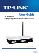
TL-WA5110G 54Mbps High Power Wireless Access Point Rev: 2.0.
COPYRIGHT & TRADEMARKS Specifications are subject to change without notice. is a registered trademark of TP-LINK TECHNOLOGIES CO., LTD. Other brands and product names are trademarks or registered trademarks of their respective holders. No part of the specifications may be reproduced in any form or by any means or used to make any derivative such as translation, transformation, or adaptation without permission from TP-LINK TECHNOLOGIES CO., LTD. Copyright © 2010 TP-LINK TECHNOLOGIES CO., LTD.
FCC STATEMENT This equipment has been tested and found to comply with the limits for a Class B digital device, pursuant to part 15 of the FCC Rules. These limits are designed to provide reasonable protection against harmful interference in a residential installation. This equipment generates, uses and can radiate radio frequency energy and, if not installed and used in accordance with the instructions, may cause harmful interference to radio communications.
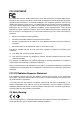
National Restrictions 2400.0-2483.5 MHz Country Restriction General authorization required for outdoor use and public service Bulgaria France Outdoor use limited to 10 mW e.i.r.p. within the band 2454-2483.5 MHz Norway Military Radiolocation use. Refarming of the 2.4 GHz band has been ongoing in recent years to allow current relaxed regulation.
TP-LINK TECHNOLOGIES CO., LTD DECLARATION OF CONFORMITY For the following equipment: Product Description: 54Mbps High Power Wireless Access Point Model No.: TL-WA5110G Trademark: TP-LINK We declare under our own responsibility that the above products satisfy all the technical regulations applicable to the product within the scope of Council Directives: Directives 1999/5/EC The above product is in conformity with the following standards or other normative documents ETSI EN 300 328 V1.7.
CONTENTS Package Contents ................................................................................................................................. 1 Chapter 1 Product Overview...........................................................................................................2 1.1 Overview of the Product........................................................................................................... 2 1.2 Features ................................................................
4.8 Wireless settings....................................................................................................................38 4.9 Forwarding .............................................................................................................................38 4.9.1 Virtual Servers................................................................................................................39 4.9.2 Port Triggering.................................................................
5.6 Wireless .................................................................................................................................70 5.6.1 Basic Settings.................................................................................................................70 5.6.2 Wireless Mode................................................................................................................72 5.6.3 Security Settings ..................................................................
Package Contents The following items should be found in your package: ¾ One TL-WA5110G 54Mbps High Power Wireless Access Point ¾ One power Adapter for TL-WA5110G 54Mbps High Power Wireless Access Point ¾ One Power Injector ¾ Mounting Kits ¾ Quick Installation Guide ¾ One Resource CD for TL-WA5110G 54Mbps High Power Wireless Access Point, including: z This User Guide z Other helpful information ) Note: Make sure that the package contains the above items.
Chapter 1 Product Overview Thank you for choosing TL-WA5110G 54Mbps High Power Wireless Access Point. 1.1 Overview of the Product The TL-WA5110G 54Mbps High Power Wireless Access Point is dedicated to Small Office/Home Office (SOHO) wireless network solutions. The TL-WA5110G 54Mbps High Power Wireless Access Point will allow you to connect your network with other wireless devices wirelessly, sharing Internet Access, files and fun, easily and securely.
¾ Supports Remote Management. ¾ Output transmit power adjustable. ¾ Supports PPPoE, Dynamic IP, Static IP Internet Access. ¾ Built-in NAT and DHCP server supporting static IP address distributing. ¾ Supports UPnP, Dynamic DNS, Static Routing, VPN Pass-through. ¾ Supports Virtual Server, Special Application and DMZ host. ¾ Built-in firewall supporting IP address filtering, Domain Name filtering, and MAC address filtering. ¾ Provides WLAN ACL (Access Control List).
Chapter 2 Hardware Installation 2.1 The Front Panel The front panel of the TL-WA5110G consists of several LED indicators, which is designed to indicate connections. View from left to right. Table 2-1 describes the LEDs on the front panel of the router.
There are two ways to reset the AP's factory defaults: • Use the Factory Defaults function on System Tools -> Factory Defaults page in the AP's Web-based Utility. • Use the Factory Default RESET button: Press and hold the default RESET button for 5 seconds, and then the AP will reboot after the System LED flashes 5 times. ) Note: Ensure the AP is powered on before it restarts completely. ¾ One LAN 10/100Mbps RJ45 port for connecting the AP to hub or switch.
5. Connect the Ethernet Broadband Router to the TL-WA5110G AP. Power on the AP. 6. If you are connecting a desktop PC or laptop to your network, install the TP-LINK Wireless Adapter on the PC. Figure 2-3 To establish an infrastructure network in AP Client Router mode as Figure 2-4, please take the following steps: 1. Make sure you are provided with wireless Internet service by your WISP (Wireless Internet Service Provider). 2. Locate an optimum location for the AP.
Chapter 3 Quick Installation Guide This Chapter will guide you to configure the AP to function in your network and gain access to the internet through your ISP immediately after successful configuration. More detailed description of the AP’s web-based utility and functions can be found in “Chapter 4 Configuring the AP” 3.1 Configure the PC This section will guide you to configure your PC to communicate with the AP.
Figure 3-2 3. In the General tab of Internet Protocol (TCP/IP) Properties window, highlight Internet Protocol (TCP/IP) and click Properties. Figure 3-3 4. Configure the IP address manually. 1) Select Use the following IP address. 2) Enter 192.168.1.
255.255.255.0 into the Subnet mask filed. 3) Click OK to keep your settings. Figure 3-4 5. Verify the network connection between your PC and the AP via the Ping command. The following example is in Windows XP Operating System. 1) Click Start > Run tab. Enter cmd in the filed and click OK. 2) Type ping 192.168.1.254 on the screen that displays and then press Enter.
Figure 3-6 Please check following these steps: a) Check to see if your PC and the AP are right connected. The LED of LAN port which you link to on the device and the LED on your PC’s adapter should be lit up. b) Make sure the TCP/IP for your PC is right configured. If the AP’s IP address is 192.168.1.254, your PC’s IP address must be within the range of 192.168.1.1 ~ 192.168.1.253. Please check the connection following these steps: 1.
Figure 3-8 Login Windows ) Note: If the above screen does not pop-up, it means that your Web-browser has been set to a proxy. Go to Tools menu>Internet Options>Connections>LAN Settings, in the screen that appears, cancel the Using Proxy checkbox, and click OK to finish it. If the User Name and Password are correct, you can configure the AP using the Web browser. Please click the Quick Setup link on the left of the main menu and the Quick Setup screen will appear.
) Note: The AP supports three mode operation modes for multi-user to access the Internet: AP Client Router, AP Router and AP. In AP Client Router mode, it can access the Internet wirelessly by your WISP’s support. In AP Router mode, it can access the Internet via ADSL/Cable Modem. In AP mode, it can access a wireless network by using WIFI. You can configure your device quickly by the following steps in different modes. A. When you choose AP Client Router or AP Router mode, take the following steps: 1.
Figure 3-13 Quick Setup - Static IP ) Note: The IP parameters should have been provided by your ISP. ¾ IP Address - This is the WAN IP address as seen by external users on the Internet (including your ISP). Enter the IP address into the field. ¾ Subnet Mask - The Subnet Mask is used for the WAN IP address, it is usually 255.255.255.0. ¾ Default Gateway - Enter the gateway IP address into the box if required. ¾ Primary DNS - Enter the DNS Server IP address into the boxes if required.
Figure 3-15 Quick Setup - Wireless settings ¾ SSID - Enter a value of up to 32 characters. The same SSID must be assigned to all wireless devices on your network. The default SSID is TP-LINK_XXXXXX This value is case-sensitive. For example, TEST is NOT the same as test. ¾ Region - Specifies the region where the wireless function of the AP can be used. Select your region from the drop-down list. The default is United States.
Chapter 4 AP Client Router & AP Router Operation Mode This Chapter describes how to configure some advanced settings for your Access Point through the web-based management page. In the following explanations, we will take the device in AP Client Router operation mode for example. 4.1 Login After your successful login, you can configure and manage the Access Point. There are fourteen main menus on the left of the Web-based management page.
Figure 4-1 Status 1. LAN This field displays the current settings or information for the LAN, including the MAC address, IP address and Subnet Mask. 2.
SSID, Channel, Mode, and Wireless MAC address. 3. WAN These parameters apply to the WAN port of the router, including MAC address, IP address, Subnet Mask, Default Gateway and DNS server. If PPPoE is chosen as the WAN connection type, the Disconnect button will be shown here while you are accessing the Internet. You can also cut the connection by clicking the button. If you have not connected to the Internet, just click Connect to establish the connection. 4.
Clone. Click any of them, and you will be able to configure the corresponding function. The detailed explanations for each submenu are provided below. Figure 4-3 the Network menu 4.5.1 LAN Selecting Network > LAN will enable you to configure the IP parameters of LAN port on this page. Figure 4-4 LAN ¾ ¾ ¾ MAC Address - The physical address of the router, as seen from the LAN. The value can't be changed. IP Address - Enter the IP address of your router in dotted-decimal notation (factory default: 192.
Figure 4-5 WAN – Dynamic IP This page displays the WAN IP parameters assigned dynamically by your ISP, including IP address, Subnet Mask, Default Gateway, etc. Click Renew to renew the IP parameters from your ISP. Click Release to release the IP parameters. ¾ MTU Size - The normal MTU (Maximum Transmission Unit) value for most Ethernet networks is 1500 Bytes. For some ISPs you need to reduce the MTU.
Figure 4-6 WAN - Static IP You should type the following parameters into the spaces provided: ¾ IP Address - Enter the IP address in dotted-decimal notation provided by your ISP. ¾ Subnet Mask - Enter the subnet Mask in dotted-decimal notation provided by your ISP, usually is 255.255.255.0. ¾ Default Gateway - (Optional) Enter the gateway IP address in dotted-decimal notation provided by your ISP. ¾ MTU Size - The normal MTU (Maximum Transmission Unit) value for most Ethernet networks is 1500 Bytes.
Figure 4-7 WAN - PPPoE ¾ User Name/Password - Enter the User Name and Password provided by your ISP. These fields are case-sensitive. ¾ Connect on Demand - You can configure the router to disconnect your Internet connection after a specified period of inactivity (Max Idle Time). If your Internet connection has been terminated due to inactivity, Connect on Demand enables the router to automatically re-establish your connection as soon as you attempt to access the Internet again.
field. Otherwise, enter the number time in minutes that you wish to have the Internet connecting last unless a new link is requested. Caution: Sometimes the connection cannot be disconnected although you specify a time to Max Idle Time, since some applications are visiting the Internet continually in the background. Click the Connect button to connect immediately, Click the Disconnect button to disconnect immediately.
4.5.3 MAC Clone MAC Clone allows you to clone the MAC address of the managing PC’s adapter to the WAN port. This is because some ISPs require that you register the MAC address of your adapter. Usually, you do not need to change anything here. Selecting Network > MAC Clone will enable you to configure the MAC address of the WAN port on this page as shown in Figure 4-9.
Wireless Mode, Security Settings, MAC Filtering, Wireless Statistics, Distance Setting, Antenna Alignment and Throughput Monitor. Click any of them, and you will be able to configure the corresponding function. The detailed explanations for each submenu are provided below. Figure 4-10 Wireless menu 4.6.1 Basic Settings Selecting Wireless > Basic Settings will enable you to configure the basic settings for your wireless network on the screen below (Figure 4-11).
) Note: 1) The default region is United States. When you select your local region from the pull-down list, the dialog shown in Figure below appears. Click OK. 2) Restricted by local law regulations, version for North America does not have region selection option. Note Dialog ¾ Channel - Determines the operating frequency to be used. It is not necessary to change the wireless channel unless you notice interference problems with another nearby access point.
Figure 4-12 Wireless Mode ) Note: In AP Client Router, there is only Client mode available shown as Figure 4-12 while in AP Router there is only Access Point mode available. ¾ Access Point - Access Point mode allows wireless stations including AP clients to access the router.
• ¾ Enable SSID Broadcast - If you select the Enable SSID Broadcast checkbox, the Wireless AP will broadcast its name (SSID) on the air. Client - In Client mode, AP will act as a wireless station to enable wired host(s) to access wireless AP. • SSID - Enter the SSID of AP that you want to access. If you select the radio before SSID, the AP client will connect to AP according SSID. • MAC of AP - Enter the MAC address of AP that you want to access.
Figure 4-14 Wireless Security ¾ Disable Security - The wireless security function can be enabled or disabled. If disabled, the wireless stations will be able to connect the device without encryption. It is recommended strongly that you choose one of following options to enable security. ¾ WEP - Select 802.11 WEP security.
stands for any combination of hexadecimal digits (0-9, a-f, A-F) in the specified length. • WEP Key - Select which of the four keys will be used and enter the matching WEP key information for your network in the selected key radio button. These values must be identical on all wireless stations in your network. • Key Type - You can select the WEP key length (64-bit, or 128-bit, or 152-bit.) for encryption. "Disabled" means this WEP key entry is invalid.
) Note: The device will reboot automatically after you click the Save button. 4.6.4 MAC Filtering Selecting Wireless > MAC Filtering will allow you to set up some filtering rules to control wireless stations accessing the device, which depend on the station’s MAC address on the following screen as shown Figure 4-15. Figure 4-15 Wireless MAC address Filtering The Wireless MAC Address Filtering feature allows you to control wireless stations accessing the AP, which depend on the station's MAC addresses.
Figure 4-16 Add or Modify Wireless MAC Address Filtering entry To add or modify a MAC Address Filtering entry, follow these instructions: 1. Enter the appropriate MAC Address into the MAC Address field. The format of the MAC Address is XX-XX-XX-XX-XX-XX (X is any hexadecimal digit). For example: 00-0A-EB-B0-00-0B. 2. Enter a simple description of the wireless station in the Description field. For example: Wireless station A. 3. Privilege - Select the privileges for this entry, one of Allow / Deny. 4.
5. Click the Add New... button and enter the MAC address 00-0A-EB-00-07-5F in the MAC Address field, enter wireless station B in the Description field, select Deny in the Privilege pull-down list and select Enabled in the Status pull-down list. Click the Save and the Return button.
conditions as shown in Figure 4-18. This is a critical feature required for stabilizing outdoor links. Enter the distance of your wireless link and the software will optimize the frame ACK timeout value automatically. Figure 4-18 Distance Setting ¾ Adjust option - Keep the default setting if the AP is used for outdoor environment. Or you can change the distance manually. ¾ Distance: Specify the distance value in kilometers, accurate to the first decimal place.
4.6.8 Throughput Monitor Selecting Wireless > Throughput Monitor will helps to watch wireless throughput information in the following screen shown in Figure 4-20. Figure 4-20 Wireless Throughput ¾ Rate - The Throughput unit. ¾ Run Time - How long this function is running. ¾ Transmit- Wireless transmit rate information. ¾ Receive- Wireless receive rate information. Click the Start button to start wireless throughput monitor. Click the Stop button to stop wireless throughput monitor. 4.
Figure 4-21 The DHCP menu 4.7.1 DHCP Settings Selecting DHCP > DHCP Settings will enable you to set up the AP as a DHCP (Dynamic Host Configuration Protocol) server, which provides the TCP/IP configuration for all the PCs that are connected to the system on the LAN. The DHCP Server can be configured on the page (shown as Figure 4-22). Figure 4-22 DHCP Settings ¾ DHCP Server - Selecting the radio button before Disable/Enable will disable/enable the DHCP server on your AP. The default setting is Enable.
¾ Primary DNS (optional) - Enter the DNS IP address provided by your ISP. Consult your ISP if you don’t know the DNS value. The factory default setting is 0.0.0.0. ¾ Secondary DNS (optional) - Enter the IP address of another DNS server if your ISP provides two DNS servers. The factory default setting is 0.0.0.0. Click Save to save the changes. ) Note: To use the DHCP server function of the device, you should configure all computers in the LAN as "Obtain an IP Address automatically" mode.
Figure 4-24 Address Reservation ¾ MAC Address - Here displays the MAC address of the PC for which you want to reserve an IP address. ¾ Reserved IP Address - Here displays the IP address that the AP is reserved. ¾ Status - Here shows whether the entry is enabled or not ¾ Modify - To modify or delete an existing entry. To Reserve IP addresses: 1. Click the Add New button in the page of Address Reservation, the following page (Figure 4-25) will display. 2.
4.8 Wireless settings Selecting Wireless Settings will allow you to do some advanced settings for the device in the following screen as shown in Figure 4-26. Figure 4-26 Wireless settings ¾ Enable AP Isolation - Isolate all connected wireless stations so that wireless stations can not access each other through WLAN. This option is available only for AP mode. ¾ Disable short preamble - Disable short preamble and use long preamble only. It is recommended that you do not change these settings.
Figure 4-27 The Forwarding menu 4.9.1 Virtual Servers Selecting Forwarding > Virtual Servers will allow you to set up virtual servers on the page as shown in Figure 4-28. Figure 4-28 Virtual Servers ¾ Service Port - The numbers of External Ports. You can type a service port or a range of service ports (the format is XXX – YYY, XXX is the start port, YYY is the end port). ¾ IP Address - The IP Address of the PC providing the service application.
Figure 4-29 Add or Modify a Virtual Server Entry ¾ Common Service Port - Some common services already exist in the pull-down list. ) Note: It is possible that you have a computer or server that has more than one type of available service. If so, select another service, and enter the same IP Address for that computer or server. To modify or delete an existing entry: 1. Click the Modify in the entry you want to modify. If you want to delete the entry, click the Delete. 2. Modify the information. 3.
Figure 4-30 Port Triggering Once configured, operation is as follows: 1. A local host makes an outgoing connection to an external host using a destination port number defined in the Trigger Port field. 2. The router records this connection, opens the incoming port or ports associated with this entry in the Port Triggering table, and associates them with the local host. 3.
Figure 4-31 Add or Modify a Triggering Entry To modify or delete an existing entry, please take the following steps: 1. Click the Modify in the entry you want to modify. If you want to delete the entry, click the Delete. 2. Modify the information. 3. Click the Save button. Click Enable All to make all entries enabled. Click Disabled All to make all entries disabled.
2. Enter the IP address of a local PC that is desired to be set as the DMZ host in the DMZ Host IP Address field. 3. Click the Save button. ) Note: After you set the DMZ host, the firewall related to the host will not work. 4.9.4 UPnP Selecting Forwarding > UPnP will enable you to configure the UPnP function on the page as shown in Figure 4-33: Figure 4-33 UPnP Settings ¾ Current UPnP Status - UPnP can be enabled or disabled by clicking the Enable or Disable button.
from a remote location via the Internet. There are six submenus under the Security menu (shown in Figure 4-34): Firewall, IP Address Filtering, Domain Filtering, MAC Address Filtering, Remote Management and Advanced Security. Click any of them, and you will be able to configure the corresponding function. The detailed explanations for each submenu are provided below. Figure 4-34 The Security menu 4.10.
¾ Enable MAC Filtering - Check this box to enable MAC Address Filtering. There are two default filtering rules for MAC Address Filtering: Allow or Deny the packets specified to pass through the router. 4.10.2 IP Address Filtering Selecting Security > IP Address Filtering will allow you to configure the IP address filtering entry on the page as shown in Figure 4-36. Figure 4-36 IP address Filtering To disable the IP Address Filtering feature, keep the default setting.
2. LAN IP Address - Enter a LAN IP Address or a range of LAN IP addresses in the field, in dotted-decimal notation format. For example, 192.168.1.20 - 192.168.1.30. Keep the field blank, which means all LAN IP Addresses have been put into the field. 3. LAN Port - Enter a LAN Port or a range of LAN ports in the field. For example, 1030 - 2000. Keep the field blank, which means all LAN ports have been put into the field. 4.
Figure 4-38 Domain Filtering Before adding a Domain Filtering entry, you must ensure that Enable Firewall and Enable Domain Filtering have been selected on the Firewall page as shown in Figure 4-35. To Add a Domain filtering entry, click the Add New… button in Figure 4-38. The page "Add or Modify a Domain Filtering entry" will appear, shown in Figure 4-39. Figure 4-39 Add or Modify a Domain Filtering entry To add or modify a Domain Filtering entry, follow these instructions: 1.
Click the Disabled All button to make all entries disabled. Click the Delete All button to delete all entries Click the Next button to go to the next page and the Previous button to return to the previous page. For example, if you want to block the PC(s) on your LAN to access websites www.xxyy.com.cn, www.aabbcc.com and websites with .net in the end on the Internet while no limit for other websites, you should specify the following Domain filtering list. 4.10.
Figure 4-41 Add or Modify a MAC Address Filtering entry To add or modify a MAC Address Filtering entry, follow these instructions: 1. Enter the appropriate MAC Address into the MAC Address field. The format of the MAC Address is XX-XX-XX-XX-XX-XX (X is any hexadecimal digit). For example: 00-0E-AE-B0-00-0B. 2. Type the description of the PC in the Description field. Fox example: John’s PC. 3. Status - Select Enabled or Disabled for this entry on the Status pull-down list. 4.
from a remote location via the Internet. Figure 4-42 Remote Management ¾ Web Management Port - Web browser access normally uses the standard HTTP service port 80. This Router's default remote management web port number is 80. For greater security, you can change the remote management web port to a custom port by entering that number in the box provided. Choose a number between 1 and 65534 but do not use the number of any common service port.
Figure 4-43 Advanced Security settings ¾ Packets Statistic interval (5 ~ 60) - The default value is 10. Select a value between 5 and 60 seconds from the pull-down list. The Packets Statistic interval value indicates the time section of the packets statistic. The result of the statistic used for analysis by SYN Flood, UDP Flood and ICMP-Flood. ¾ DoS protection - Enable or Disable the DoS protection function. Only when it is enabled, will the flood filters be effective.
router. ¾ Forbid Ping Packet from LAN Port - Enable or Disable forbidding Ping Packet to access the router from the LAN port. The default value is disabled. If enabled, the ping packet from the LAN port cannot access the router. (Defends against some viruses) Click the Save button to save the settings. Click the Blocked DoS Host Table button to display the DoS host table by blocking. 4.
Figure 4-45 Add or Modify a Static Route Entry To modify or delete an existing entry: 1. Click the Modify in the entry you want to modify. If you want to delete the entry, click the Delete. 2. Modify the information. 3. Click the Save button. Click the Enable All button to make all entries enabled. Click the Disabled All button to make all entries disabled. Click the Delete All button to delete all entries. 4.
Figure 4-47 Binding Setting ¾ MAC Address - The MAC address of the controlled computer in the LAN. ¾ IP Address - The assigned IP address of the controlled computer in the LAN. ¾ Bind - Check this option to enable ARP binding for a specific device. ¾ Modify - To modify or delete an existing entry. When you want to add or modify an IP & MAC Binding entry, you can click the Add New button or Modify button, and then you will go to the next page.
Figure 4-49 Find IP & MAC Binding Entry Click the Enable All button to make all entries enabled. Click the Delete All button to delete all entries. 4.12.2 ARP List Selecting IP & MAC Binding > ARP List will enable you to observe the computers in the LAN by checking the relationship of MAC address and IP address on the ARP list, and you could configure the items on the ARP list also. This page displays the ARP List; it shows all the existing IP & MAC Binding entries (shown in Figure 4-50).
4.13 Dynamic DNS The router offers a Dynamic Domain Name System (DDNS) feature. DDNS lets you assign a fixed host and domain name to a dynamic Internet IP Address. It is useful when you are hosting your own website, FTP server, or other server behind the router. Before using this feature, you need to sign up for DDNS service providers such as www.dyndns.org, www.oray.net or www.comexe.cn. The Dynamic DNS client service provider will give you a password or key. 4.13.1 Dyndns.
Figure 4-52 Oray.net DDNS Settings To set up for DDNS, follow these instructions: 1. Enter the User Name for your DDNS account. 2. Enter the Password for your DDNS account. 3. Click the Login button to log in to the DDNS service. ¾ Connection Status - The status of the DDNS service connection is displayed here. ¾ Domain Name - The domain names are displayed here. Click Logout to log out the DDNS service. 4.13.3 Comexe.cn DDNS If your selected dynamic DNS Service Provider is www.comexe.
Figure 4-53 Comexe.cn DDNS Settings To set up for DDNS, follow these instructions: 1. Enter the domain names your dynamic DNS service provider gave. 2. 3. Enter the User Name for your DDNS account. Enter the Password for your DDNS account. 4. Click the Login button to log in to the DDNS service. ¾ Connection Status -The status of the DDNS service connection is displayed here. Click Logout to log out the DDNS service. 4.
Figure 4-54 The System Tools menu 4.14.1 Time Selecting System Tools > Time will allow you to set time manually or get GMT from the Internet for the router on the page as shown in Figure 4-55. Figure 4-55 Time settings ¾ Time Zone - Select your local time zone from this drop-down list. ¾ Date - Enter your local date in MM/DD/YY into the right blanks. ¾ Time - Enter your local time in HH/MM/SS into the right blanks. To configure Time settings, please follow these steps below: 1.
1. Select Using Daylight Saving Time. 2. Enter daylight saving begin time and end time in the right blanks. ) Note: 1) This setting will be used for some time-based functions such as firewall. You must specify your time zone once you log in to the router successfully, if not, the time limited on these functions will not take effect. 2) The time will be lost if the router is turned off. The router will obtain GMT automatically from the Internet When it connects to Internet. 4.14.
4.14.3 Factory Defaults Selecting System Tools > Factory Default allows you to restore the factory default settings for the device on the screen shown in Figure 4-57). Figure 4-57 Restore Factory Default Click Restore to reset all configuration settings to their default values. • The default User Name: admin • The default Password: admin • The default IP Address: 192.168.1.254 • The default Subnet Mask: 255.255.255.
4.14.5 Ping Watch Dog Selecting System Tools > Ping Watch Dog allows you to continuously monitor the particular connection between the device to a remote host. It makes this device continuously ping a user defined IP address (it can be the internet gateway for example). If it is unable to ping under the user defined constraints, this device will automatically reboot. Figure 4-59 Ping Watch Dog Utility ¾ Enable - Turn on/off Ping Watch Dog.
Figure 4-60 Speed Test ¾ Destination IP - The Remote device’s IP address. ¾ User - Administrator password of the remote device. It should be filled correctly if you want to get a precise estimation. Otherwise, keep it clean. ¾ Advanced options - This is a switch to show advanced test options which are used only for precise estimation. ) Note: If either User or Password is incorrect, we will take a basic test instead. In other words, none of the advance options you set will take effect.
Figure 4-61 Reboot the AP Click Reboot to reboot the AP. Some settings of the AP will take effect only after rebooting, which include: • Change LAN IP Address. (System will reboot automatically) • Upgrade the firmware of the AP (system will reboot automatically). • Restore the AP's settings to factory default (system will reboot automatically). • DHCP service function. • Static address assignment of DHCP server. 4.14.
shown in Figure 4-63. Figure 4-63 System Log The AP can keep logs of all traffic. You can query the logs to find out what happened to the AP. Click Refresh to refresh the logs. Click Clear All to clear all the logs. 4.14.10 Statistics The Statistics page (shown in Figure 4-64) displays the network traffic of each PC on the LAN, including total traffic and traffic of the last Packets Statistic interval seconds. Figure 4-64 Statistics ¾ Current Statistics Status - Enabled or Disabled.
seconds from the pull-down list. The Packets Statistic interval indicates the time section of the packets statistic. ¾ Sorted Rules - Here displays sort as desired Statistics Table: IP Address The IP Address displayed with statistics Packets The total amount of packets received and transmitted by the router. Bytes The total amount of bytes received and transmitted by the router. Packets The total amount of packets received and transmitted in the last Packets Statistic interval seconds.
Chapter 5 AP Operation Mode This Chapter describes how to configure some advanced settings for your Access Point through the web-based management page in AP operation mode. 5.1 Login After your successful login, you can configure and manage the Access Point. There are eight main menus on the left of the Web-based management page. Submenus will be available after you click one of the main menus.
Figure 5-1 ¾ Wired - This field displays the current settings or information for the Network, including the MAC address, IP address and Subnet Mask. ¾ Wireless - This field displays basic information or status for wireless function, including Operating Mode, Signal, SSID, Channel, Mode and MAC Address. ¾ Traffic Statistics - This field displays the AP's traffic statistics. ¾ System Up Time - The time of the AP running from it's powered on or reset. 5.3 Quick Setup Please refer to Section 3.
5.4 Operation Mode The AP supports three operation modes, AP Client Router, AP Router and AP. Please select one your want. Click Save to save your choice. Figure 5-2 Operation Mode ¾ AP Client Router: In this mode, the device enables multiusers to share Internet from WISP. The LAN port devices share the same IP from WISP through Wireless port. While connecting to WISP, the Wireless port works as a WAN port at AP Client Router mode. The Ethernet port acts as a LAN port.
¾ Gateway - The gateway should be in the same subnet as your IP address. ¾ MAC Address - the physical address of the AP, as seen from the LAN. This value can't be changed. ) Note: 1) If you change the IP Address, you must use the new IP Address to log in the AP. 2) If the new LAN IP Address you set is not in the same subnet, the IP Address pool in the DHCP sever will not take effect unless they are re-configured. 3) The device will reboot automatically after clicking Save. 5.
Figure 5-5 Wireless Settings in AP mode ¾ SSID (Set Service Identifier) - Identifies your wireless network name. Create a name up to 32 characters and make sure all wireless points in the wireless network with the same SSID. The default SSID is TP-LINK_XXXXXX (XXXXXX indicates the last unique six characters of each device’s MAC address). This value is case-sensitive. For example, TEST is NOT the same as test. ¾ Region - Select your region from the pull-down list.
router. • 11Mbps (802.11b) - Only 802.11b wireless stations can connect to the router. Be sure to click the Save button to save your settings on this page. ) Note: The device will reboot automatically after you click the Save button. 5.6.2 Wireless Mode Selecting Wireless > Wireless Mode will enable you to configure the wireless mode for your device as shown in Figure 5-6.
Figure 5-6 Wireless Mode ) Note: AP provides five operational modes: Access Point, Client, Repeater, Bridge (point to point), and Bridge (point to Multi-point).
¾ Access Point - Access Point mode allows wireless stations including AP clients to access the router. • ¾ Enable SSID Broadcast - If you select the Enable SSID Broadcast checkbox, the Wireless AP will broadcast its name (SSID) on the air. Client - In Client mode, AP will act as a wireless station to enable wired host(s) to access wireless AP. • • • Enable WDS - The AP client can connect to AP with WDS enabled or disabled.
3. Verify connectivity across the LANs. A computer on any LAN segment should be able to connect to the Internet or share files and printers with any other PCs or servers connected to any of the three WLAN segments. ) Note: You can extend this repeating by adding up to 2 additional TL-WA5110G 54Mbps High Power Wireless Access Points configured in repeater mode. However, since Repeater configurations communicate in half-duplex mode, the bandwidth decreases as you add Repeaters to the network.
Figure 5-9 Point to Multi-point Bridge 1. 2. 3. Configure the Operating Mode of the TL-WA5110G 54Mbps High Power Wireless Access Points. • Because it is in the central location, configure TL-WA5110G (AP1) on LAN Segment 1 in Point-to-Multi-Point Bridge mode. The MAC addresses of AP2 and AP3 are required in AP1. • Configure TL-WA5110G (AP2) on LAN Segment 2 in Point-to-Point Bridge mode with the MAC Address of AP1.
range of the wireless network with wireless antenna accessories. 2) To apply any settings you have altered on the page, please click the Save button, and wait the AP reboot automatically. Click Survey will show the site list of scanning result shown as Figure 5-10. Figure 5-10 AP List ¾ BSSID -The BSSID of the AP, usually also the MAC address of the AP. ¾ SSID -The SSID of the AP. ¾ Signal -The signal received from the AP. ¾ Channel -The channel the AP works in.
Figure 5-11 Wireless Security ¾ Disable Security - The wireless security function can be enabled or disabled. If disabled, the wireless stations will be able to connect the device without encryption. It is recommended strongly that you choose one of following options to enable security. ¾ WEP - Select 802.11 WEP security.
• WEP Key Format - You can select ASCII or Hexadecimal format. ASCII format stands for any combination of keyboard characters in the specified length. Hexadecimal format stands for any combination of hexadecimal digits (0-9, a-f, A-F) in the specified length. • WEP Key - Select which of the four keys will be used and enter the matching WEP key information for your network in the selected key radio button. These values must be identical on all wireless stations in your network.
Be sure to click the Save button to save your settings on this page. ) Note: The device will reboot automatically after you click the Save button. 5.6.4 MAC Filtering Selecting Wireless > MAC Filtering will allow you to set up some filtering rules to control wireless stations accessing the device, which depend on the station’s MAC address on the following screen as shown Figure 5-12.
Figure 5-13 Add or Modify Wireless MAC Address Filtering entry To add or modify a MAC Address Filtering entry, follow these instructions: 1. Enter the appropriate MAC Address into the MAC Address field. The format of the MAC Address is XX-XX-XX-XX-XX-XX (X is any hexadecimal digit). For example: 00-0A-EB-B0-00-0B. 2. Enter a simple description of the wireless station in the Description field. For example: Wireless station A. 3. Privilege - Select the privileges for this entry, one of Allow / Deny. 4.
button. 5. Click the Add New... button and enter the MAC address 00-0A-EB-00-07-5F in the MAC Address field, enter wireless station B in the Description field, select Deny in the Privilege pull-down list and select Enabled in the Status pull-down list. Click the Save and the Return button..
) Note: This page will be refreshed automatically every 5 seconds. 5.6.6 Distance Setting Selecting Wireless > Distance Setting will allow you to adjust the wireless range in outdoor conditions as shown in Figure 5-15. This is a critical feature required for stabilizing outdoor links. Enter the distance of your wireless link and the software will optimize the frame ACK timeout value automatically.
¾ RSSI RANGE - You can drag the slider bar to set or input the RSSI RANGE value. The slider bar allows the range of the meter to be either increased or reduced. If the range is reduced, the color change will be more sensitive to signal fluctuations. The slider bar actually changes an offset of the maximum indicator value scale. ) Note: It only works after you have established connection to remote AP under client mode 5.6.
There are three submenus under the DHCP menu (shown as Figure 5-18): DHCP Settings, DHCP Clients List and Address Reservation. Clicking any of them will enable you to configure the corresponding function. The detailed explanations for each submenu are provided below. Figure 5-18 The DHCP menu 5.7.
leave the field blank. ¾ Primary DNS (optional) - Enter the DNS IP address provided by your ISP. Consult your ISP if you don’t know the DNS value. The factory default setting is 0.0.0.0. ¾ Secondary DNS (optional) - Enter the IP address of another DNS server if your ISP provides two DNS servers. The factory default setting is 0.0.0.0. Click Save to save the changes. ) Note: 1) When the device is working on Dynamic IP mode, the DHCP Server function will be disabled.
Figure 5-21 Address Reservation ¾ MAC Address - Here displays the MAC address of the PC for which you want to reserve an IP address. ¾ Reserved IP Address - Here displays the IP address that the AP is reserved. ¾ Status - Here shows whether the entry is enabled or not ¾ Modify - To modify or delete an existing entry. To Reserve IP addresses: 1. Click the Add New button in the page of Address Reservation, the following page (Figure 5-22) will display. 2.
5.8 Wireless settings Selecting Wireless Settings will allow you to do some advanced settings for the device in the following screen shown in Figure 5-23. Figure 5-23 Wireless settings ¾ Enable AP Isolation - Isolate all connected wireless stations so that wireless stations can not access each other through WLAN. This option is available only for AP mode. ¾ Disable short preamble - Disable short preamble and use long preamble only. 802.
Figure 5-24 The System Tools menu 5.9.1 Firmware Selecting System Tools > Firmware allows you to upgrade the latest version of firmware for the device on the screen shown in Figure 5-25. Figure 5-25 Firmware Upgrade New firmware versions are posted at http://www.tp-link.com and can be downloaded for free. There is no need to upgrade the firmware unless the new firmware has a new feature you want to use. However, when experiencing problems caused by the AP itself, you can try to upgrade the firmware.
5.9.2 Factory Defaults Selecting System Tools > Factory Default allows you to restore the factory default settings for the device on the screen shown in Figure 5-26. Figure 5-26 Restore Factory Default Click Restore to reset all configuration settings to their default values. • The default User Name: admin • The default Password: admin • The default IP Address: 192.168.1.254 • The default Subnet Mask: 255.255.255.
5.9.4 Ping Watch Dog Selecting System Tools > Ping Watch Dog allows you to continuously monitor the particular connection between the device to a remote host. It makes this device continuously ping a user defined IP address (it can be the internet gateway for example). If it is unable to ping under the user defined constraints, this device will automatically reboot. Figure 5-28 Ping Watch Dog Utility ¾ Enable - Turn on/off Ping Watch Dog.
Figure 5-29 Speed Test ¾ Destination IP - The Remote device’s IP address. ¾ User - Administrator password of the remote device. It should be filled correctly if you want to get a precise estimation. Otherwise, keep it clean. ¾ Advanced options - This is a switch to show advanced test options which are used only for precise estimation. ) Note: If either User or Password is incorrect, we will take a basic test instead. In other words, none of the advance options you set will take effect.
Figure 5-30 Reboot the AP Click Reboot to reboot the AP. Some settings of the AP will take effect only after rebooting, which include: • Change LAN IP Address. (System will reboot automatically) • Upgrade the firmware of the AP (system will reboot automatically). • Restore the AP's settings to factory default (system will reboot automatically). • DHCP service function. • Static address assignment of DHCP server. 5.9.
shown in Figure 4-63. Figure 5-32 System Log The AP can keep logs of all traffic. You can query the logs to find out what happened to the AP. Click Refresh to refresh the logs. Click Clear All to clear all the logs.
Appendix A: FAQ 1. How do I configure the router to access the Internet by ADSL users? 1) First, configure the ADSL Modem configured in RFC1483 bridge model. 2) Connect the Ethernet cable from your ADSL Modem to the WAN port on the router. The telephone cord plugs into the Line port of the ADSL Modem. 3) Login to the router, click the “Network” menu on the left of your browser, and click "WAN" submenu. On the WAN page, select “PPPoE” for WAN Connection Type.
router and click the "Network" menu link on the left of your browser, and then click "MAC Clone" submenu link. On the "MAC Clone" page, if your PC’s MAC address is proper MAC address, click the "Clone MAC Address" button and your PC’s MAC address will fill in the "WAN MAC Address" field. Or else, type the MAC Address into the "WAN MAC Address" field. The format for the MAC Address is XX-XX-XX-XX-XX-XX. Then click the "Save" button. It will take effect after rebooting. Figure A-3 MAC Clone 3.
) Note: Your opposite side should call your WAN IP, which is displayed on the “Status” page. 4) How to enable DMZ Host: Login to the router, click the “Forwarding” menu on the left of your browser, and click "DMZ" submenu. On the "DMZ" page, click “Enable” radio and type your IP address into the “DMZ Host IP Address” field, using 192.168.1.169 as an example, remember to click the Save button. Figure A-6 DMZ 4.
Figure A-8 Virtual Servers A-9 Add or Modify a Virtual server Entry 5. The wireless stations cannot connect to the router. 1) Make sure the "Wireless Router Radio" is enabled. 2) Make sure that the wireless stations' SSID accord with the router's SSID. 3) Make sure the wireless stations have the right KEY for encryption when the router is encrypted. 4) If the wireless connection is ready, but you can’t access the router, check the IP Address of your wireless stations.
Appendix B: Specifications General Standards and Protocols IEEE 802.3, 802.3u, 802.11b and 802.11g, TCP/IP, DHCP Safety & Emission FCC、CE Ports One 10/100M Auto-Negotiation LAN RJ45 port, supporting passive PoE Cabling Type 10BASE-T: UTP category 3, 4, 5 cable (maximum 100m) EIA/TIA-568 100Ω STP (maximum 100m) 100BASE-TX: UTP category 5, 5e cable (maximum 100m) EIA/TIA-568 100Ω STP (maximum 100m) Wireless Wireless Data Rates 54/48/36/24/18/12/9/6Mbps or 11/5.
Appendix C: Glossary ¾ 2x to 3x eXtended Range™ WLAN Transmission Technology - The WLAN device with 2x to 3x eXtended Range™ WLAN transmission technology make its sensitivity up to 105 dB, which gives users the ability to have robust, longer-range wireless connections. With this range-enhancing technology, a 2x to 3x eXtended Range™ based client and access point can maintain a connection at as much as three times the transmission distance of traditional 802.11b and 802.
152-bit shared key algorithm, as described in the IEEE 802.11 standard. ¾ Wi-Fi - is a trademark of the Wi-Fi Alliance, founded in 1999 as Wireless Internet Compatibility Alliance (WICA), comprising more than 300 companies, whose products are certified by the Wi-Fi Alliance, based on the IEEE 802.11 standards (also called Wireless LAN (WLAN) and Wi-Fi). This certification warrants interoperability between different wireless devices.