
Product Manual


THE FOLLOWING STEPS SHOULD BE TAKEN FOR INSTALLATION
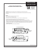
Verify input voltage and name plate voltage of heater for compatibility. Wiring can be done from either end of
heater. A inside or outside corner section is available for right angle mounting of two baseboard heaters and
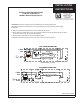
allowance should be made for locating wiring. See Figure 2 for knockout locations.
MOUNTING AND WIRING
1. Position the heater in the required location
preferably on an outside wall under a window.
2. Determine which end the power supply will enter
the heater. (This heater can be wired from either
end). Drill the appropriate hole into the wall or
floorfor the power supply, see Figure 2 for
knockout locations. Make sure that the electrical
power supply is disconnected at the circuit
breaker panel.
3. Remove the wiring compartment cover. If the
power supply is entering on the back of the
heater remove the knockout, install the cable
connector (not provided) and feed the wire
through the connector. Leave about 6 inches
of wire extending into the box for connection. If
the power supply enters on the bottom of the
heater, remove plug button from the bottom of
the wiring compartment, install the cable
connector (not provided) and feed the wire
through the connector. Push any excess cable
into the wall or floor.
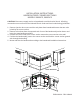
4. Remove the front cover of the baseboard. The
front cover is snapped on the element retainer
brackets. Position the heater on the wall and
determine the stud locations. Drill 3/16 inch
holes in the rear enclosure using the drill guide,
see Figure 2. Secure the heater to the wall with
minimum #8 screws 1 inch long. Snug the
heater up against he wall then back the screws
off about 1/2 inch to allow for expasion. If a
stud is not available use the appropriate fastener
such as toggle bolts or molly screw anchors
for hollow walls or screws and anchors for
masonry walls.
5. Replace the front cover by snapping it over the
element retaining brackets.
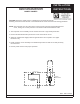
6. Remove the wire nut in the wiring compartment
and connect the power supply as shown in the
wiring diagrams, Figure 3. If you are using one
of the field installed accessories, refer to the
wiring diagram provided with the accessory.
7. Replace the wiring compartment cover and
restore power to the circuit. Turn the thermostat
up and wait 2-3 minutes to see if the heater is
operating properly. If the heater is not operating
disconnect the power at the circuit breaker box
and check wiring.
CLEANING INSTRUCTIONS
At the beginning of each heating season, it is
recommended that heaters be cleaned to eliminate
any accumulation of dust or lint. Before cleaning,
make sure the powers is OFF at the circuit breaker
panel and the heating element cool. Do not remove
front cover during cleaning. Use the narrow suction
attachment of the vacuum cleaner and move from
end to end and above and below fins and cabinet.
When cleaning is complete, turn power ON.
IN CASE OF PRODUCT FAILURE: It is the
obligation of the owner to furnish to the company
within the designated warranty period, the following
information:
1. Model number and date of manufacture of
product involved and date of purchase.
2. Complete description of the problem
encountered with product. Upon receipt of the
above, the company will reply to the owner within
a period not to exceed fifteen (15) working days,
the action to be taken by owner. When
requested, it shall be the obligation of the owner
to return the defective part to the company within
thirty (30) days after its removal, or otherwise to
follow instruction from the company. Return
parts to the appropriate service center.
2
8981 - REV.