
User Manual


INSTALLATION
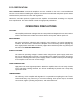
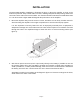
The PA1-1AEM amplifier installation is illustrated in figure 2. Mount the amplifier as close to the
antenna as practical. Keep coaxial cable runs short, avoiding sharp bends and pinching. Avoid loose
connectors at the ends of the coaxial cables. The antenna should be matched to an SWR better than
1.5:1 for best results. Higher SWR will degrade the performance of the amplifier.
1. Mount the amplifier away from the sources of heat, and where air can freely circulate around it.
Avoid mounting the amplifier in the engine compartment or near the exhaust pipe system.
It is also important to securely fasten the unit. An improperly mounted piece of equipment is
subjected to damage as it moves about and can cause serious injuries in an accident. Use bolts
through the holes in the amplifiers flange to fasten the unit to a secure mounting surface (see
figure 2).
Figure 2. Amplifier installation
Page 5
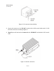
2. Wire the DC power connector (Cinch 4 pin female) directly to the battery if possible. Do not use
the present vehicle wiring. Use #10 AWG if possible and certainly no lighter than #12 AWG. To
avoid a possible fire, or other possible damage, make sure a fuse or circuit breaker is installed at
the battery end of the wire. Use the same size as the internal fuse listed in table I.
Attach DC input wires in accordance to the diagram in figure 3. If wires are too large for the holes,
solder them to the sides of the blades.