I I ~ e~~~~ I I USER MANUAL I MID-BAND I I I I I I I I CONTINUOUS DUTY POWER AMPLIFIERS 3370 SAN FERNANDO ROAD., #206 LOS ANGELES, CA 90065 TEL: I I I I VHF (323)256-3000 FAX: (323)254-3210 www.tplcom.
I ~l TABLE OF CONTENTS I I .GENERAL SPECIFICATIONS 2 OPERATING PRECAUTIONS 4 I INSTALLATION 4 I REMOTEMONITORING 5,1 OPERATOR ADJUSTMENTS 6 .WARRANTY 8 D I ,I ,- c I .
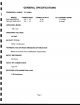
I -GENERAL SPECIFICATIONS [I FREQUENCYRANGE: 72-76 MHz I PA2-2AB-RSPS-P PA2-2AC-RXR-PS-P I OPERATINGMODE: MODEL .I POWER INPUT 0.5-1 0.5-1 W W POWEROUTPUT 10 W 60 W FM/CW OPERATINGVOLTAGE: I " c, ,.:1 110VAC EIA DUTYCYCLE: 100% I Continuous I HARMONICAND SPURIUSEMISSIONSATTENUATION:1 Meets or exceeds FCC Certification requirements.:1 IN/OUTIMPEDANCE: 50 Ohms. 1 1 IN/OUTRF CONNECTORS: Type "N" RECEIVERPATHINSERTIONLOSS:1 1 dBmaximum11 I ,I Page2.1 DC CURRENTDRAIN 1.5 Amps. 4 Amps.
I I General Specifications (continued) II I I OPERATINGTEMPERATURE: -200 to +500 Celsius. STORAGE TEMPERATURE: -400 to +850 Celsius. I OPERATINGHUMIDITY:':1 0% -85% RH (non-condensing). STORAGEHUMIDITY: I 0% -95% RH (non-condensing).
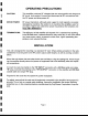
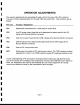
I -OPERATING J f PRECAUTIONS CAUTION: This l I DRIVE POWER: amplifier RF burns. the DC RF power Use an I TERMINATIONS: a ing: 50 of Ohm lower This unit I , is designed for must the unit ing the ers temperature.
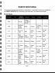
I -REMOTE MONITORING 11 The monitored functions are described in other sections. These same functions are available at the REMOTE MONITOR OB-9 connector on the rear panel. The outputs are as follows: I Monitor Signals I I GNO 1 Ground Chassis and Signal Ground VRM 2 Reflected Power Monitor Buffer Analog PTT 3 Input A t" c lVe Low 0 C Pen II t 0 ec or 'I I I I P h T us -0-Talk 8 V max, alarm on = 1 m A max 5.0 V 5 V max 0.5 mA max A t.
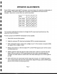
I I I OPERATORADJUSTMENTS I The operator adjustments are accessible through a slot in the cover of the RF enclosure. These are 10-turn potentiometers VR1 through VR5 and switch SW1. Their functions are as follows: I Ref. Des. FunctionI Adjustment I VR1 Determines the threshold for a valid input RF power level. VR2 Low RF power output threshold set to determine the alarm level for the LPA signal at the Remote Monitor connector.
I I ~ I OPERATORADJUSTMENTS Switch SW2, located inside the RF enclosure, is set according to the particular configuration of each amplifier. This switch is factory set at the time of manufacture and should not be changed.
I I WARRANTY rI TPL COMMUNICATIONS has tested and found this unit to function properly and to operate within the parameters of its stated specifications. I TPL COMMUNICATIONS warrants that this product is free from defects in material and workmanship. If found to be defective within two (2) years from the date of purchase, the factory at its discretion, will either repair or replace the unit at no cost provided the unit is delivered by the owner to the factory intact.