
User's Manual


I
-REMOTE MONITORING
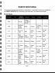
11 The monitored functions are described in other sections. These same functions are available at
the REMOTE MONITOR OB-9 connector on the rear panel. The outputs are as follows:
I Monitor Signals
I
I Chassis
GNO 1 Ground and Signal
Ground
'I Reflected 8 V max,
1 Am max
VRM 2 Power Buffer Analog alarm on =
I Monitor 5.0 V
P h T A t" 0.5 mA
us -0-- c lVe
I PTT 3 Talk Input Low 5 V max max
I Over 0 A t.20 mA
en c lVe
OTMP 4 Temperat-
CP
II t L 30 V max max
AI 0 ec or ow
ure arm
I 20 mA
VCC 5 +5 Volts Reference Supply +5 VOC max
I
.20mA
RFON 6 RF Input Open ActIVe 30 V max max
I On Collector Low
I Forward 5 V @
1 A" m max
VFM 7 Power Buffer Analog nominal
Monitor output
I Standing 20 mA".
Wave Open Active
SWR 8
R t. C II t L 30 V max max
I a 10 0 ec or ow
., Alarm
I Low 0 A t.20 mA
pen c lVe
LP A 9 Power
C II t L 30 V max max
Alarm 0 ec or ow
I Page 5
I