
User's Manual


I
I
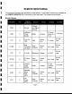
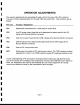
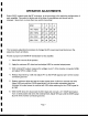
I OPERATOR ADJUSTMENTS
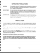
The operator adjustments are accessible through a slot in the cover of the RF enclosure.
I These are 10-turn potentiometers VR1 through VR5 and switch SW1. Their functions are as
follows:
I Ref. Des. Function I Adjustment
I VR1 Determines the threshold for a valid input RF power level.
VR2 Low RF power output threshold set to determine the alarm level for the LPA
I signal at the Remote Monitor connector.
VR3 Sets the Forward Power Monitor (VFM) voltage at the Remote Monitor connector.
I VR4 SWR threshold set to determine the alarm level for the SWR signal at the
Remote Monitor connector.
I VR5 Sets the RF output power level.
I SW1 Determines the method of RF output power control. The TEST position provides
regulated DC control. The OPER position provides RF feedback leveling control.
I A basic understanding of RF principals is necessary before making any adjustments to the
I unit. This includes the knowledge of the relationship of forward and reflected power relative to
SWR, etc. Adjustment also requires the familiarity and use of test equipment. If in doubt,
consult your distributor, dealer or the manufacturer about changes.
I
I
I
I
'I
"
1 Page 6
I