
User's Manual


I
I OPERATOR ADJUSTMENTS
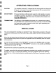
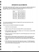
~ Switch SW2, located inside the RF enclosure, is set according to the particular configuration of
each amplifier. This switch is factory set at the time of manufacture and should not be
I changed. Never turn on more than one switch at any time!
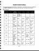
I SW2 -1 -2 -3 -4
14V / REM on off off off
I 28V / REM off on off off
14V/PSC off off on off
r I 28V / PSG off off off on
I
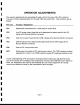
I The necessary adjustment procedure to change the RF power level must be done in the
sequence shown as follows:
,I Provide a proper low-VSWR RF termination for the amplifier.
1. Place SW1 into the RUN position.
I 2. Apply the minimum RF drive level and adjust VR5 for nominal output power.
I 3. With nominal RF output, measure the voltage on pin 7 of the monitor connector (VFM)
and adjust VR3 to obtain 5 volts
I 4. Reduce input drive by 3 dB and adjust VR1 so the RFON signal at pin 6 of the monitor
connector goes low
I 5. Restore minimum drive and set the output power down 3 dB from nominal with VR5.
Adjust VR2 just until the LPWR signal at pin 9 of the monitor connector goes low.
I Increase the output power to nominal with VR5 while watching for the LPWR signal to
go high.
I 6. With the RF drive off, disconnect the 50 U load and connect a 3:1 VSWR termination.
Turn on drive power and set to the nominal level. Adjust VR4 just until the SWR signal
at pin 8 of the monitor connector goes low.
I
I Page 7
I
,--