
User Manual


INSTALLATION
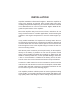
Amplifier installation is illustrated in Figure 1. Mount the amplifier as
close to the antenna as practical. Keep coaxial cable runs short,
avoiding sharp bends and pinching. The antenna should be matched
to an SWR better than 1.5:1 for best results. Higher SWR will de-
grade the performance of the amplifier.
Mount the amplifier away from sources of heat, and where air can
freely circulate around it. In mobile applications, avoid mounting the
amplifier in the engine compartment or near the exhaust pipe sys-
tem.
In any mobile installation it is important to securely fasten the unit.
An improperly mounted piece of equipment is subject to damage as
it moves about and can cause serious injuries in an accident. Use
bolts through the holes in the amplifier flange to fasten the unit to a
secure mounting surface.
Wire the DC power connector (Cinch 4 pin female), for the amplifier,
directly to the battery if possible. Do not use the present vehicle
wiring. Use #12 AWG if possible and certainly no lighter than #14
AWG. To avoid a possible fire, or other possible damage, make sure
a fuse or circuit breaker is installed at the battery end of the wire.
Use the same size as the internal fuse listed in the specifications.
Connect the radio transceiver to the “RF INPUT” terminal and the
antenna to the “RF OUTPUT” terminal on the amplifier, with 50 Ohm
coaxial cable and UHF connectors. Terminating information for the
DC connector is given on the following pages.
This amplifier produces sufficient power to cause significant heating
of low quality, or incorrectly selected coaxial cable and fittings. Use
high quality cables and fittings to reduce heating and power losses.
Page 4