
User's Manual


Metering and Indicators
(Continued)
LOPWR . . . . . . . . . . . . . . . . . . . . . . Flashing red alarm LED when RF output power is below an
internally preset level.
FANS . . . . . . . . . . . . . . . . . . . . . . . . Flashing red alarm LED when a fan failure occurs.
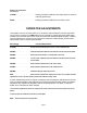
OPERATOR ADJUSTMENTS
The operator can turn the main power on or off with the switch located in the lower right hand
corner of the front panel. The HMS status can be checked by toggling the meter select switch
located in the lower left hand corner of the front panel and viewing the status display. A display
contrast adjustment is provided on the front panel, between the status display and the meter
select switch. This is a ten turn potentiometer.
Ref. Design Function/Adjustment
P1 (VR1) . . . . . . . . . . . . . . . . . . . . . RF output power level adjustment. This is a 10-turn potentiometer.
P3(VR3) . . . . . . . . . . . . . . . . . . . . . VSWR threshold set to determine the alarm level for the front panel indicator.
P4(VR4) . . . . . . . . . . . . . . . . . . . . . Determines the threshold for a valid input RF power level.
P5(VR5) . . . . . . . . . . . . . . . . . . . . . Low RF power output thresh old set to determine the alarm level for the front
panel indicator.
P6(VR6) . . . . . . . . . . . . . . . . . . . . . Meter calibration potentiometer for RF power output.
P7(VR7) . . . . . . . . . . . . . . . . . . . . . Meter calibration potentiometer for RF reflected power.
P8(VR8) . . . . . . . . . . . . . . . . . . . . . Calibration setting for relative input power.
SW1 . . . . . . . . . . . . . . . . . . . . . . Determines the method of RF output power control. The up position provides
regulated DC control. The down position provides RF feedback leveling control.
A basic understanding of RF principles is necessary before making any adjustments to the unit.
This includes knowledge of the relationship of forward and reflected power relative to SWR etc.
Adjustment also requires the familiarity and use of test equipment. If in doubt, consult your
dealer or the manufacturer about changes.
The necessary adjustment procedure to change the RF power level must be done in the sequence shown as
follows:
Provide a proper low VSWR RF termination for the amplifier.
SW1 Set this switch to the up (test) position.
Page 6