
Installation Guide

Revised 6/11/18 Copyright © 2018 Trade-Wind Manufacturing, LLC Proverbs 22:29 Page 10
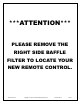
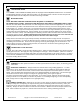
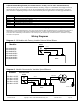
3-Speed Switch Wiring Details (for remote blowers, usually “roof or wall” mounted blowers)
When connecting the liner to a 3-speed remote blower, the wiring ―rough-in‖ to the blower must include 5 wires (4
conductor wires and 1 ground wire). This can be accomplished by using either two 2-strand Romex
®
type wires
(one must have a separate ground) or one 4-strand conductor plus one ground wire. The wire gage should be 14.
Black
120 volt AC from electrical panel (usually black) to liner
White
Neutral from electrical panel (white) to liner.
Green
Ground from electrical panel (usually green) to liner
Wire 1*
High Speed from liner to blower
Wire 2*
Medium Speed from liner to blower
Wire 3*
Low Speed from liner to blower
Wire 4*
Neutral from liner to blower (usually green)
Wire 5*
Ground from liner to blower
* Consult the switch manufacturer's installation instructions and wiring diagram when substituting control switches.
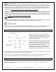
IMPORTANT: Trade-Wind Manufacturing, LLC does not pay warranty claims for damage to liners or components connected to
other brand blowers inconsistent with these Installation Instructions. Always consult the switch manufacturer's installation
instructions when substituting control switches. The warranty may be voided if any unauthorized service, alterations or repairs
are made to the product.
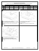
Wiring Diagrams
Diagram 1: All Models with Factory Installed Internal Motor/Blower
Models:
VSL436622RC
VSL442622RC
VSL448622RC
VSL4421222RC
VSL4481222RC
VSL4541222RC
VSL4601222RC
Diagram 2: Models Connected to Variable Speed Blowers
Models:
VSL436-0-22-BF
VSL442-0-22-BF
VSL448-0-22-BF
VSL454-0-22-BF
VSL460-0-22-BF
House Electrical
Panel
Green
120V Black
White
(N)
Liner
Liner
Ventilator
House Electrical
Panel
Green
White (N)
120V Black
(L)
120V Red
Green, Ground