
Installation Guide


Revised 6/11/18 Copyright © 2018 Trade-Wind Manufacturing, LLC Proverbs 22:29 Page 14
In-line Damper (for ventilation systems utilizing a roof cap or wall cap without a built-in damper)
In cold weather areas, installing an “in-line” damper may be the preferred type of installation. This is because
in-line dampers installed just above the perimeter of the heated space (the ceiling) will reduce the amount of
cold air traveling down the duct into the heated space and into the kitchen through the ventilator.
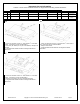
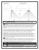
In-line dampers must be installed so that the exhaust air flow will open the butterfly blades.
For horizontal duct runs, the in-line damper must be installed so that the hinge between the two butterfly
blades is vertical—the hinge pin must point up and down. Otherwise, because of gravity, the damper’s blades
will not close and the damper will not prevent backdrafts.
For vertical duct runs, the in-line damper’s hinge will be horizontal (sideways), which is correct for vertical
duct runs. Gravity will help close the damper blades after each use.
For upward slanted duct runs, the in-line damper’s hinge must point to the top and bottom sides of the duct.
In his position, gravity will help close the damper blades after each use. Otherwise, because of gravity, the
damper’s blades will not close and the damper will not prevent backdrafts.
5. Roof Caps and Wall Caps
The roof cap or wall cap is the termination point of the venting system that allows the exhaust air to exit to
the outdoors. All sections of this fitting must have an equal or greater air path area than the ventilator’s
discharge port. If any section of the roof cap or wall cap is smaller than the ventilator’s discharge port, the
entire ventilation system will lose efficiency and the restriction will cause increased static pressure.
IMPORTANT: Even though the intake side of the roof cap or wall cap may be properly sized, roof caps or wall
caps with built-in dampers must be made so that when the damper is fully open, the actual open area of the
final air path is equal to or greater than the discharge port of the ventilator. Any undersized portion of a roof
cap or wall cap will cause excessive static pressure that may result in rattling, vibration and air buffeting
noises, as well as inadequate ventilation.
6. Attaching Duct to House Framework
The ventilation system should be attached to the framework in such a manner that the weight of the duct and
fittings is supported with no stress on the duct joints, fittings or on the ventilator. All ducting should be
attached so as to avoid any possible duct vibration from being transferred to the house’s framework.
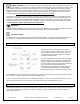
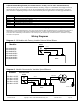
7. Duct Sizing Chart and Area Calculations
Ventilator Discharge Port
Types & Sizes
Duct Type Required
Duct Size
(in Square Inches)
Minimum Discharge Size
of Roofcap or Wallcap
Outside Opening
6” Diameter, Round
28.3”
6” Round Metal Duct
28.5”
28.3”
7” Diameter, Round
38.5”
7” Round Metal Duct
38.5”
38.5”
8” Diameter, Round
50.25”
8” Round Metal Duct
50.25”
50.25”
10” Diameter, Round
78.5”
10” Round Metal Duct
78.5”
78.5”
3.25” x 10” Rectangular
32.5”
3.25” x 10” Rectangular Metal Duct
32.5”
32.5”
Calculating Square Inches of Various Duct Sizes & Types
ROUND DUCT
RECTANGULAR DUCT or WALL/ROOF CAP
Radius
x
Radius
x
3.1416
=
Area (Sq. Inches)
Width
x
Depth
=
Area (Sq. Inches)
x
x
=
x
=
The “radius” is one-half the diameter of a round duct,
e.g., ½ of a 10” round duct is 5”. 3.1416 is “Pi”, the
“constant” used when calculating the area of a circle.