
Installation Guide

Revised 6/11/18 Copyright © 2018 Trade-Wind Manufacturing, LLC Proverbs 22:29 Page 9
PART 4 Electrical Connection
IMPORTANT: Copy this page and the next 2 pages to your electrical installer.
WARNING! Ensure that the power supply is disconnected before proceeding. Verify that the power supply
matches the ratings found on the appliance data label before proceeding. The complete appliance must be
properly grounded at all times when electrical power is applied. Do not ground the appliance with the neutral
(white) house supply wire. A separate ground wire must be utilized. Failure to complete electrical connections
properly may result in damaged or non-functional systems. Follow instructions carefully to ensure proper
installation.
It is the owner’s responsibility to ensure that a qualified person performs the electrical connection of this appliance.
The electrical installation, including minimum supply wire size, must comply with the National Electric Code
ANSI/NFPA 70-1990 (or latest revision) and local codes and ordinances. A copy of this standard may be obtained
from: National Fire Protection Association, 1 Batterymarch Park, Quincy, Massachusetts 02269-9101
INSTRUCTIONS: A 15 to 20 amp electrical service is recommended for proper electrical supply. Before
determining, calculate amp ratings based on the product label found on the liner and the ventilator. Always observe
local building codes. Always use a dedicated circuit. Line load is calculated by adding the amperage of the
halogen lights to the rated amperage of the ventilator (either in-line or roof top). If the ventilator is rated in watts
rather than amps, divide the watts by 120 and this will give you the amperage rating. The Trade-Wind
®
liner,
without the internal motor, is supplied with a 6.0 amp variable speed fan control. Make sure the rated amperage on
the ventilator does not exceed 6.0 amps.
CAUTION: The neutral wire (usually white) for the blower/motor must connect to the same neutral wire
that comes from the electrical panel to the liner. It is recommended to run a white neutral wire from the liner’s white
neutral wire along the same path as the red wire from the liner’s variable speed control to the blower/motor.
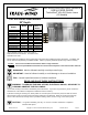
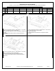
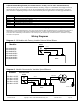
Variable-Speed Control Wiring Details (for remote blowers, usually “in-line” blowers)
Black
120 volt AC from electrical panel (usually black) to liner
White
Neutral from electrical panel (white) to liner
Green
Ground from electrical panel (usually green) to liner
Red
120 volt AC variable control from liner to 120 volt AC of variable speed ventilator
CAUTION: Do NOT connect this wire to a 3-speed blower.