
User's Guide

6
Radio 148221 User Guide
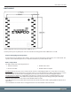
Transmit Mode
All packets sent over the air are either Addressed or Broadcast packets. Broadcast and Addressed delivery can be
controlled dynamically with the API Control byte. Contact the factory for details.
When a radio has data to transmit, it sends it out on its reserved timeslot. The number of devices on a network is
configurable at the factory.
To increase the odds of successful delivery the host application is required to Transmit Retries.
RF Serial Communication is not transparent to the OEM host and the Manufacturer will need to advise the Host on
how to apply data packaging for transmission OTA (over the air). Contact the factory for details.
Receive Mode
Serial data can be asynchronously received by Radio 148221 OTA then directed to the Host serial port.
RSSI - Received Signal Strength
RSSI is in units of dBm and is available through serial communication. Contact the factory for details on reading this
information from the transceiver.
System Timing and Latency
Latency is the amount of time that it takes for an action to take place. There are different actions available in TapNet
including remote digital control and serial data transmission/reception.
IO latency is dependent on the size of the RF network.
7 Device networks require a maximum of 62.5ms for one transceiver to transmit information to the system and in as
little as 9ms to transmit information directly.
16 Device networks require a maximum of 143ms for one transceiver to transmit information to the system and in as
little as 9ms to transmit information directly.
System Throughput
Maximum System Throughput
Timekeeper to Listener = 1280 baud continuous max
host throughput rate
Listener to Listener in direct mode = 1280 baud
continuous max rate
Listener to Listener in sync mode = 640 bytes baud
continuous
Maximum host serial payload size is 64 bytes.
RF Data Rate default is 123kBaud.
Other data rates and payload sizes are available. Contact TAPCO for details on custom serial data configurations.
System Operation
The Radio 148221 network is preconfigured at the factory so all the user needs to do is power up the devices and
they will automatically sync and begin working. IO and OTA serial functionality is only available once a device is
sync’d.
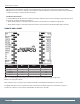
A flashing green LED indicates the TimeKeeper device. The Green LED specifically indicates that data has been
transmitted OTA.
A red flashing LED indicates that a Listener Device is in sync with the TimeKeeper. The Red LED specifically indicates
that RF data has been received OTA.