
Manual


9
TM102N
Revised
2.4.14
way out. Doing this will ensure the ball joint
is out as far out as possible. Torque the cam
bolt hardware to 95 ft./lbs.
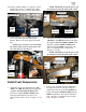
11. Install the OE nuts onto the OE strut upper
studs. Using a suitable cutting tool, (abrasive
cutoff wheel, Sawz-all, etc.), carefully cut off
the top nipple part of the studs. Once the
studs have been cut, remove the OE nuts.
NOTE: Take care to not cut into the
threads of the studs.
12. Attach the strut spacer (82-8272) to the top of
the strut using the OE hardware. Be sure to
use thread locker and torque to manufacturers
specifications.
13. Remove the OE lower strut mounting clips
from the strut.
14. Fit the OE strut into the stock mounting loca-
tions. Fasten using the supplied (3 per side)
7/16” hardware on the top from hardware
pack (90-6317). Torque to 35 ft./lbs.
NOTE: Be sure that the locating tab on
the top ring of the strut spacer is facing to-
ward the outside of the vehicle.
IMPORTANT!: Be sure the OE wiring
harness clips are reinstalled to the strut spacer
studs. Failure to do so may result in the wiring
harnesses being damaged by the steering col-
umn.
15. Secure the OE lower strut cross pin to the
Nipple Area To
Be Trimmed
Cutting Tool OE Strut Upper
Mounting Studs
82-8272
Strut
Spacer
OE Strut
OE Nuts
7/16”
Nuts and
Washers
Strut
Assembly
82-8274 Drvr and 82-8277
Pass Upper Control Arm