High Efficiency Horizontal and Vertical Water-Source Comfort System AxiomTM 1/2 - 20 Tons - 50 Hz - Vertical (Model GEV) 1/2 - 12-1/2 Tons - 50 Hz - Horizontal (Model GEH) WSHP-PRC003-EN
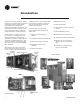
R Introduction Imagine a full range of comfort utilizing efficiency, sound attenuation, integrated controls and superior maintenance accessibility... Trane imagined it, designed it and built it. The AxiomTM line of vertical and horizontal water source heat pumps help create an advanced comfort system for comfort solutions. The entire range of Axiom units - 1/2ton to 20 tons - is designed with the highest standards in mind: Ease of maintenance; Indoor air quality; Quieter operation and higher efficiencies.
R Contents Introduction 2 Model Number Descriptiom 4 General Data 5 Features and Benefits Options 10 Controls 17 Application Considerations 25 Performance Data 29 Electrical Performance 29 Cool and Heat Performance - English 30 Correction Factors - English 72 Cool and Heat Performance - Metric 75 Correction Factors - Metric 117 Fan Performance - English/Metric 120 Sound Data 134 Control Wiring 135 Dimensional Data 143 Accessories 171 Thermostats and Zone Sensors 180 Opt
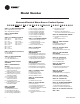
R Model Number Horizontal/Vertical Water-Source Confort System G E H B 036 9 1 D 0 1 1 0 D L D 0 1 0 N 0 0 1 1 0 0 0 1 0 0 0 0 0 0 0 5 10 DIGITS 1-3: UNIT CONFIGURATION GEH = High Efficiency Horizontal GEV = High Efficiency Vertical DIGIT 4: DEVELOPMENT SEQUENCE B DIGITS 5-7: NOMINAL CAPACITY 006 = 1/2 Ton 072 = 6 Ton 009 = 3/4 Ton 090 = 7-1/2 Ton 012 = 1 Ton 120 = 10 Ton 015 = 1 1/4 Ton 150 = 12-1/2 Ton 018 = 1 1/2 Ton 180 = 15 Ton 024 = 2 Ton 240 = 20 Ton 030 = 2 1/2 Ton 036 = 3 Ton 042 = 3 1/2 Ton DI
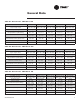
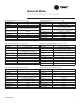
R General Data Table G1: General Data - GEH 006 to 018 Model GEH 006 009 012 015 018 Unit Size (in/mm) 40 x 15 x 20 1016 x 381 x 508 40 x 15 x 20 1016 x 381 x 508 40 x 15 x 20 1016 x 381 x 508 46 x 17 x 23 1168 x 432 x 584 46 x 17 x 23 1168 x 432 x 584 Length x Height x Depth Compressor Type Rotary Rotary Rotary Rotary Reciprocating Approx. weight with pallet/without pallet (lbs/kg) 188 / 158 85.3 / 71.7 188 / 158 85.3 / 71.7 188 / 158 85.3 / 71.7 188 / 158 85.3 / 71.
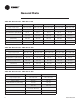
R General Data Table G4: General Data - GEV 006 to 018 006 Model GEV Unit Size (in/mm) Length x Height x Depth 009 012 015 018 21-1/2x31-1/4x19-1/5 21-1/2x31-1/4x19-1/5 21-1/2x31-1/4x19-1/5 21-1/2x31-1/4x19-1/5 21-1/2x38-1/4x21-1/2 546 x 793 x 495 546 x 793 x 495 546 x 793 x 495 546 x 793 x 495 546 x 997 x 546 Compressor Type Rotary Rotary Rotary Rotary Reciprocating Approx.
R General Data Table G7: General Data - GEV 072 to 180 Model GEV 072 090 120 150 180 Unit Size (in/mm) Length x Height x Depth 42 x 62-5/8 x 36-1/4 1067 x 1591 x 921 42 x 62-5/8 x 36-1/4 1067 x 1591 x 921 Compressor Type Reciprocating (2) Reciprocating (2) Scroll (2) Scroll (2) Scroll (2) Approx.
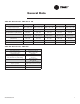
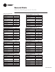
R General Data Air-to-Refrigerant Coils Table G9: GEH/GEV 006 Working Pressure Tubes High Tubes Deep No. of Circuits Finned vol. (in/mm) (H x W x D) Coil Surface Area (Ft2) Fins Per Inch Tube Material Tube OD (in/mm) Wall Thickness Return Bends Table G13: GEV 015, 018, 024, 030 425 14 2 1 14 x 16 x 1.734 356 x 406 x 44 1.56 12 Copper 3/8 / 10 0.014 Copper Table G10: GEH/GEV 009 Working Pressure Tubes High Tubes Deep No. of Circuits Finned vol.
R General Data Air-to-Refrigerant Coils Table G17: GEH/GEV 060 (2-compr. circuit) Table G20: GEH/GEV 120 (2-compr. circuit) Working Pressure Tubes High Tubes Deep No. of Circuits Finned vol. (in/mm) (h,w,d) Working Pressure Tubes High Tubes Deep Coil Surface Area (Ft2) Fins Per Inch Tube Material Tube OD (in/mm) Wall Thickness Return Bends 425 18 (GEH)/ 24 (GEV) 4 6 refrig flow paths (2X) 18 x 48 x 3.464 / 457 x 1219 x 88 (GEH) 24 x 34 x 3.464 / 609 x 864 x 88 (GEV) 6.00 (GEH) 5.
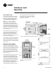
R Features and Benefits Design Advantages The horizontal and vertical configuratios range in capacities from 1/2 to 5 tons. The innovative designs offers superior field flexibility at the jobsite along with service accessibility. ment may be field converted through a service kit to aid in stocking of a single unit variation. See Figure 2 for component platform location.
R Features and Benefits GEH/GEV 6 to 20-Ton Cabinet The GEV model is also capable of onsite modifications. With the vertical configuration, the supply-air is easily converted from a top supply-air to a back supply-air with a service retrofit kit. The return-air option is order specific. There are four combinations. See Figure 5 for the four GEV supply/reutm air options. The cabinet design incorporates sturdy (non painted) galvanized metal form maximum durability and corrosive resistive exterior.
R Features and Benefits Hanging Device: 1/2 to 5-ton Drain Pan The hanging bracket resides in the chamfered corner of the horizontal 1/2 to 5 ton equipment. This partially-concealed bracket design eliminates added height, width, or length to the product. The brackets are factory mounted to shorten job installation requirements. The unit drain pan is composed of plastic, corrosive resistive material. The pan is positively sloped to comply with ASHRAE 62 for (IAQ) indoor air quality conformity.
R Features and Benefits Schrader Connections: 1/2 to 5-ton The connections for the low and high side of the refrigeration system are located directly beside the control box at the front, service access panel. See Figure 11 for schrader connection lotion. Co-axial Water-to-Refrigerant Coil Figure 11: Schrader connections Figure 12: Water connections - small ton The unit’s internal heat exchanging water coil is engineered for maximum heat transfer.
R Features and Benefits Blower Motor: 1/2 to 5 ton The supply-air (blower) motor is a multi-speed motor with internal thermal overload protection. The motor bearings are permanently lubricated and sealed. Access to the 6 through 25 ton units is made through the back of unit by way of two panels, and/or through a side access panel if adjustment to the motor belt or motor base are needed. Blower Housing All motors are factory wired to the option selected.
R Features and Benefits Boilerless Control/Electric Heat (option) The boilerless electric heat option is composed of a nichrome open wire design. This single stage of electric heat is used as a primary heating package to lock out compressor operation in the event that entering-water temperatures reach below 58 F (14.4 C). On a call for heating, the electric heater is activated, locking out the compressor. Once the entering water temperature rises, above 58 F (14.
R Features and Benefits Hot Gas Reheat (option) Proper Hot Gas Design For space conditioning and climate control, Trane provides an accurate and cost effective dehumidification control through a hot gas reheat option. This option is designed to accommodate unit sizes 012, 036, 060 and 072 through 240. The factory installed hot gas reheat option is only available with Deluxe or ZN524 controls packages.
R Features and Benefits Controls Controls by Trane Whether involved in a retrofit or new construction application, Trane has the control design to fit your system requirement. Our control options provide a broad range of packages from the most cost efficient 24 volt standalone to a complete building automation solution, Trane is the right choice in comfort gratification. The following chart provides a brief overview in the different control combinations.
R Features and Benefits Basic Controls Basic 24 Volt Controls The basic 24 V electromechanical unit control provides component protection devices for maximum system reliability. Each device is factory mounted, wired and tested. See Figure 20 for the unit control box. excessive discharge pressures that exceed 395 psig.
R Features and Benefits Deluxe Controls Deluxe 24V Electronic Controls The deluxe 24V electronic unit control provides component protection devices similar to the basic design, but contains upgraded features to maximize system performance to extend the system life. Each device, is factory mounted, wired, and tested in the unit. See Figure 23 for unit control box.
R Features and Benefits Deluxe Controls Microprocessor Design The 24 volt deluxe design is a microprocessor-based control board conveniently located in the control box. The board is unique to Trane water-source products and is designed to control the unit as well as provide outputs for unit status and fault detection. The Trane microprocessor board is factory wired to a terminal strip to provide all necessary terminals for field connections. See Figure 27 for the deluxe 24V control board.
R Features and Benefits ZN510 & ZN524 Controls Tracer ZN510 & ZN524 Controls The Tracer ZN510 and ZN524 are direct digital control (DDC) systems specifically designed for single and dual circuited water-source equipment to provide control of the entire unit, as well as outputs for unit status and fault detection. Each device is factory installed, commissioned, and tested to ensure the highest level of quality in unit design.
R Features and Benefits ZN510 & ZN524 Controls Direct Digital Controls When the ZN510 or ZN524 controller is linked directly to the Tracer Summit, each Tracer Summit building automation system can connect a maximum of 120 Tracer ZN510 or ZN524 controllers. See Figure 27 for the Tracer ZN524 board. Figure 27: Tracer ZN524 board. Tracer ZN510 and ZN524 functions include: Compressor Operation The compressor is cycled on and off to meet heating or cooling zone demands.
R Features and Benefits ZN510 & ZN524 Controls More ZN524 Controller Functions: When the building owners choice is Trane Tracer controls, the ZN524 controller is required when any of the following applications are selected on a single and dual circuited equipment.
R Features and Benefits ZN510 & ZN524 Controls Building Control Advantages The Tracer ZN510/ZN524 controller has the ability to share information with one or several units on the same communication link. This sharing of information is made possibe via a twisted pair of wire and a building automation system or through Trane’s RoverTM service tool . An advantage of installing a ZN510/ZN524 is its capability to work with other LonTalk certified controllers.
R Application Considerations Figure 29: Horizontal unit installation 4” 1/ e: op l S .5 (6 ) m m 12”/ 305mm Slope: 1/4” (6.5 mm) Hanging the Horizontal The horizontal unit GEH A is a ceiling hung unit. It is usually applied as a totally concealed unit above an acoustical ceiling grid. Because the GEH A is equipped with several inlet and discharge arrangements, it allows for numerous application needs. When hanging the horizontal design, the unit should be pitched approximately 1/4-inch (6.
R Application Considerations Condensate Traps When designing a condensate trap for the water-source system, it’s important to consider the unit’s draw through design. Under normal conditions, condensate runs down the coil fins and drips into a condensate pan. In situations where no trap is installed, the water level that would be maintained in the trap to create a seal, backflows through the drainline into the unit.
R Application Considerations Distributed Pumping System A distributed pumping system contains either a single or dual pump module, specifically sized for each water-source heat pump, then connected directly to the units supply and return lines. The distributed system’s supply and return lines should be sized to handle the required flow with a minimum pressure drop. 1. Hose kits are used to connect the water supply and return line to the water inlets and outlets.
R Application Considerations Installation Made Easy Installing a horizontal unit inside a corridor to enhance sound attenuation provides value to duct design. Trane takes this fact one step further. The new GEH design offers same side return-air/supply-air access to the unit. This access is contained within the overall dimension of the units length as shown in Figure 32.